Language selection

Search

Patent 2154894 Summary

Third-party information liability

Some of the information on this Web page has been provided by external sources. The Government of Canada is not responsible for the accuracy, reliability or currency of the information supplied by external sources. Users wishing to rely upon this information should consult directly with the source of the information. Content provided by external sources is not subject to official languages, privacy and accessibility requirements.

Claims and Abstract availability

Any discrepancies in the text and image of the Claims and Abstract are due to differing posting times. Text of the Claims and Abstract are posted:

  • At the time the application is open to public inspection;
  • At the time of issue of the patent (grant).
(12) Patent: (11) CA 2154894
(54) English Title: CONTAINER HAVING NO-GLUG POURING SPOUT
(54) French Title: RECIPIENT AYANT UN BEC VERSEUR EVITANT LES GLOUGLOUS
Status: Deemed expired
Bibliographic Data
(51) International Patent Classification (IPC):
  • B65D 47/32 (2006.01)
  • B65D 1/20 (2006.01)
(72) Inventors :
  • RING, CARL D. (United States of America)
(73) Owners :
  • RING CAN CORPORATION (United States of America)
(71) Applicants :
  • RING CAN CORPORATION (United States of America)
(74) Agent: NORTON ROSE FULBRIGHT CANADA LLP/S.E.N.C.R.L., S.R.L.
(74) Associate agent:
(45) Issued: 2001-12-04
(86) PCT Filing Date: 1994-04-11
(87) Open to Public Inspection: 1995-06-08
Examination requested: 1997-06-26
Availability of licence: N/A
(25) Language of filing: English

Patent Cooperation Treaty (PCT): Yes
(86) PCT Filing Number: PCT/US1994/003908
(87) International Publication Number: WO1995/015104
(85) National Entry: 1995-07-27

(30) Application Priority Data:
Application No. Country/Territory Date
08/159,564 United States of America 1993-12-01

Abstracts

English Abstract


A blow molded plastic container (10) having a small diameter vent tube (30)
integrally molded on the top wall and forming an air vent passageway between
the pour spout opening (28) and the chamber (22) in the bottle. A
substantially larger hollow handle (46), closed at both ends, is integrally
molded on top of the vent tube in spaced relationship above the top wall (24)
to form a hand opening.


French Abstract

Un récipient plastique (10) réalisé par extrusion-soufflage a un tube d'aération moulé (30) de petit diamètre, tenu d'une pièce avec la paroi supérieure du récipient, pour permettre un passage de l'air entre le bec verseur (28) et la chambre (22) du récipient. Une poignée creuse (46) sensiblement plus large, fermée aux deux extrémités, est tenue d'une pièce avec le tube d'aération en état espacée de la paroi supérieure (24) pour former une ouverture pour la main.

Claims

Note: Claims are shown in the official language in which they were submitted.


9
CLAIMS
1. A blow molded plastic container comprising a bottom (12), side
wall means (14, 16, 18, 20) extending upwardly from said bottom and
defining therewith a chamber (22) for containing a fluid, top wall means
(24) closing said chamber and having a spout (26) forming an opening (28)
through which the fluid may be poured from said chamber, a hollow vent
tube (30) formed integrally on said top wall means (24) and having a front
open end (32, 34) communicating with said spout opening (28) and a rear
open end (42) communicating with said chamber (22), a hollow handle
(46) closed at its front and rear ends (48, 50), and means (52, 54)
integrally connecting the front and rear ends of said handle on said vent
tube.
2. The plastic container of claim 1, the front end (32, 34) of said
vent tube opening upwardly into said spout.
3. The plastic container of claim 2, comprising deflector means (44)
extending across a rear portion of said spout opening (28) adjacent the
front end (32, 34) of said vent tube.


-10-

4. The plastic container of claim 1, said
connecting means including first and second web strips
(52, 54) connecting the front and rear ends (48, 50) of
said handle on said vent tube (30) and mounting said
handle in spaced relation from said top wall means (24)
to form a hand opening (56).
5. A blow molded plastic container comprising a
bottom, side wall means extending upwardly from said
bottom and defining therewith a chamber for containing
a fluid, top wall means closing said chamber and having
a spout forming an opening through which the fluid may
be poured from said chamber, a hollow vent tube formed
integrally on said top wall means and having a front
open end communicating with said spout opening and a
rear open end communicating with said chamber, a hollow
handle closed at its front and rear ends and overlying
said vent tube.
6. The plastic container of claim 5, the front
end of said vent tube opening upwardly into said spout.
7. The plastic container of claim 6, comprising
deflector means extending across a rear portion of said
spout opening adjacent the front end of said vent tube.
8. The plastic container of claim 5, connecting
means including first and second web strips connecting
the front and rear ends of said handle over said vent
tube and mounting said handle in spaced relation from
said top wall means to form a hand opening.

Description

Note: Descriptions are shown in the official language in which they were submitted.


WO 95/15104
PCT/US94/03908
CONTAINER HAVING NO-GLUG POURING SPOUT
TECHNICAL FIELD
This invention relates generally to containers for dispensing liquid
and more specifically to a container having a novel pouring spout
arrangement by which the space above the liquid is vented to permit air
to be drawn into the space during a pouring operation to prevent the
glugging or gulping phenomenon associated with many conventional
bottles.
This invention is particularly applicable to larger blow-molded plastic
jugs or bottles used for dispensing a variety of different types of liquids,
some of which may be toxic or flammable. As the bottle is tipped
forwardly, the mouth or neck portion will normally be lowered below the
liquid level in the bottle, trapping the air in the bottle above the liquid.
If no vent is provided to admit air into this region, the flow of liquid out
of the bottle will alternate with the flow of air into the jug, causing a
glugging or gulping action. Because of the glugging action the poured
stream is difficult to control, so that the user may make a mess with the


WO 95/15104 PCTIUS94/03908
_.
2
liquid. When that liquid is toxic or flammable this can create a dangerous
situation.
:BACKGROUND ART
In the past, various attempts have been made to provide large blow
molded plastic containers in which the hollow handle forms a vent
passageway between the spout and chamber in the bottle to overcome this
glugging problem. Typical prior proposals are illustrated in U.S. Patents
3,251,514, 4,412,633, 4,804,119, and in PCT International Publication No.
WO-86/02334, and those designs are improvements over the conventional
bottles. Another particularly effective novel design is illustrated in
applicant's copending Application Serial No. 08/090,760.
In such bottles the hollow handle is sufficiently large in size so as to
be comfortable and secure to grasp. Consequently, during the pouring
operation some liquid may inadvertently flow back through the air
passageway formed in the hollow handle and will collect within the handle
if it doesn't all drain back into the chamber and the bottle. If the liquid


WO 95/15104 ~ PGT/US94/03908
3
is a hazardous waste material the liquid collected in the large sized hollow
handle could be substantial in volume and this creates an undesirable
handling and disposal problem of the bottle. The need exists for a
solution to this problem.
DISCLOSURE OF THE INVENTION
Accordingly a primary object of this invention resides in the
provision of a blow molded plastic bottle having a small diameter no-glug
air vent tube forming an air passageway between the pouring opening and
the spout and the liquid containing chamber in the bottle and a hollow
handle closed at both ends.
Still another object of the invention resides in the provision of the
above blow molded plastic bottle in which the vent tube is of small
diameter and is integrally molded onto the outside of the top wall of the
bottle, and the larger hollow handle is integrally mounted on top of the
vent tube.


~ W ~.~~ 9~
- 4 -
A further object of the invention resides in
the provision of the above blow molded plastic bottle
in which the hollow handle is integrally molded at its
opposite closed ends by thin web sections to the front
and rear ends of the vent tube.
.Another object of the invention resides in
the provision of the above plastic bottle which can be
readily manufactured by a blow molding process.
A construction in accordance with the
present invention comprises a blow molded plastic
container comprising a bottom, side wall means
extending upwardly from the bottom and defining
therewith a chamber for containing a fluid, top wall
means closing the chamber and having a spout forming an
opening through which the fluid may be poured from the
chamber, a hollow vent tube formed integrally on the
top wall means and having a front open end
communicating with the spout opening and a rear open
end communicating with the chamber, a hollow handle
closed at its front and rear ends, and means integrally
connected to the front and rear ends of the handle on
the vent tube.
Other objects and advantages will become
apparent from reading the following detailed
description of the invention in which reference is made
to the accompanying drawings wherein like numerals
indicate like elements.
BRIEF DESCRIPTION OF DRAWINGS
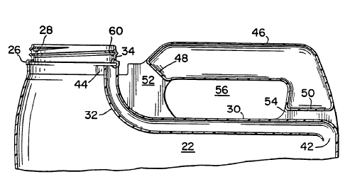
Figure 1 is a side elevational view of the
blow molded plastic bottle of the invention;
Figure 2 is a rear elevational view of the
bottle of Fig. l;
Figure 3 is a top plan view of the bottle of
Fig. l;
A


WO 95/15104 PGT/US94/03908
Figure 4 is a fragmentary sectional view of the bottle taken along
line 4-4 of Fig. 1;
Figure 5 is a fragmentary sectional view of the bottle taken along
line 5-5 of Fig. 1; and
Figure 6 is a fragmentary sectional view of the bottle taken along
line 6-6 of Fig. 3.
BEST MODE FOR CARRYING OUT THE INVENTION
The blow molded plastic container of the invention may be of
rectangular cross section and includes a bottom wall 12, side walls 14 and
16, front wall 18 and rear wall 20 extending vertically upwardly from
bottom wall 12 and defining a fluid containing chamber 22 which is closed
by top wall 24. A spout 26 extends upwardly from top wall 24 adjacent
front wall 18 and defines a circular pouring opening 28 through which the
liquid in chamber 22 may be poured from the bottle. A threaded cap (not
shown) normally closes opening 28 of spout 26.


WO 95/15104 PCTIUS94/03908
6
To prevent a glugging action as described hereinabove during a
pouring operation, a small diametered hollow vent tube 30 is molded
integrally on top wall 24 and extends horizontally from rear wall 20
forwardly to an upwardly curved front section 32 formed with opening 34
which opens upwardly into spout opening 28 at a rear portion 40 of spout
26. The rear end 42 of vent tube 30 opens downwardly into
communication with chamber 22.
A deflector ledge 44 extends transversely across the rear portion 40
of spout 26 directly adjacent tube opening 34.
An elongated hollow handle 46 of a size which is sufficiently large
to be comfortably and securely grasped is closed at both ends 48 and S0.
Thin pinched webbed sections 52 and 54 are integrally molded with and
between handle ends 48 and SO and the front and rear ends of vent tube
30. The webbed sections 52 and 54 mount the handle in spaced relation
from vent tube 30 and top wall 24 to form hand opening 56.
To pour liquid from chamber 22 hollow handle 46 is grasped to tip
bottle 10 forwardly. The liquid is deflected by ledge 44 away from the rear


WO 95/15104 PCT/US94/03908
7
edge 60 of spout 26 and vent opening 34 and over front edge 62. Air
enters opening 34 and passes through vent tube 30 and open rear end 42
into chamber 22 thereby preventing any glugging action. No liquid or air
enters hollow handle 46. Virtually all of the liquid that may enter vent
tube 30 during the pouring operation quickly drains back into chamber 22
when the bottle is placed upright. Because the diameter of tube 30 is so
small the amount of liquid which may remain in the tube is very small.
Consequently it presents no hazard upon disposal of the bottle.
In prior systems in which the substantially larger hollow handle
served as part of the vent passageway the amount of liquid which might
collect in the handle was substantially greater and, if it were a hazardous
chemical it could present a problem upon disposal of the empty bottle.
Also the fact that the handle is mounted directly on top of vent tube
30 ensures that during the pouring operation the liquid is poured over
front edge 62 and vent tube opening 34 remains open.
The invention may be embodied in other specific forms without
departing from the spirit or essential characteristics thereof. The present


WO 95/15104 PCTJUS94/03908
8
embodiment is therefore to be considered in all respects as illustrative and
not restrictive, the scope of the invention being indicated by the appended
claims rather than by the foregoing description, and all changes which
come within the meaning and range of equivalency of the claims are
therefore intended to be embraced therein.

Representative Drawing
A single figure which represents the drawing illustrating the invention.
Administrative Status

For a clearer understanding of the status of the application/patent presented on this page, the site Disclaimer , as well as the definitions for Patent , Administrative Status , Maintenance Fee  and Payment History  should be consulted.

Administrative Status

Title Date
Forecasted Issue Date 2001-12-04
(86) PCT Filing Date 1994-04-11
(87) PCT Publication Date 1995-06-08
(85) National Entry 1995-07-27
Examination Requested 1997-06-26
(45) Issued 2001-12-04
Deemed Expired 2007-04-11

Abandonment History

There is no abandonment history.

Payment History

Fee Type Anniversary Year Due Date Amount Paid Paid Date
Application Fee $0.00 1995-07-27
Registration of a document - section 124 $0.00 1996-02-29
Maintenance Fee - Application - New Act 2 1996-04-11 $100.00 1996-04-10
Maintenance Fee - Application - New Act 3 1997-04-11 $100.00 1997-04-10
Request for Examination $400.00 1997-06-26
Maintenance Fee - Application - New Act 4 1998-04-14 $100.00 1998-04-08
Maintenance Fee - Application - New Act 5 1999-04-12 $150.00 1999-04-06
Maintenance Fee - Application - New Act 6 2000-04-11 $150.00 2000-03-21
Maintenance Fee - Application - New Act 7 2001-04-11 $150.00 2001-03-20
Final Fee $300.00 2001-08-19
Maintenance Fee - Patent - New Act 8 2002-04-11 $150.00 2002-03-08
Maintenance Fee - Patent - New Act 9 2003-04-11 $150.00 2003-03-05
Maintenance Fee - Patent - New Act 10 2004-04-12 $250.00 2004-03-15
Maintenance Fee - Patent - New Act 11 2005-04-11 $250.00 2005-03-21
Owners on Record

Note: Records showing the ownership history in alphabetical order.

Current Owners on Record
RING CAN CORPORATION
Past Owners on Record
RING, CARL D.
Past Owners that do not appear in the "Owners on Record" listing will appear in other documentation within the application.
Documents

To view selected files, please enter reCAPTCHA code :


To view images, click a link in the Document Description column. To download the documents, select one or more checkboxes in the first column and then click the "Download Selected in PDF format (Zip Archive)" or the "Download Selected as Single PDF" button.

List of published and non-published patent-specific documents on the CPD .

If you have any difficulty accessing content, you can call the Client Service Centre at 1-866-997-1936 or send them an e-mail at CIPO Client Service Centre.


Document
Description 
Date
(yyyy-mm-dd) 
Number of pages   Size of Image (KB) 
Representative Drawing 2001-10-30 1 12
Description 1997-10-27 8 216
Claims 1997-10-27 2 63
Cover Page 1996-01-18 1 16
Abstract 1995-06-08 1 41
Description 1995-06-08 8 203
Claims 1995-06-08 2 38
Drawings 1995-06-08 4 80
Cover Page 2001-10-30 1 38
Representative Drawing 1998-07-10 1 10
Correspondence 2001-08-16 1 51
Assignment 1995-07-27 12 309
PCT 1995-07-27 1 54
Prosecution-Amendment 1997-06-26 6 155
Correspondence 2005-04-12 1 14
Fees 1997-04-10 1 46
Fees 1996-04-10 1 46