Note: Descriptions are shown in the official language in which they were submitted.
21 CiS3~
WO 94/lgl0g PCTIUS94/01608
APPARATUS AND METHOD OF AIR PURIFICATION
BACKGROUND OF THE INVENTION
Field of the Invention
The present invention related to air purification systems and related method and5 more particularly to an air purification system of the type that enhances filtration by
subjecting airborne con~min~nt~ to complex electrical fields.
Prior Art St~tement
Air purification systems of the type under consideration include a fixed output
power generator that produces a high voltage (HV) direct current and/or a high
10 frequency (HF) alternating current. The HV and HF autput from the power generator
is fed to separate electrodes. In large installations, electrodes are installed in an air
handling plenum, between the mixing box and cooling coils. In operation, the HV and
HF outputs generate a complex electrical field at the electrode assembly. All of the
air passing through the space being conditioned by the system, passes through this
15 complex electrical excitation field during primary and secondary air cycling. The
sub,--i~;-on particles tend to collide and adhere to each other and more rapidly increase
their mass. They are then more easily carried by the system air flow back through the
return to be captured in the filters or exhausted from th e building. The system thereby
enhances filtration and removal of airborne particles an~d gasses thus, reducing contami-
20 nants in a conditioned space.
As a result, air purification systems of this type save energy dollars by reducingthe need for large amounts of outside air, save initial inve~ len~ dollars by reducing
heating and cooling e~lui~ elll requi,e",ellt~., saves costs in the day-to-day cleaning
of the conditioned space and the cleaning and maintenance of the air h~n-lling equip-
25 ment. Air purification systems of this type also control the cont~min~nts such asoffensive dust, smoke and odor and thereby increase human efficiency by restoring
fresh, clean air to the interior environment in which we live, work and breathe.These systems operate effectively with no noise in the conditioned space. They
are also out of sight, thus rendering it difficult for anyone to irnmc~ tcly detect
30 interruption in the operation of the purification by the system. To handle this problem,
present power generators are equipped with an indicator, such as a light emitting diode,
to indicate if the generator itself is turned on and functioning electrically.
WO 94/19109 PCT/US94101608 _
21~53~6 2-
But in air purification systems of this type, in which cont~min~nts are subjected
to a complex electrical field as part of the purification process, many ambient condi-
tions, system parameters and type of cont~min~nts influence the efficiency and effec-
tiveness of the system. Thus, although the failure of the fixed output power generator
5 itself can be detected, the effective operation of other components of the system and
relevant ambient conditions cannot be readily detected. As a consequence, the air
purification system can be rendered ineffective; and such can only be detected by the
gradual recontamination of the air. During this time, the space reverts to the conditions
which prevailed prior to the utilization of the air purification system. Further, inas-
10 much as a period of time is required before an air purification system of this type canreduce the cont~min~nts to the O~)tilllUIII level, particularly in large installations, any
malfunctioning of a part of the system or change in operating conditions may create
an impure air quality condition that takes several hours or days to be removed com-
pletely, even after such malfunctioning has been noticed and remedied.
It has also been determined, that certain combinations of electrical field
characteristics work better than others in removing certain types of cont~min~tes from
the air. Thus, it is desirable to be able to pre-select electrical field characteristics and
independently of each other to maximize the air purification rate for a particular
application. Once the selection has been made, it is then desirable that such character-
20 istics be m~int~ineA
Each op~i~nulll electrical field characteristic should be maintained even thoughthe electrode screen assembly itself becomes contaminated or is otherwise subjected
to conditions that would affect the electrical characteristics on the electrodes and the
associated electrical field.
Wo 94/19109 21 ~ ~ 3 S 6 pcTlusg4lol6o8
SUMMARY OF THE INVE~TION
One of the objects of the present invention is to provide a self-regulating air
purification system and method that subjects air contaminants to a complex electrical
field characteristics, such as a DC voltage and an AC voltage and frequency that are
5 pre-selected independently of one another to provide op~hllulll conditions to influence
dirrele,-l types of cont~min~ntc.
Another object of the present invention is to provide an air purification systemhaving the capability of selfregulating electrical characteristics such as the DC voltage
and the AC voltage and frequency applied to the screen independently of one another.
A further object of the invention is to provide a self-regulating air purification
system which is relatively inexpensive to ".~inl~
Additional objects and advantages of the invention will be set forth in part in
the description which follows, and in part will be obvious from the description or may
be learned by practice of the invention. The objects and advantages of the invention
15 may be realized and obtained by means of the in~ulllenlalities and combinations
particularly pointed out in the appended claims.
In accordance with the purpose of the invention, as embodied and broadly
described herein, the air purification system of the present invention comprises a power
supply having an output for producing a predeterminecl voltage upon connection to an
20 AC input voltage; variable high DC voltage and high frequency circuit means respon-
sive to the output of the power supply for generating predetermined voltages andfrequencies in the kilovolt and kilohertz range; a conductive screen assembly electrical-
ly connected to the high voltage and high frequency circuit means and disposed in a
path of flowing air for subjecting the air to be purified to an electrical field of predeter-
25 mined voltage and frequency, the screen assembly conctituting an electrical load onthe high voltage and high frequency circuit means; and means for varying both the DC
voltage and the AC voltage and frequency independently of each other.
In another aspect, the method of the present invention, as embodied and broadly
described herein, comprises flowing the air to be purified through a conductive screen
30 assembly, increasing the amplitude of an input voltage for applying a high voltage in
the kilovolt range and high frequency in the kilohertz range to the screen assembly to
Wo 94tl9109 215 S 3~ ~ PCT/US94/01608
.; ., .
subject the air flowing through the screen to a complex electrical field; adjusting the
m~gnit~lde of the DC voltage and the AC voltage and frequency independently of each
other; detecting the m~gnitude and frequency of the voltage of the screen assembly;
and controlling at least one of the field characteristics of the applied voltage in
5 accordance with the detected voltage.
The accompanying drawings which are incorporated in and constitute a part
of this specification, illustrate two embodiments of the invention, and together with
the description, serve to explain the principles of the invention.
~ 94/lglO9 . 1~ PCTIUS94/01608
BRIEF DESCRIPTION OF THE DRAWINGS
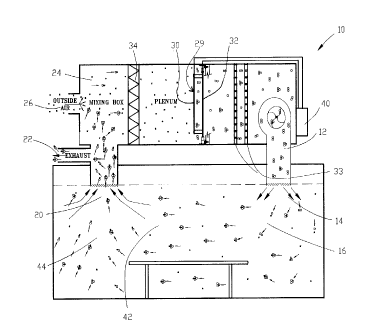
Fig. 1 illustrates one of the arrangements of the individual parts of an air
purification system relative to the area being purified,, together with a dia~ ""n~ti~
illustration of the airbome contamin~nt~;
S Fig. 2 is a schematic block diagram of a self-regulating system of the present
invention capable of maintaining preselected electrical characteristics independently
of one another;
Fig. 3A is a block diagram of the DC power supply for the system;
Fig. 3B is a block diagram of an exemplary adjustable HV module;
Fig. 3C is a block diagram of the adjustable H:F module;
Fig. 4 is a block diagram of an analog implerrlentation of the system;
Fig. S is a block diagram of a digital/microprocessor implementation of the
system; and
Fig. 6 is an illustration of the inductive sensin,g means.
wo 94/19109 2~ j~3S 6 PCT/US94101608 --
DETAILED DISCUSSION
Reference will now be made in detail to the present preferred embodiments of
the invention, an example of which is illustrated in the accompanying drawings.
Referring to Fig. 1, an air purification system of the present invention prefera-
5 bly, comprises a means for flowing the air to be conditioned or purified. As embodiedherein, an air plenum 10 that includes a supply air fan 12 flows the air into a room
generally referred to at 14. The flowing air, which includes co~ ,..in~nt~ such as 16,
is flowed along a path and circulated through a passage 20 where a certain portion of
the air is exhausted through outlet 22 and another portion of which enters a mixing
portion 24 of air plenum 10 which mixes with outside air through inlet 26. In the path
of the flowing air is a screen assembly 29. Although the air purification is illustrated
and described in connection with a conditioned space having an air plenum, it isunderstood that the conditioned purified air may make a single pass through the
conditioned space or may discharge directly into the atmosphere, as in an exhaust stack
or air purge system.
The present invention includes a screen assembly disposed in the path of the
air to be treated and electrically connected to a system for creating a complex electrical
field from direct current and ~ltern~ting current inputs. As embodied herein, a screen
assembly 29 comprises a high voltage electrode 30 and a high frequency electrode 32.
The electrodes 30 and 32 may include movable grids or selectively engaged areas for
controlling the degree of tre~tm-qnt. It is understood that the electrodes may also be
in the form of conductive wire mesh, rods, braid, or other types of conductors in other
geo~lc;l ic configurations.
As illustrated, the system of the present invention may also include an air filter
34 mounted in air plenum 10 upstream of electrodes 30 and 32, with cooling or heating
coils 33 mounted in the plenum downstream of electrodes 30 and 32. An air filter may
also be mounted downstream of electrodes 30 and 32 in the system prior to discharge
into the room 14.
With reference to Fig. 1, as the air passes through the complex electrical fieldgenerated at electrodes 30 and 32, smaller particles begin to coalesce or coagulate
rapidly as shown between electrode 32 and coils 33. These small particles grow larger
wo 94,lgl09 2~r~ PCT/US94/01608
7- ~3~S~
and larger as they pass through the conditioned space to the return air duct at passage
20 as indicated, for example, by clusters 42 and 44. ]n one situation, it was shown
that there was a 367% increase in large particle mass ~vith 94% of the particle mass
involved removed from the conditioned area. These large particle clusters, such as 42
S and 44, are then either exh~ tecl through opening 22 or mixed with dirty untreated
outside air entering through inlet 26 into the mixing box 24 and are readily collected
by medium or high efficiency filter 34. For most applications, such filters may have
an efficiency rating of approximately 55%. In certain specific applications, such as
data processing centers, casino's and medical facilities filters 34 may require an
efficiency in the neighborhood of 80% or better. The fi~ltered air, which still contains
millions of fine particles, then passes through electrodes 30 and 32, and the purification
cycle begins again, significantly reducing the airborne dust, smoke, gases and odors
in the conditioned space.
Referring to Fig. 2, the air purification system of the present invention, as noted
40, has a DC power supply 50, an AC power input 52, and an output 54 connected
to a variable high voltage (HV) DC circuit 56 having an output 58 and a variable high
frequency (HF) AC circuit 60 having an output 62. Screen assembly 29, that includes
high voltage (HV) electrode 30 and high frequency (HF) electrode 32 as previously
described, is connected to output 58 and 62 of circuits 56 and 60 respectively. A high
voltage (HV) sensor 64 has an input 66 connected to high voltage (HV) electrode 3
0; and an AC high (HF) voltage and frequency sensor 68 and 68' and have inputs 70
and 70' connected to high frequency (HF) electrode 32. Output 72 of high voltagesensor 64 is connected to an HV control circuit 74; and outputs 76 and 76' of AC high
voltage and frequency sensors 68 and 68' are connected to control circuits 78 and 78'.
HV control circuit 74 has an output 80 connected to an input of variable high voltage
DC circuit 56; and HF control circuit 78 and 78' have outputs 82 and 82' connected
to the inputs of variable high frequency circuit 60. A high voltage (HV) parameter
selection circuit 88 has an output 90 connected to control circuit 74. The high frequen-
cy (HF) parameter selection circuit 84 and 84' have outputs 86 and 86' connected to
control circuits 78 and 78'.
Although Fig. 2 illustrates a system that includes the self-regulation of both the
high frequency and high voltage circuits with the parameter selections of each indepen-
W O 94/19109 2 15 5 3 ~ ~ PCTrUS94/01608 -
dent of one another; for some applications the system could be advantageously utilized
with the self regulation of the high voltage circuit without the self regulation of the
high frequency circuit or vice versa.
Once the set point is obtained, the complex electrical field is optimized for a
5 particular contaminant or cont~min~nt~, it is desirable to m~int~in that condition,
however envil o~""el,lal factors such as temperature, humidity and concentration or type
of col~l~"~i"~nt may change, causing the complex electrical field's effectiveness to
rlimini~h The objective of the invention is to compensate for the environmtont~l factors
and thereby m~int~in opLill,ul" efficiency.
The system of the present invention comprises a power supply having an output
for producing a DC voltage with 2 predetermined amplitude upon connection to an AC
input. As embodied herein and referring to Fig. 3A, power supply 50 has an inputtran~rolmel 51 to set the proper AC voltage levels. Power supply 50 also includes
rectifiers 53 and voltage regulators 55 to produce the proper DC levels for operation
of the HV, HF, and control cihl;uilly.
In accordance with the present invention, a variable high voltage circuit is
electrically coupled to the power supply for generating a variable DC high voltage in
the kilovolt range. As embodied herein and shown in Fig. 3B, high voltage circuit 56
has an oscillator 57, a transformer 59 and a voltage multiplier and rectifier 61. The
oscillator, being a primary signal source, produces a voltage which is transformed to
the proper AC level by the tran~rol",el. The voltage multiplier takes the output of the
transformer, shifts the level by the proper multiple, and changes the AC to a DCvoltage. This voltage is in the DC kilovolt range and is applied to the HV electrode
30.
In accordance with the present invention, a variable high frequency circuit is
electrically coupled to the power supply for generating a high frequency output in the
kilohertz range. As embodied herein and referring to Fig. 3C, high frequency circuit
60 has an oscillator 67 and a transformer 63 capable of operating in the RF range of
frequencies. The oscillator, being a primary signal source, produces a voltage. This
voltage is coupled to the tran~rol"-e, which raises the voltage to the proper AC level.
This voltage is in the range of hundreds of volts RMS at a frequency in the kilohertz
range. This voltage is applied to the HF electrode 32.
Wo 94/19109 ~5'S3S~ PCT/US94/111608
Thus, the variable high frequency circuit 60 and the variable high voltage circuit
56 have similar components and function. It should be noted that the secondary
winding of the transformer and the capacitive load represented by the screen assembly
29 form a tuned circuit, the impedance of which is frequency dependent. If the
operating frequency of the circuit 60 is adjusted to be close to the resonant frequency,
the current in the primary winding of corresponding tr~m~ro~ l 63 is low. However,
it increases rapidly as the operating frequency moves from resonance. Thus, the output
voltage of circuit 60 is dependent upon the operating i`requency of the corresponding
oscillator 67. The output voltage on 62 peaks when the corresponding circuit 60 is
operating at resonance, and will decrease as the oscillator frequency moves away from
resonance. A current limiting regulator (not shown) is provided to limit the current
to an acceptable maximum value under off design conditions which can occur during
start-up, or if the frequency is improperly adjusted.
As previously mentioned, the conductive screen assembly 29 is electrically
connected to the high voltage circuit 56 by line 58, an,d the high frequency circuit 60
by line 62, and disposed in the path of the flowing air to subject the air to be purified
to a complex electrical field having a predetermined high voltage and high frequency
applied. The screen assembly 29 con~titutes a capacitive load on the high voltage
circuit 56 and high frequency circuit 60.
In accordance with the invention, one embodiment has a high voltage sensor
coupled to the screen assembly for outputting a voltage having an amplitude corre-
sponding to the voltage imposed on the screen assembly by the high voltage circuit
and HF voltage and frequency sensors for outputting a voltage having an amplitude
corresponding to the RMS voltage and frequency of ~the HF electrode of the screen
assembly. As herein embodied, a voltage sensor 64 is connected to the high voltage
(HV) screen 30, HF voltage and frequency sensors 68, and 68' respectively are
connected to HF screen 32.
The system of the present invention includes a voltage control circuit connecting
the variable DC high voltage circuit to the HV voltage sensor. In this way, it is possi-
ble to m~int~in a constant predetermined level of the complex electrical field at the
screens. As herein embodied and referring to Fig. 4 an analog system in accordance
WO 94/19109 ,;~ 35~ PCT/US94/01608
with the present invention is described. The HV control circuit, produces an output
voltage on line 80 for controlling the frequency of oscillator 57 in HV circuit 56.
The output of the sensor 64 is a voltage level that is proportional to the levelof voltage on the HV electrode 30. This voltage level on line 72 is compared to a
5 reference voltage level (set point) on line 90 by the HV control circuit 74. The output
of HV control circuit 74 on line 80 is an error signal which represents the dirrt;lt;nce
be~e~,n the actual electrode voltage on screen 30 and the desired electrode voltage.
The output of the HV control circuit 74 on line 80 is an input to the high voltage DC
circuit 56 shown in Fig. 3B. The amount of error voltage input to the high voltage
lO circuit 56 will adjust the output voltage level of the oscillator 57 which will determine
the voltage level applied to the HV electrode 30. In this way, the HV electrode voltage
will be kept at the desired level.
The system of the present invention also includes HF control circuits 78 and
78' connecting the variable AC high frequency circuit 60 to the HF sensors 68 and
15 68' for varying the frequency and amplitude of the voltage applied to electrode 32 of
screen assembly 29 in accordance with the frequency and amplitude of the output
voltage of sensors 68 and 68' ~sl)eclively, to m~int~in a cons~llt predeterminedfrequency and amplitude of the complex electrical field.
HF voltage and frequency sensors 68 and 68' are coupled to the screen assem-
20 bly for outputting a voltage having an amplitude corresponding to the frequency andamplitude imposed on the screen assembly by HF circuit 60. As shown in Fig. 4, the
output of the HF amplitude sensor 68 is a voltage level that is proportional to the
amplitude of the voltage on HF electrode 32. This voltage level on line 76 ia com-
pared to a reference voltage level (set point) by an HF amplitude control circuit 78.
25 The output of the HF amplitude control circuit 78 on line 82 is an error signal which
represents the difference between the actual electrode voltage amplitude and the desired
electrode voltage amplitude.
The output of the HF frequency sensor 68' is a voltage level proportional to
the frequency of the voltage on HF electrode 32. This voltage level on line 76' is
30 col~ )ared to a reference voltage level (set point) by the HF frequency control circuit
78'. The output of the HF frequency controi circuit 78' on line 82' is an error signal
wo ~4/1~10~ 2~ PCT/US94/01608
which represents the difference between the actual electrode voltage frequency and the
desired electrode voltage frequency.
Referring again to Figs. 2 and 4, HF amplitude parameter selection circuit 84
has an output 86 for connecting an output voltage corresponding to a reference or set
5 point voltage for comparison with the corresponding sensed voltage from the HFvoltage sensor 68 of electrode 32. HF frequency parameter selection circuit 84' has
an output 86' for connecting an output voltage corresponding to a reference or set point
voltage for comparison with the col.e~l,onding sensed voltage from the HF frequency
sensor 68' of electrode 32. The paldlllt;~t;l selection circuit 84 provides a set point on
10 86 for setting the desired amplitude set point for the AC voltage of electrode 32 and
circuit 84' provides a set point on 86' for setting the desired frequency of the AC
voltage of electrode 32. HV parameter selection circuit 88 has an output 90 for
connecting an output voltage corresponding to a reference or set point voltage for
compaTison with the corresponding sensed voltage from the HV sensor 64. The
15setpoints of the ~ lel~- selection circuits 88, 84 and 84' are independently adjust-
able. The circuits 88 and 84 and 84' can provide for manually adjustable set points.
Several means can be used to select the HF and HV set points. For example,
a microprocessor could be used. An additional concept would involve using a sensing
device in the air stream which would sense the presence of certain cont~min~nt.~, and
20then make adju~menl to the power supply to maximize the efficiency of the unit for
each of these particular con~ "l~. Voltage levels could also be adjusted to follow
airflow rates in the duct, for example.
Referring to Fig. 5, a digital implementatian of the system of the present
invention comprises an HV sensor 64, an amplitude sensor 68 and a frequency sensor
2568', electrically coupled to HV electrode 30 and HF electrode 32. An HV module 56
and an HF module 60 are connected to electrode 30 and 32 .,s~ e~ /ely for providing
a variable DC and variable AC voltage to the electrodes similar to the previously
described embodiment. The system further includes an A/D converter 100 connectedto the output of sensor 64, and an A/D converter :102 connected to the outputs of
30sensors 68 and 68'. A D/A converter 104 has an output connected to the input of HV
module 56. A microprocessor 108 has an input connected to the A/D converter 100
WOg4/19109 2~5535~ 12 PCT/US94/01608 --
and an output connected to the D/A converter 104. A microprocessor 110 has an input
connected to the A/D converter 102 and an output connected to the D/A converter 106.
Referring again to Fig. 5, the HV and HF electrodes are located in the air
stream for the purpose of creating a complex electrical field. The complex electrical
S field is detected by the sensors 64, 68 and 68'. A/D converters 100 and 102 each
produce a digital signal. The digital signal from A/D converter 100 is proportional
to the DC level of the voltage on the HV electrode 30, and the digital signal from the
A/D converter 102 is proportional to the AC frequency and amplitude of the signal
on the HF electrode 32. The digital signals are each applied to an input port of a
respective microprocessor 108 and 110. The inputs are processed by the corresponding
microprocessor using instructions which are stored in memory units 114 and 116 (RAM
and ROM) which are also interfaced to the le~e~-Live microprocessor. Each micropro-
cessor outputs information to separate display circuitry 117 and 118, interface chcuilly
(RS-232, etc.) 120 and 122, and to two sepald~e D/A converters 104 and 106. D/A
converter 104 is connected to HV module 56 which is a high voltage generator capable
of producing a DC voltage in the kilovolt range. The output of this D/A converter 104
will control the amount of voltage produced by the high voltage DC generator, the
output of which is connect~d to the HV electrode 30. The output of the D/A converter
106 will control the frequency and amplitude of the AC voltage, produced by the high
voltage AC generator, which is connected to the HF electrode 32.
Fig. 6 shows an alternate ~ us for sensing the amplitude and frequency
of the complex elec~ gnetic field associated with electrodes 30 and 32. In this
embodiment an inductive pick-up coil 130 disposed in the complex electrical field
created by electrodes 30 and 32 of the screen assembly 29, replaces sensors 64, 68 and
68'. The inductive pick-up coil will sense the lines force generated by the electrical
field. These lines of force are proportional to the m~gnit~lde and frequency of the
electrical field generated by the screen assembly 29. The lines of force will induce
a voltage into the inductive pick-up which may be connected to any well known
amplifier and signal processor for detecting the RMS value, frequency and peak
electrical strength of the field. These signals are then output to a co-llL,~ator for an
analog system or an A/D converter for the digital system. Although three separate
sensors are shown and described in connection with Figs. 4, it is to be understood that
Wo 94/19109 '`~3Sf~ PcTn~sg4ml6o8
a single inductive pick-up coil may be used to detect tlhe effect of the DC voltage, and
AC amplitude and frequency for the HV and H~ circuits, respectively.
It will be apparenl to those skilled in the art that various modifications and
variations can be made in the air purification system of the present invention without
5 departing from the spirit or scope of the appended claims. Thus, it is intended that
the present invention covers the modifications and variations of this invention provided
they come within the scope of the appended claims and their equivalents.