Note: Descriptions are shown in the official language in which they were submitted.
-1- C~~~155~95
Title of the Invention:
PHOTOGRAPHIC FILM
Background of the Invention:
The present invention relates to a photographic film and,
particularly, to a photographic film that can be easily cut into individual
screens.
Description of the Prior Art:
1 o Photographic filins of a variety of kinds of shapes have
hitherto been developed. In recent years, a perforated filin having a width
of 35 mm has been used most extensively.
For example, referring to a conventional filin having a
width of 35 mm which is obtained by developing a positive film for slide,
the film of a width of 35 mm has holes perforated in an opposing manner
along both side portions thereof in the direction in which it is fed. These
holes have nearly a rectangular shape and the long sides of the holes are
oriented in the direction of width of the film. On the filin are
photographed screen portions, and gap portions are provided among these
2 o screen portions. To divide the film into individual screens, therefore,
the
gap portions are cut along the centers thereof using a pair of scissors such
that a film of one screen is formed.
This one-screen film is fitted onto a slide mount which is
constituted by a mount and a cover that are made of, for example, a
2 5 plastic material. This mount is provided with a film-placing portion
which has a size nearly equal to the size of a screen and forms a step with
respect to the surface of the mount. A window is opened at the central
portion of the filin-placing portion. Furthermore, recessed portions are
formed in the periphery of the film-placing portion, and the outer
3 o peripheries of these recessed portions are formed in a protruding manner.
A window is formed in the aforementioned cover, and protruded portions
are provided on the periphery of this last-mentioned window. By fitting
the protruded portions into the recessed portions of the mount, the mount
and the cover are firmly fitted together; i.e., the windows are
3 5 superimposed one upon the other to form the slide mount.
A
~~ ~ 1 ~~~9~
The film that is cut into a into a unit of screen is placed on
the film-placing portion and, then, the mount and the cover are fitted
together so that the film is fitted onto the slide mount.
In the conventional filin, holes are formed in an opposing
manner in both side portions of the filin in a direction in which it is fed.
The holes are perforated in a number of, for example, eight for one screen
in both side and portions thereof maintaining an equal distance. When a
picture is taken by using the above film as a positive film for slide,
portions near the gaps of the film may often be developed into a dark
color depending upon the subject that is photographed. When the filin is
to be cut into individual screens, therefore, it becomes very difficult to
confirm by naked eyes the gap portions among the screens, often causing
the film to be cut at incorrect positions. Moreover, even when the holes
on both sides of the film are so set as to be located at the gap portions in
taking a photograph on the film, the distance among the holes are so
narrow that a neighboring pair of opposing holes may be erroneously
regarded to be the aimed pair of opposing holes resulting in an incorrect
cutting of the film.
To fit the film onto the slide mount, furthermore, the film is
2 o placed on the filin-placing portion formed in the mount of the slide
mount. The filin-placing portion in the direction of width is set to be in
agreement with a specified value of the film, e.g., 35 mm and is, hence,
correctly placed in position. On the other hand, the film is cut by hand
into a size in the lengthwise direction thereof which makes it difficult to
2 5 cut the film maintaining a predetermined size. Therefore, the film-placing
portion has a size in the lengthwise direction thereof which is larger than
the size of one screen. Accordingly, the filin that is inserted in the slide
mount has a margin in the feeding direction and may undergo a deviation
in position.
3 0 Therefore, there arouse technical problems in regard to
cutting the filin into individual screens at correct positions and in regard
to correctly fitting the film that is cut into a screen onto the slide mount.
The object of the present invention is to solve these problems.
-3-
Summary of the Invention:
The present invention was proposed in order to achieve the
above object, and provides a photographic film in which holes are
perforated in both side portions of the film in a direction in which it is
fed, the holes being opposed to each other at gap portions among the
photographed screens, as well as a photographic film in which the holes
that are perforated therein have nearly an elliptic shape, the long sides
thereof being oriented in the direction in which said film is fed.
According to the invention, holes are perforated in an
opposing manner in both side portions of the film in a direction in which
it is fed, and the pair of holes are arranged over the distance of gap
portion between the photographed screens of the film. Therefore, if the
picture is so taken that the pair of holes come into agreement with the
center of the gap portion between the screens, then, the film can be
divided into individual screens by cutting the film along a line that
connects the centers of the pair of holes.
According to the invention, the holes formed in both side
portions of the film are elongated in a direction in which the film is fed so
as to serve as a distinct target for cutting the filin into the screens. The
2 o ends of the holes in the lengthwise direction are semicircularly formed
contributing to increasing the ranges that come into contact with the
positioning pins of the slide mount.
Therefore, in accordance with the present invention, there is
provided a photographic film comprising:
2 5 a plurality of screen portions extending longitudinally along
the photographic film;
a plurality of gap portions formed between each of said
plurality of screen portions, said plurality of gap portions each having a
longitudinal axis laterally extending across the photographic film; and
3 o the photographic film having opposing longitudinal side
portions, the opposing longitudinal side portions having a plurality of
elliptical holes formed therein, the plurality of elliptical holes each having
a longitudinal axis, the longitudinal axis of each one of the plurality of
elliptical holes intersecting and being substantially perpendicular to the
3 5 longitudinal axis of a respective one of said plurality of gap portions,
such
that the plurality of elliptical holes are elongated in a direction in which
A
~;~~2~ 55~~~
-4-
the photographic film is fed, and positioned only over said plurality of
gap portions,
whereby laterally opposing pairs of the plurality of elliptical
holes serve as a distinct target for cutting the film into individual screen
portions.
Also in accordance with the present invention, there is
provided a photographic filin in which holes are perforated in both side
portions of the film in a direction in which it is fed, the holes being
opposed to each other at gap portions among the photographed screens.
Brief Description of the Drawings.
Fig. 1 is a plan view of a filin which illustrates an
embodiment of the present invention;
Fig. 2 is a plan view thereof illustrating the state in which
the photographed film is developed;
Figs. 3(a) and (b) are plan views illustrating the state in
which the film cut into a screen is placed on a slide mount and in the case
of Fig. 3(b), with the cover closed;
Fig. 4 is a plan view of a film according to a prior art;
2 p Fig. 5 is a plan view showing the shape of the film cut into
a screen according to the prior art; and
Fig. 6 is a plan view illustrating the state in which the film
is placed on a slide mount according to the prior art.
2 5 Detailed Description of Preferred Embodiments
Photographic films of a variety of kinds of shapes have
hitherto been developed. In recent years, a perforated film having a width
of 35 mm has been used most extensively.
Fig. 4 illustrates a conventional film 1 having a width of 35
3 o mm which is obtained by developing a positive filin for slide. The film 1
has a width of 35 mm and has holes 2 perforated in an opposing manner
along both side portions thereof in the direction in which it is fed. The
holes 2 have nearly a rectangular shape and the long sides of the holes 2
are oriented in the direction of width of the filin 1. On the film 1 are
3 5 photographed screen portions 3, and gap portions 4 are provided among
the screen portions 3. To divide the film into individual screens,
~-. _
.~4
-S- v~,2155
therefore, the gap portions 4 are cut along the centers thereof using a pair
of scissors; i.e., a film 5 of one screen is formed as shown in Fig. 5.
Fig. 6 illustrates a state where the filin 5 is fitted onto a
slide mount 6 which is constituted by a mount 7 and a cover 8 that are
made of, for example, a plastic material. The mount 7 is provided with a
film-placing portion 9 which has a size nearly equal to the size of a screen
and forms a step with respect to the surface of the mount 7. A window 10
is opened at the central portion of the filin-placing portion 9.
Furthermore, recessed portions 11 are formed in the periphery of the filin-
1 o placing portion 9, and the outer peripheries of the recessed portions 11
are formed in a protruding manner. A window 12 is formed in the cover
8, and protruded portions 13 are provided on the periphery of the window
12. By fitting the protruded portions 13 into the recessed portions 11 of
the mount 7, the mount 7 and the cover 8 are firmly fitted together; i.e.,
the window 12 and the window 12 are superimposed one upon the other
to form the slide mount 6.
The film 5 that is cut into a unit of screen is placed on the
film-placing portion 9 and, then, the mount 7 and the cover 8 are fitted
together so that the film 5 is fitted onto the slide mount 6.
2 o In the conventional film, holes are formed in an opposing
manner in both side portions of the filin in a direction in which it is fed.
The holes are perforated in a number of, for example, eight for one screen
in both side portions thereof maintaining an equal distance. When a
picture is taken by using the above film as a positive filin for slide,
2 5 portions near the gaps of the film may often be developed into a dark
color depending upon the subject that is photographed. When the film is
to be cut into individual screens, therefore, it becomes very difficult to
confirm by naked eyes the gap portions among the screens, often causing
the film to be cut at incorrect positions. Moreover, even when the holes
3 0 on both sides of the film are so set as to be located at the gap portions
in
taking a photograph on the film, the distance among the holes are so
narrow that a neighboring pair of opposing holes may be erroneously
regarded to be the aimed pair of opposing holes resulting in an incorrect
cutting of the film.
3 5 To fit the filin onto the slide mount, furthermore, the film is
placed on the film-placing portion formed in the mount of the slide
A
C,~~~ ~ 55395
-6-
mount. The filin-placing portion in the direction of width is set to be in
agreement with a specified value of the film, e.g. 35 mm and is, hence,
correctly placed in position. On the other hand, the film is cut by hand
into a size in the lengthwise direction thereof which makes it difficult to
cut the filin maintaining a predetermined size. Therefore, the filin-placing
portion has a size in the lengthwise direction thereof which is larger than
the size of one screen. Accordingly, the film that is inserted in the slide
mount has a margin in the feeding direction and may undergo a deviation
in position.
1 o Therefore, there arouse technical problems in regard to
cutting the film into individual screens at correct positions and in regard
to correctly fitting the film that is cut into a screen onto the slide mount.
The object of the present invention is to solve these problems.
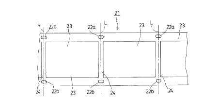
Accordingly, an embodiment of the present invention will
now be described in detail with reference to Figs. 1 to 3. Fig. 1 illustrates
a photographic film 21 having holes 22a and 22b that are perforated in an
opposing manner in both side portions of the film 21 in a direction in
which it is fed. The holes 22 a and 22b have an elliptic shape and a width
that is equal to the diameter of positioning pins that will be described
2 0 later. Fig. 2 illustrates a state in which are developed photographs taken
on the film 21 which is a positive filin for slide by using a camera. Here,
the camera in which the film 21 is loaded to take pictures is equipped
with a mechanism that brings the lines L, connecting the centers of the
holes 22a and 22b formed in an opposing manner in the film 21 into
2 5 agreement with the center lines of the gap portions 24 provided among the
screen portions 23.
If the film 21 is cut by using a pair of scissors along the
lines L connecting the opposing holes 22a, 22b, then the screen portions
23 of the filin 21 are cut along the center of the gap portions 24 at both
3 o ends of each of the screen portions 23. Thus, the filin is divided into
individual screens.
Figs. 3(a) and 3(b) illustrate the state in which a film 31
divided into the screens is fitted onto a slide mount 32. The slide mount
32 is constituted by a mount 33 and a cover 34 in which are perforated
3 5 windows 35 and 36, respectively. As shown in Fig. 3(a), pole-like
positioning pins 38 are studded at positions corresponding to holes 37 on
_7_ ~~~~ ~~~~~5
both sides of the film 31 at four corners of the window 35 of the mount
33.
As shown in Fig. 3(b), furthermore, positioning holes 39 are
formed in the cover 34 at positions where the positioning pins 38 come
into engagement. To place the film 31 on the slide mount 32, the holes
37 of the film 31 are brought into engagement with the positioning pins
38 of the mount 33, so that the semicircular portions of the holes 37 and
the side portions of the positioning pins 38 are fitted to each other. Then,
the cover 34 is placed on the mount 33, and the positioning pins 38 and
the positioning holes 39 are engaged with each other, so that the film 31
is correctly fitted onto the slide mount 32. The screen portion 40 of the
film 31 is disposed on the inside of the windows 35 and 36 of the slide
mount 32 and is not hindered by the windows 35 and 36.
Though the holes 22a, 22b and 37 formed in the films 21
and 31 were of an elliptic shape in this embodiment, the same effects can
be exhibited even when the holes 22a, 22b and 37 have a rhombic shape
or an oval shape provided both ends of these holes in the feeding
direction have a nearly semicircular shape.
The present invention can be modified in a variety of other
2 0 ways without departing from the spirit and scope of the invention, and it
should be noted that the present invention encompasses even those
modified embodiments as a matter of course.
According to the invention as described in detail in the
foregoing embodiment, holes are perforated in an opposing manner in the
2 5 gap portions that are provided among the screens in both side portions of
the film in a direction in which it is fed. Therefore, cutting positions
among the screens can be correctly set along the lines that connect the
centers of the holes. Thus, the film can be cut easily and quickly into the
individual screens.
3 o According to the invention in which the ends of the holes
formed in both side portions of the film have a semicircular shape in the
feeding direction, the pole-like positioning pins of the slide mount come
into engagement in an inscribing manner with the holes of the film when
the filin that is divided into the screens is fitted onto the slide mount.
3 5 Therefore, the contacting point between the hole and the positioning pin
is expanded as much as possible, enabling the film to be fitted onto the
slide mount or the like firmly and correctly.
Cr~215~5395
Moreover, since the holes of the filin have a rectangular
shape in the direction of width of the film, it is allowed to expand the
picture-taking area of the film and the film can be efficiently utilized.
When the size of the photographic screen is maintained to be the same as
5 that of the prior art, furthermore, the width of the film can be shortened,
exhibiting various effect such as enabling the outer size of the film to be
decreased.