Language selection

Search

Patent 2155504 Summary

Third-party information liability

Some of the information on this Web page has been provided by external sources. The Government of Canada is not responsible for the accuracy, reliability or currency of the information supplied by external sources. Users wishing to rely upon this information should consult directly with the source of the information. Content provided by external sources is not subject to official languages, privacy and accessibility requirements.

Claims and Abstract availability

Any discrepancies in the text and image of the Claims and Abstract are due to differing posting times. Text of the Claims and Abstract are posted:

  • At the time the application is open to public inspection;
  • At the time of issue of the patent (grant).
(12) Patent Application: (11) CA 2155504
(54) English Title: GROUND ANCHOR
(54) French Title: DISPOSITIF D'ANCRAGE AU SOL
Status: Deemed Abandoned and Beyond the Period of Reinstatement - Pending Response to Notice of Disregarded Communication
Bibliographic Data
Abstracts

English Abstract


A ground anchor comprises an elongate body with a flight at a
lower end of the body. The flight is a length of 24 inches and the elongate
body a length of the order of 8 feet and is formed by two tubes arranged end
to end coupled by a cylindrical sleeve pinned to the adjacent ends of the tubes.A winged stabilizer assembly includes a sleeve over an upper end of the
tubular body. The stabilizer assembly is clamped downwardly into the ground
by a nut welded to a threaded rod which engages into a second nut welded to
the top of the tube. The threaded rod is thus supported vertically upwardly
from the top of the tube and supports a mounting assembly. The mounting
assembly comprises a bracket having a base plate and a mounting plate
parallel to the base plate with a sleeve therebetween for receiving the upper
end of the threaded rod. A nut carries the mounting plate adjustably on the
threaded rod. A support plate parallel to the mounting plate is carried on a
second nut on the threaded rod. The mounting plate and the support plate are
clamped together by a pair of bolts parallel to the threaded rod.


Claims

Note: Claims are shown in the official language in which they were submitted.

CLAIMS
1. A ground anchor for engagement into the ground
comprising an elongate body having a longitudinal axis, a flight attached to thebody around the axis adjacent a lower end thereof, engagement means on the
body for engaging a handle for drivingly rotating the body about the axis for
threading the flight into the ground, and mounting means as an upper end of
the body for engaging a member to be supported relative to the ground, the
elongate body comprising a tube.
2. The ground anchor according to Claim 1 wherein the
elongate body comprises two separate tubes coupled end to end.
3. The ground anchor according to Claim 2 wherein the two
separate tubes are coupled by a cylindrical body projecting into the adjacent
ends of the tubes and a pair of transverse pins each coupling the cylindrical
body to a respective one of the tubes.
4. The ground anchor according to Claim 1 wherein the
mounting means comprises a nut welded to the upper end of the body and
defining a vertical threaded bore and a threaded rod for engagement into the
bore.
5. The ground anchor according to Claim 4 wherein the
threaded rod extends through the nut into the upper end of the tube.
6. The ground anchor according to Claim 4 wherein the
threaded rod has a nut welded thereto at a position partly along the length of
the threaded rod such that rotation of the nut threads the threaded rod into thenut on the end of the body.
7. The ground anchor according to Claim 6 including a
stabilizer assembly having a sleeve for surrounding the upper end of the body
and a plurality of wings extending outwardly from the sleeve generally radially
to the axis, the sleeve having a top plate for surrounding a threaded rod and

7
for engaging the nut welded to the threaded rod for driving the stabilizer
assembly downwardly onto the top of the elongate body.
8. The ground anchor according to Claim 4 wherein the
mounting means further includes a mounting a bracket for attachment to the
member having a base plate, a sleeve attached to an underside of the base
plate and extending downwardly therefrom and a support plate parallel to the
base plate, the threaded rod extending into the sleeve, and a nut engaged on
the threaded rod for supporting the mounting plate, the height of the mounting
plate and the bracket on the threaded rod being adjustable by the nut so that
the length of the threaded rod extending into the sleeve varies in dependence
upon the position of the nut on the threaded rod.
9. The ground anchor according to Claim 8 wherein the
mounting means further includes a second plate parallel to the first mounting
plate, a second nut supporting a second plate and at least two nut and bolt
fasteners spaced radially outwardly from the threaded rod and interconnecting
the second plate and the mounting plate.
10. The ground anchor according to Claim 1 wherein the
engagement means comprises a transverse hole through the body for engaging
a horizontal pin.
11. The ground anchor according to Claim 10 wherein the
handle comprises a horizontal pin and an elongate member coaxial with the pin
and extending longitudinally therefrom.
12. The ground anchor according to Claim 1 wherein the flight
has an axial length of the order of 24 inches.
13. A ground anchor for engagement into the ground
comprising an elongate body having a longitudinal axis, a flight attached to thebody around the axis adjacent a lower end thereof, engagement means on the
body for engaging a handle for drivingly rotating the body about the axis for

threading the flight into the ground, and mounting means as an upper end of
the body for engaging a member to be supported relative to the ground,
wherein the mounting means comprises a nut welded to the upper end of the
body and defining a vertical threaded bore and a threaded rod for engagement
into the bore.
14. The ground anchor according to Claim 13 wherein the
mounting means comprises a nut welded to the upper end of the body and
defining a vertical threaded bore and a threaded rod for engagement into the
bore.
15. The ground anchor according to Claim 14 wherein the body
comprises a tube and wherein the threaded rod extends through the nut into
the upper end of the tube.
16. The ground anchor according to Claim 14 wherein the
threaded rod has a nut welded thereto at a position partly along the length of
the threaded rod such that rotation of the nut threads the threaded rod into thenut on the end of the body.
17. The ground anchor according to Claim 16 including a
stabilizer assembly having a sleeve for surrounding the upper end of the body
and a plurality of wings extending outwardly from the sleeve generally radially
to the axis, the sleeve having a top plate for surrounding a threaded rod and
for engaging the nut welded to the threaded rod for driving the stabilizer
assembly downwardly onto the top of the elongate body.
18. A ground anchor for engagement into the ground
comprising an elongate body having a longitudinal axis, a flight attached to thebody around the axis adjacent a lower end thereof, engagement means on the
body for engaging a handle for drivingly rotating the body about the axis for
threading the flight into the ground, and mounting means as an upper end of
the body for engaging a member to be supported relative to the ground,

wherein the mounting means further includes a mounting bracket for
attachment to the member having a base plate, a sleeve attached to an
underside of the base plate and extending downwardly therefrom and a
support plate parallel to the base plate, the threaded rod extending into the
sleeve, and a nut engaged on the threaded rod for supporting the mounting
plate, the height of the mounting plate and the bracket on the threaded rod
being adjustable by the nut so that the length of the threaded rod extending
into the sleeve varies in dependence upon the position of the nut on the
threaded rod.
19. The ground anchor according to Claim 18 wherein the
mounting means further includes a second plate parallel to the first mounting
plate, a second nut supporting a second plate and at least two nut and bolt
fasteners spaced radially outwardly from the threaded rod and interconnecting
the second plate and the mounting plate.
20. The ground anchor according to Claim 18 wherein the
engagement means comprises a transverse hole through the body for engaging
a horizontal pin.
21. The ground anchor according to Claim 20 wherein the
handle comprises a horizontal pin and an elongate member coaxial with the pin
and extending longitudinally therefrom.
22. The ground anchor according to Claim 18 wherein the flight
has an axial length of the order of 24 inches.

Description

Note: Descriptions are shown in the official language in which they were submitted.


~ 21~`550~
GROUND ANCHOR
BACKGROUND OF THE INVENTION
This invention relates to a ground anchor of the type comprising
an elongate body defining a longitudinal axis, a flight attached to the body
5 around the axis adjacent a lower end of the body, engagement means on the
body for engaging a handle for drivingly rotating the body about the axis for
threading the flight into the ground and mounting means at an upper end of
the body for engaging a member to be supported relative to the ground.
An example of a ground anchor of this type is shown in prior
10 Canadian Patent 1,297,259 of the present inventor.
SUMMARY OF THE INVENTION
It is one object of the present invention to provide an improved
arrangement of the ground anchor defined above which may enable reductions
in costs of the manufactured elements.
According to the first aspect of the invention there is provided a
ground anchor for engagement into the ground comprising an elongate body
having a longitudinal axis, a flight attached to the body around the axis
adjacent a lower end thereof, engagement means on the body for engaging a
handle for drivingly rotating the body about the axis for threading the flight
20 into the ground, and mounting means as an upper end of the body for
engaging a member to be supported relative to the ground, the elongate body
comprising a tube
One embodiment of the invention will now be described in
conjunction with the accompanying drawings in which:
25 BRIEF DESCRIPTION OF THE DRAWINGS
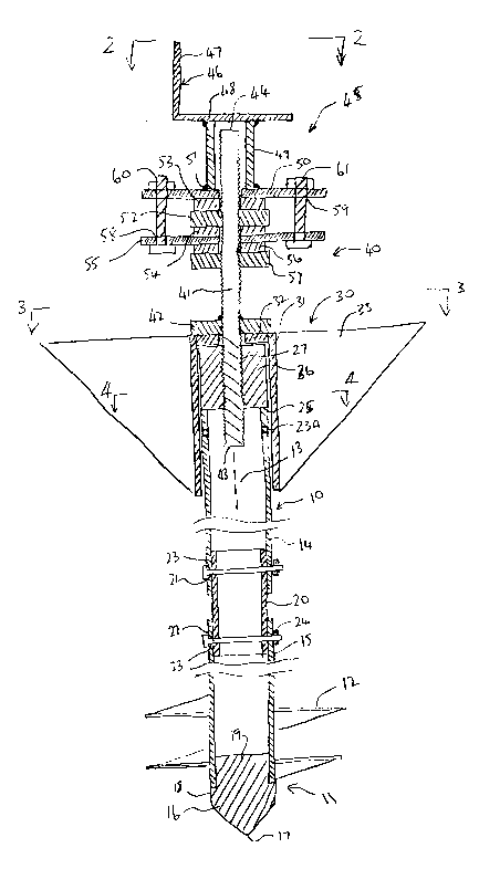
Figure 1 is a vertical cross sectional view through an assembled
ground anchor according to the present invention.
Figure 2 is a end elevational view along the lines 2-2 of Figure 1.

215~4
.
Figure 3 is a cross sectional view along the lines 3-3 of Figure 1.
Figure 4 is a cross sectional view along the lines 4-4 of Figure 1.
Figure 5 is a top plan view of one part only of the ground anchor
of Figure 1 during an installation procedure.
In the drawings like characters of reference indicate corresponding
parts in the different figures.
DETAILED DESCRIPTION
The ground anchor shown in the drawings comprises an elongate
body generally indicated at 10 with a lower end 11 on which is mounted an
auger flight 12. Elongate body has a longitudinal axis 13 with the flight
threaded about that axis so that the flight can be driven into the ground by
rotating the elongate body in engagement with the ground. The elongate body
comprises a pair of tubes 14 and 15 which lie end to end and coaxial relative
to the axis 13. In a preferred embodiment the tubes are of 2 inches outside
diameter. At the lower end 11, the lower tube 15 has an end piece 16
inserted which has a lowermost central apex 17 diverging outwardly to a
shoulder portion 18 of equal diameter to the outside of the tube 15 and an
insert portion 19 engaging into an interior of the tube 15 to hold the end piece16 in place.
The tubes 14 and 15 are interconnected by a cylindrical sleeve 20
which has an outside diameter substantially equal to the inside diameter of the
two tubes so as to be a sliding fit in the adjacent ends of those tubes. A
transverse pin 21, 22 interconnects the cylindrical sleeve to each of the tubes.Thus each tube has a transverse hole 23 formed diametrically there across and
defining an opening in each side of the tube. The pin a preferred arrangement
comprises a 3/4 inch diameter bolt which extends through both of the
openings 23 and carries a nut 24 at its outer end to hold the pin 22 in place.

- 2155~04
The tube 14 extends from the cylindrical sleeve 20 to an upper
end 24 of the tube 25. Adjacent the end 24 is provided a further transverse
pair of holes 23A.
At the upper end 24 is welded a cylindrical nut 26 which is
5 coaxial with the axis 13 and stands upwardly from the top of the tube 14 with
a central threaded bore 27 of the nut extending vertically and coaxially of the
axis 13.
The ground anchor when assembled further includes a stabilizer
assembly 30 comprising a sleeve 31, an end plate 32 at one end of the sleeve
10 and a plurality of wings 33 welded to the outside of the sleeve and extendinggenerally radially outwardly therefrom. In the example shown there are four
such wings each of generally triangular shape but it will be appreciated that
the number of wings can be reduced or increased in accordance with
requirements. A preferred arrangement generally includes three such wings
15 arranged at 120 spacing around the sleeve 31.
Each of the tubes 14 and 15 generally has a length of the order of
4 feet so that the full length of the elongate body 10 is approximately 8 feet.
The flight 12 has a number of turns sufficient so that it's axial length is of the
order of 24 inches which provides a high engagement force relative to the
20 ground after the flight is threaded into the ground thus accommodating
significant axial loads to the elongate body 10.
The ground anchor when assembled further includes a mounting
assembly generally indicated at 40 comprising an elongate threaded rod 41
carrying a nut 42 which is welded to the rod at a predetermined position
25 therealong spaced from a lower end 43 of the rod and an upper end 44 of the
rod. The nut 42 can be rotated to engage the threaded rod into the threaded
bore 27 so that rotation of the nut drives the threaded rod into the nut 26
until a lower end of the threaded rod engages into the interior of the tube 14.

- 2155S04
When the nut 42 engages the plate 32 of the stabilizer assembly, the nut 42
drives the upper plate 32 downwardly thus driving the stabilizer assembly into
the ground until the upper plate 32 engages the top of the nut 26.
The mounting assembly 40 further includes a mounting bracket
assembly 45 including a mounting bracket 46 of L-shape having an upwardly
extending flange 47 and a horizontal base plate 48. On the underside of the
base plate 48 is welded a vertical sleeve 49 of square cross section. The
lower end of the sleeve is welded to a mounting plate 50 which has a central
hole 51 for receiving the threaded rod extending therethrough into the sleeve
49. A nut 52 is threaded onto the threaded rod and abuts against the washer
53 in turn pressing against the mounting plate 50. On the underside of the nut
52 is provided a further washer 54 spacing the nut 52 from a support plate
55. On the underside of the support plate 55 is provided a further washer 56
and a further nut 57. As shown in Figure 2, the base plate 48 is substantially
square and the mounting plate 50 is rectangular so that ends of the support
plate project outwardly beyond ends of the base plate 48. The support plate
55 is coextensive with the mounting plate 50 and each of the plates 50 and 55
is drilled with aligned openings 58 and 59 for receiving bolts 60 and 61. It will
be noted therefore that the weight from the mounting bracket rests upon the
nuts 52 and 57 and is transmitted through the plates 50 and 55. In addition
upward movement of the mounting bracket is prevented by the clamping of
the plate 55 between the nuts 52 and 57 and by interconnection of the
support plate 55 with the mounting plate 50 by way of the bolts 60 and 61.
In addition the height of the mounting bracket can be adjusted by
rotating the nuts 52 and 57 on the threaded rod thus adjusting the height of
the whole mounting assembly relative to the threaded rod. This adjustment
increases and decreases the length of the threaded rod within the sleeve 49.

-- 2155~04
In mounting of the ground anchor into the ground, the elongate
body 10 is initially supplied in the two separate pieces defined by the tubes 14and 15. With the cylindrical coupling sleeve 20 removed, a handle 66 is
engaged with the upper part of the tube 15 by insertion of a pin 67 through
5 the opening 23 transversely of the tube 15 of the upper part of the tube. The
handle includes an elongate handle portion 68 extending from an end of the
pin 67 coaxially therewith with a length of the handle sufficient to allow
manual force in a direction of an arrow 70 to rotate the tube 15 and thus drive
the flight 12 into the ground.
When the tube 15 is driven substantially wholly into the ground,
the handle 66 is removed and the tube 14 attached to the top of the tube 15.
The handle is then inserted through the opening 23A at the top of the tube 14
and the driving rotation of the elongate body continued until the elongate body
is driven into the ground substantially to the top of the elongate body. At this15 time the stabilizer assembly is engaged over the top of the elongate body andthe threaded rod engaged into the nut 26. The threaded rod is then rotated to
the drive the stabilizer assembly downwardly to engage the stabilizer assembly
into the ground. With the threaded rod thus fully engaged into the nut 26, the
threaded rod is supported on the elongate body vertically upwardly therefrom
20 for receiving the mounting assembly as previously described.
Since various modifications can be made in my invention as herein
above described, and many apparently widely different embodiments of same
made within the spirit and scope of the claims without departing from such
spirit and scope, it is intended that all matter contained in the accompanying
25 specification shall be interpreted as illustrative only and not in a limiting sense.

Representative Drawing
A single figure which represents the drawing illustrating the invention.
Administrative Status

2024-08-01:As part of the Next Generation Patents (NGP) transition, the Canadian Patents Database (CPD) now contains a more detailed Event History, which replicates the Event Log of our new back-office solution.

Please note that "Inactive:" events refers to events no longer in use in our new back-office solution.

For a clearer understanding of the status of the application/patent presented on this page, the site Disclaimer , as well as the definitions for Patent , Event History , Maintenance Fee  and Payment History  should be consulted.

Event History

Description Date
Application Not Reinstated by Deadline 1999-08-04
Time Limit for Reversal Expired 1999-08-04
Deemed Abandoned - Failure to Respond to Maintenance Fee Notice 1998-08-04
Inactive: Delete abandonment 1997-10-02
Letter Sent 1997-08-28
Deemed Abandoned - Failure to Respond to Maintenance Fee Notice 1997-08-26
Reinstatement Requirements Deemed Compliant for All Abandonment Reasons 1997-08-12
Deemed Abandoned - Failure to Respond to Maintenance Fee Notice 1997-08-04
Application Published (Open to Public Inspection) 1997-02-05

Abandonment History

Abandonment Date Reason Reinstatement Date
1998-08-04
1997-08-26
1997-08-04

Maintenance Fee

The last payment was received on 1997-08-12

Note : If the full payment has not been received on or before the date indicated, a further fee may be required which may be one of the following

  • the reinstatement fee;
  • the late payment fee; or
  • additional fee to reverse deemed expiry.

Please refer to the CIPO Patent Fees web page to see all current fee amounts.

Fee History

Fee Type Anniversary Year Due Date Paid Date
MF (application, 2nd anniv.) - small 02 1997-08-04 1997-08-12
Reinstatement 1997-08-12
Owners on Record

Note: Records showing the ownership history in alphabetical order.

Current Owners on Record
JAMES MAXWELL WILSON
Past Owners on Record
None
Past Owners that do not appear in the "Owners on Record" listing will appear in other documentation within the application.
Documents

To view selected files, please enter reCAPTCHA code :


To view images, click a link in the Document Description column. To download the documents, select one or more checkboxes in the first column and then click the "Download Selected in PDF format (Zip Archive)" or the "Download Selected as Single PDF" button.

List of published and non-published patent-specific documents on the CPD .

If you have any difficulty accessing content, you can call the Client Service Centre at 1-866-997-1936 or send them an e-mail at CIPO Client Service Centre.


Document
Description 
Date
(yyyy-mm-dd) 
Number of pages   Size of Image (KB) 
Claims 1997-02-05 4 155
Cover Page 1996-10-24 1 15
Abstract 1996-10-24 1 26
Description 1996-10-24 5 212
Drawings 1996-10-24 4 155
Drawings 1996-10-24 3 54
Representative drawing 1997-10-21 1 26
Courtesy - Abandonment Letter (Maintenance Fee) 1997-08-26 1 188
Notice of Reinstatement 1997-08-28 1 172
Courtesy - Abandonment Letter (Maintenance Fee) 1998-09-01 1 189
Fees 1997-08-12 1 40