Sélection de la langue

Search

Sommaire du brevet 2155504 

Énoncé de désistement de responsabilité concernant l'information provenant de tiers

Une partie des informations de ce site Web a été fournie par des sources externes. Le gouvernement du Canada n'assume aucune responsabilité concernant la précision, l'actualité ou la fiabilité des informations fournies par les sources externes. Les utilisateurs qui désirent employer cette information devraient consulter directement la source des informations. Le contenu fourni par les sources externes n'est pas assujetti aux exigences sur les langues officielles, la protection des renseignements personnels et l'accessibilité.

Disponibilité de l'Abrégé et des Revendications

L'apparition de différences dans le texte et l'image des Revendications et de l'Abrégé dépend du moment auquel le document est publié. Les textes des Revendications et de l'Abrégé sont affichés :

  • lorsque la demande peut être examinée par le public;
  • lorsque le brevet est émis (délivrance).
(12) Demande de brevet: (11) CA 2155504
(54) Titre français: DISPOSITIF D'ANCRAGE AU SOL
(54) Titre anglais: GROUND ANCHOR
Statut: Réputée abandonnée et au-delà du délai pour le rétablissement - en attente de la réponse à l’avis de communication rejetée
Données bibliographiques
Abrégés

Abrégé anglais


A ground anchor comprises an elongate body with a flight at a
lower end of the body. The flight is a length of 24 inches and the elongate
body a length of the order of 8 feet and is formed by two tubes arranged end
to end coupled by a cylindrical sleeve pinned to the adjacent ends of the tubes.A winged stabilizer assembly includes a sleeve over an upper end of the
tubular body. The stabilizer assembly is clamped downwardly into the ground
by a nut welded to a threaded rod which engages into a second nut welded to
the top of the tube. The threaded rod is thus supported vertically upwardly
from the top of the tube and supports a mounting assembly. The mounting
assembly comprises a bracket having a base plate and a mounting plate
parallel to the base plate with a sleeve therebetween for receiving the upper
end of the threaded rod. A nut carries the mounting plate adjustably on the
threaded rod. A support plate parallel to the mounting plate is carried on a
second nut on the threaded rod. The mounting plate and the support plate are
clamped together by a pair of bolts parallel to the threaded rod.

Revendications

Note : Les revendications sont présentées dans la langue officielle dans laquelle elles ont été soumises.


CLAIMS
1. A ground anchor for engagement into the ground
comprising an elongate body having a longitudinal axis, a flight attached to thebody around the axis adjacent a lower end thereof, engagement means on the
body for engaging a handle for drivingly rotating the body about the axis for
threading the flight into the ground, and mounting means as an upper end of
the body for engaging a member to be supported relative to the ground, the
elongate body comprising a tube.
2. The ground anchor according to Claim 1 wherein the
elongate body comprises two separate tubes coupled end to end.
3. The ground anchor according to Claim 2 wherein the two
separate tubes are coupled by a cylindrical body projecting into the adjacent
ends of the tubes and a pair of transverse pins each coupling the cylindrical
body to a respective one of the tubes.
4. The ground anchor according to Claim 1 wherein the
mounting means comprises a nut welded to the upper end of the body and
defining a vertical threaded bore and a threaded rod for engagement into the
bore.
5. The ground anchor according to Claim 4 wherein the
threaded rod extends through the nut into the upper end of the tube.
6. The ground anchor according to Claim 4 wherein the
threaded rod has a nut welded thereto at a position partly along the length of
the threaded rod such that rotation of the nut threads the threaded rod into thenut on the end of the body.
7. The ground anchor according to Claim 6 including a
stabilizer assembly having a sleeve for surrounding the upper end of the body
and a plurality of wings extending outwardly from the sleeve generally radially
to the axis, the sleeve having a top plate for surrounding a threaded rod and

7
for engaging the nut welded to the threaded rod for driving the stabilizer
assembly downwardly onto the top of the elongate body.
8. The ground anchor according to Claim 4 wherein the
mounting means further includes a mounting a bracket for attachment to the
member having a base plate, a sleeve attached to an underside of the base
plate and extending downwardly therefrom and a support plate parallel to the
base plate, the threaded rod extending into the sleeve, and a nut engaged on
the threaded rod for supporting the mounting plate, the height of the mounting
plate and the bracket on the threaded rod being adjustable by the nut so that
the length of the threaded rod extending into the sleeve varies in dependence
upon the position of the nut on the threaded rod.
9. The ground anchor according to Claim 8 wherein the
mounting means further includes a second plate parallel to the first mounting
plate, a second nut supporting a second plate and at least two nut and bolt
fasteners spaced radially outwardly from the threaded rod and interconnecting
the second plate and the mounting plate.
10. The ground anchor according to Claim 1 wherein the
engagement means comprises a transverse hole through the body for engaging
a horizontal pin.
11. The ground anchor according to Claim 10 wherein the
handle comprises a horizontal pin and an elongate member coaxial with the pin
and extending longitudinally therefrom.
12. The ground anchor according to Claim 1 wherein the flight
has an axial length of the order of 24 inches.
13. A ground anchor for engagement into the ground
comprising an elongate body having a longitudinal axis, a flight attached to thebody around the axis adjacent a lower end thereof, engagement means on the
body for engaging a handle for drivingly rotating the body about the axis for

threading the flight into the ground, and mounting means as an upper end of
the body for engaging a member to be supported relative to the ground,
wherein the mounting means comprises a nut welded to the upper end of the
body and defining a vertical threaded bore and a threaded rod for engagement
into the bore.
14. The ground anchor according to Claim 13 wherein the
mounting means comprises a nut welded to the upper end of the body and
defining a vertical threaded bore and a threaded rod for engagement into the
bore.
15. The ground anchor according to Claim 14 wherein the body
comprises a tube and wherein the threaded rod extends through the nut into
the upper end of the tube.
16. The ground anchor according to Claim 14 wherein the
threaded rod has a nut welded thereto at a position partly along the length of
the threaded rod such that rotation of the nut threads the threaded rod into thenut on the end of the body.
17. The ground anchor according to Claim 16 including a
stabilizer assembly having a sleeve for surrounding the upper end of the body
and a plurality of wings extending outwardly from the sleeve generally radially
to the axis, the sleeve having a top plate for surrounding a threaded rod and
for engaging the nut welded to the threaded rod for driving the stabilizer
assembly downwardly onto the top of the elongate body.
18. A ground anchor for engagement into the ground
comprising an elongate body having a longitudinal axis, a flight attached to thebody around the axis adjacent a lower end thereof, engagement means on the
body for engaging a handle for drivingly rotating the body about the axis for
threading the flight into the ground, and mounting means as an upper end of
the body for engaging a member to be supported relative to the ground,

wherein the mounting means further includes a mounting bracket for
attachment to the member having a base plate, a sleeve attached to an
underside of the base plate and extending downwardly therefrom and a
support plate parallel to the base plate, the threaded rod extending into the
sleeve, and a nut engaged on the threaded rod for supporting the mounting
plate, the height of the mounting plate and the bracket on the threaded rod
being adjustable by the nut so that the length of the threaded rod extending
into the sleeve varies in dependence upon the position of the nut on the
threaded rod.
19. The ground anchor according to Claim 18 wherein the
mounting means further includes a second plate parallel to the first mounting
plate, a second nut supporting a second plate and at least two nut and bolt
fasteners spaced radially outwardly from the threaded rod and interconnecting
the second plate and the mounting plate.
20. The ground anchor according to Claim 18 wherein the
engagement means comprises a transverse hole through the body for engaging
a horizontal pin.
21. The ground anchor according to Claim 20 wherein the
handle comprises a horizontal pin and an elongate member coaxial with the pin
and extending longitudinally therefrom.
22. The ground anchor according to Claim 18 wherein the flight
has an axial length of the order of 24 inches.

Description

Note : Les descriptions sont présentées dans la langue officielle dans laquelle elles ont été soumises.

~ 21~`550~
GROUND ANCHOR
BACKGROUND OF THE INVENTION
This invention relates to a ground anchor of the type comprising
an elongate body defining a longitudinal axis, a flight attached to the body
5 around the axis adjacent a lower end of the body, engagement means on the
body for engaging a handle for drivingly rotating the body about the axis for
threading the flight into the ground and mounting means at an upper end of
the body for engaging a member to be supported relative to the ground.
An example of a ground anchor of this type is shown in prior
10 Canadian Patent 1,297,259 of the present inventor.
SUMMARY OF THE INVENTION
It is one object of the present invention to provide an improved
arrangement of the ground anchor defined above which may enable reductions
in costs of the manufactured elements.
According to the first aspect of the invention there is provided a
ground anchor for engagement into the ground comprising an elongate body
having a longitudinal axis, a flight attached to the body around the axis
adjacent a lower end thereof, engagement means on the body for engaging a
handle for drivingly rotating the body about the axis for threading the flight
20 into the ground, and mounting means as an upper end of the body for
engaging a member to be supported relative to the ground, the elongate body
comprising a tube
One embodiment of the invention will now be described in
conjunction with the accompanying drawings in which:
25 BRIEF DESCRIPTION OF THE DRAWINGS
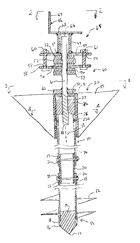
Figure 1 is a vertical cross sectional view through an assembled
ground anchor according to the present invention.
Figure 2 is a end elevational view along the lines 2-2 of Figure 1.

215~4
.
Figure 3 is a cross sectional view along the lines 3-3 of Figure 1.
Figure 4 is a cross sectional view along the lines 4-4 of Figure 1.
Figure 5 is a top plan view of one part only of the ground anchor
of Figure 1 during an installation procedure.
In the drawings like characters of reference indicate corresponding
parts in the different figures.
DETAILED DESCRIPTION
The ground anchor shown in the drawings comprises an elongate
body generally indicated at 10 with a lower end 11 on which is mounted an
auger flight 12. Elongate body has a longitudinal axis 13 with the flight
threaded about that axis so that the flight can be driven into the ground by
rotating the elongate body in engagement with the ground. The elongate body
comprises a pair of tubes 14 and 15 which lie end to end and coaxial relative
to the axis 13. In a preferred embodiment the tubes are of 2 inches outside
diameter. At the lower end 11, the lower tube 15 has an end piece 16
inserted which has a lowermost central apex 17 diverging outwardly to a
shoulder portion 18 of equal diameter to the outside of the tube 15 and an
insert portion 19 engaging into an interior of the tube 15 to hold the end piece16 in place.
The tubes 14 and 15 are interconnected by a cylindrical sleeve 20
which has an outside diameter substantially equal to the inside diameter of the
two tubes so as to be a sliding fit in the adjacent ends of those tubes. A
transverse pin 21, 22 interconnects the cylindrical sleeve to each of the tubes.Thus each tube has a transverse hole 23 formed diametrically there across and
defining an opening in each side of the tube. The pin a preferred arrangement
comprises a 3/4 inch diameter bolt which extends through both of the
openings 23 and carries a nut 24 at its outer end to hold the pin 22 in place.

- 2155~04
The tube 14 extends from the cylindrical sleeve 20 to an upper
end 24 of the tube 25. Adjacent the end 24 is provided a further transverse
pair of holes 23A.
At the upper end 24 is welded a cylindrical nut 26 which is
5 coaxial with the axis 13 and stands upwardly from the top of the tube 14 with
a central threaded bore 27 of the nut extending vertically and coaxially of the
axis 13.
The ground anchor when assembled further includes a stabilizer
assembly 30 comprising a sleeve 31, an end plate 32 at one end of the sleeve
10 and a plurality of wings 33 welded to the outside of the sleeve and extendinggenerally radially outwardly therefrom. In the example shown there are four
such wings each of generally triangular shape but it will be appreciated that
the number of wings can be reduced or increased in accordance with
requirements. A preferred arrangement generally includes three such wings
15 arranged at 120 spacing around the sleeve 31.
Each of the tubes 14 and 15 generally has a length of the order of
4 feet so that the full length of the elongate body 10 is approximately 8 feet.
The flight 12 has a number of turns sufficient so that it's axial length is of the
order of 24 inches which provides a high engagement force relative to the
20 ground after the flight is threaded into the ground thus accommodating
significant axial loads to the elongate body 10.
The ground anchor when assembled further includes a mounting
assembly generally indicated at 40 comprising an elongate threaded rod 41
carrying a nut 42 which is welded to the rod at a predetermined position
25 therealong spaced from a lower end 43 of the rod and an upper end 44 of the
rod. The nut 42 can be rotated to engage the threaded rod into the threaded
bore 27 so that rotation of the nut drives the threaded rod into the nut 26
until a lower end of the threaded rod engages into the interior of the tube 14.

- 2155S04
When the nut 42 engages the plate 32 of the stabilizer assembly, the nut 42
drives the upper plate 32 downwardly thus driving the stabilizer assembly into
the ground until the upper plate 32 engages the top of the nut 26.
The mounting assembly 40 further includes a mounting bracket
assembly 45 including a mounting bracket 46 of L-shape having an upwardly
extending flange 47 and a horizontal base plate 48. On the underside of the
base plate 48 is welded a vertical sleeve 49 of square cross section. The
lower end of the sleeve is welded to a mounting plate 50 which has a central
hole 51 for receiving the threaded rod extending therethrough into the sleeve
49. A nut 52 is threaded onto the threaded rod and abuts against the washer
53 in turn pressing against the mounting plate 50. On the underside of the nut
52 is provided a further washer 54 spacing the nut 52 from a support plate
55. On the underside of the support plate 55 is provided a further washer 56
and a further nut 57. As shown in Figure 2, the base plate 48 is substantially
square and the mounting plate 50 is rectangular so that ends of the support
plate project outwardly beyond ends of the base plate 48. The support plate
55 is coextensive with the mounting plate 50 and each of the plates 50 and 55
is drilled with aligned openings 58 and 59 for receiving bolts 60 and 61. It will
be noted therefore that the weight from the mounting bracket rests upon the
nuts 52 and 57 and is transmitted through the plates 50 and 55. In addition
upward movement of the mounting bracket is prevented by the clamping of
the plate 55 between the nuts 52 and 57 and by interconnection of the
support plate 55 with the mounting plate 50 by way of the bolts 60 and 61.
In addition the height of the mounting bracket can be adjusted by
rotating the nuts 52 and 57 on the threaded rod thus adjusting the height of
the whole mounting assembly relative to the threaded rod. This adjustment
increases and decreases the length of the threaded rod within the sleeve 49.

-- 2155~04
In mounting of the ground anchor into the ground, the elongate
body 10 is initially supplied in the two separate pieces defined by the tubes 14and 15. With the cylindrical coupling sleeve 20 removed, a handle 66 is
engaged with the upper part of the tube 15 by insertion of a pin 67 through
5 the opening 23 transversely of the tube 15 of the upper part of the tube. The
handle includes an elongate handle portion 68 extending from an end of the
pin 67 coaxially therewith with a length of the handle sufficient to allow
manual force in a direction of an arrow 70 to rotate the tube 15 and thus drive
the flight 12 into the ground.
When the tube 15 is driven substantially wholly into the ground,
the handle 66 is removed and the tube 14 attached to the top of the tube 15.
The handle is then inserted through the opening 23A at the top of the tube 14
and the driving rotation of the elongate body continued until the elongate body
is driven into the ground substantially to the top of the elongate body. At this15 time the stabilizer assembly is engaged over the top of the elongate body andthe threaded rod engaged into the nut 26. The threaded rod is then rotated to
the drive the stabilizer assembly downwardly to engage the stabilizer assembly
into the ground. With the threaded rod thus fully engaged into the nut 26, the
threaded rod is supported on the elongate body vertically upwardly therefrom
20 for receiving the mounting assembly as previously described.
Since various modifications can be made in my invention as herein
above described, and many apparently widely different embodiments of same
made within the spirit and scope of the claims without departing from such
spirit and scope, it is intended that all matter contained in the accompanying
25 specification shall be interpreted as illustrative only and not in a limiting sense.

Dessin représentatif
Une figure unique qui représente un dessin illustrant l'invention.
États administratifs

2024-08-01 : Dans le cadre de la transition vers les Brevets de nouvelle génération (BNG), la base de données sur les brevets canadiens (BDBC) contient désormais un Historique d'événement plus détaillé, qui reproduit le Journal des événements de notre nouvelle solution interne.

Veuillez noter que les événements débutant par « Inactive : » se réfèrent à des événements qui ne sont plus utilisés dans notre nouvelle solution interne.

Pour une meilleure compréhension de l'état de la demande ou brevet qui figure sur cette page, la rubrique Mise en garde , et les descriptions de Brevet , Historique d'événement , Taxes périodiques et Historique des paiements devraient être consultées.

Historique d'événement

Description Date
Demande non rétablie avant l'échéance 1999-08-04
Le délai pour l'annulation est expiré 1999-08-04
Réputée abandonnée - omission de répondre à un avis sur les taxes pour le maintien en état 1998-08-04
Inactive : Supprimer l'abandon 1997-10-02
Lettre envoyée 1997-08-28
Réputée abandonnée - omission de répondre à un avis sur les taxes pour le maintien en état 1997-08-26
Exigences de rétablissement - réputé conforme pour tous les motifs d'abandon 1997-08-12
Réputée abandonnée - omission de répondre à un avis sur les taxes pour le maintien en état 1997-08-04
Demande publiée (accessible au public) 1997-02-05

Historique d'abandonnement

Date d'abandonnement Raison Date de rétablissement
1998-08-04
1997-08-26
1997-08-04

Taxes périodiques

Le dernier paiement a été reçu le 1997-08-12

Avis : Si le paiement en totalité n'a pas été reçu au plus tard à la date indiquée, une taxe supplémentaire peut être imposée, soit une des taxes suivantes :

  • taxe de rétablissement ;
  • taxe pour paiement en souffrance ; ou
  • taxe additionnelle pour le renversement d'une péremption réputée.

Veuillez vous référer à la page web des taxes sur les brevets de l'OPIC pour voir tous les montants actuels des taxes.

Historique des taxes

Type de taxes Anniversaire Échéance Date payée
TM (demande, 2e anniv.) - petite 02 1997-08-04 1997-08-12
Rétablissement 1997-08-12
Titulaires au dossier

Les titulaires actuels et antérieures au dossier sont affichés en ordre alphabétique.

Titulaires actuels au dossier
JAMES MAXWELL WILSON
Titulaires antérieures au dossier
S.O.
Les propriétaires antérieurs qui ne figurent pas dans la liste des « Propriétaires au dossier » apparaîtront dans d'autres documents au dossier.
Documents

Pour visionner les fichiers sélectionnés, entrer le code reCAPTCHA :


Pour visualiser une image, cliquer sur un lien dans la colonne description du document. Pour télécharger l'image (les images), cliquer l'une ou plusieurs cases à cocher dans la première colonne et ensuite cliquer sur le bouton "Télécharger sélection en format PDF (archive Zip)" ou le bouton "Télécharger sélection (en un fichier PDF fusionné)".

Liste des documents de brevet publiés et non publiés sur la BDBC .

Si vous avez des difficultés à accéder au contenu, veuillez communiquer avec le Centre de services à la clientèle au 1-866-997-1936, ou envoyer un courriel au Centre de service à la clientèle de l'OPIC.


Description du
Document 
Date
(aaaa-mm-jj) 
Nombre de pages   Taille de l'image (Ko) 
Revendications 1997-02-05 4 155
Page couverture 1996-10-24 1 15
Abrégé 1996-10-24 1 26
Description 1996-10-24 5 212
Dessins 1996-10-24 4 155
Dessins 1996-10-24 3 54
Dessin représentatif 1997-10-21 1 26
Courtoisie - Lettre d'abandon (taxe de maintien en état) 1997-08-26 1 188
Avis de retablissement 1997-08-28 1 172
Courtoisie - Lettre d'abandon (taxe de maintien en état) 1998-09-01 1 189
Taxes 1997-08-12 1 40