Note: Descriptions are shown in the official language in which they were submitted.
~ Wo95/17236 ~ ~ ~ S S ~ 3 2 pcTruss4ll48l9
FILTRATION MEDIA AND DEVICE FOR FILTERING LEUKOCYTES
Field of th~ Inv~ntion:
The invention generally relates to blood
collection and processing systems and methods. In
a more particular sense, the invention relates to
systems and methods for removing leukocytes from red
blood cells before transfusion or long term storage.
B~ck~o~d of the Invention:
Most of the whole blood collected from do-
nors today is not itself stored and used for
transfusion. Instead, the whole blood is separated
into its clinically proven components (typically red
blood cells, platelets, and plasma), which are them-
selves individually stored and used to treat a
multiplicity of specific conditions and diseased
states. For example, the red blood cell component
is used to treat anemia; the concentrated platelet
component is used to control thrombocytopenic
bleeding; and the platelet-poor plasma component is
used as a volume expander or as a source of Clotting
Factor VIII for the treatment of hemophilia.
Plastic bags have met widespread use and
acceptance for collecting, processing and storing
these blood components.
In collecting whole blood components for
transfusion, it is desirable to minimize the
presence of impurities or other materials that may
cause undesired side effects in the recipient. For
example, because of possible febrile reactions, it
is generally considered desirable to transfuse red
blood cells substantially free of leukocytes,
WO95/17236 ~ lS~ ~ 3 2 PCT~S94/14819
particularly for recipients who undergo frequent
transfusions.
One way to remove leukocytes is by washing
the red blood cells with saline. This techn;que is
time consuming and inefficient,~-~às it can reduce the
number of red blood cells available for transfusion.
Another way to remove leukocytes is by
filtration. Systems and methods for accomplishing
this in conventional blood bag systems are described
in Wisdom U.S. Patents 4,596,657 and 4,767,541, as
well as in Carmen et al U.S. Patents 4,810,378 and
4,855,063. Other systems and methods for removing
leukocytes in the blood bag systems are described in
Stewart U.S. Patent 4,997,577 and Stewart et al.
U.S. Patent 5,128,048. In these arrangements, an in
line filtration device is used.
A need still exists for further improved
systems and methods for removing undesired matter
like leukocytes from blood components before
transfusion or storage.
8ummarY of the Invention:
The invention provides a filtration media
for removing leukocytes from a blood suspension.
The media comprises non-contiguous layers having an
overall thickness of greater than about 6 mm but not
more than about l0 mm. Each non-contiguous layer
comprises an interlocked matrix of polyester fibers,
fiberglass fibers, and cellulose acetate fibrets.
The matrix has a number average fiber diameter no
greater than about 0.23 micron.
According to this aspect of the invention,
the number average diameter is calculated as
follows:
(i) deriving the length of each fiber
material present in the matrix, using the following
WO95/17236 ~ 7 3 2 PCT~S94/14819
equation:
L~ , 4Qi
~ p ~d2
where:
$ is the selected fiber (polyester,
fiberglass, and cellulose acetate fibrets);
Li is the length of the selected fiber
(in cm);
Q$ is the weight fraction of the
selected fiber (expressed as a decimal; e.g., 10% =
0.1);
~ is 3.1417;
di is the diameter of the selected
fiber (in cm); and
Pi is the density of the selected
fiber (in g/cm3); and
where:
the diameter of the cellulose acetate
fibrets (which presents a complex fiber structure
that cannot be readily measured by conventional
means) is derived according to the following
equation:
d = 4 x A/W
where:
d is the diameter of the cellulose
acetate fibrets (in cm, or, by multiplying cm by
10,000, in microns);
p is the density of the cellulose
acetate from which the fibrets are formed (in
g/cm3); and
A/W is the area-to-weight ratio of the
cellulose acetate fibrets (in cm2/g); and
W095/17236 PCT~S94/14819 ~
2~5~t3~ _
- 4
(ii) deriving the number average diameter
of all fibers present in the matrix by adding
together the product of the length Li (expressed in
cm) and diameter divided by the length Li (in cm/g)
for each fiber, using the following equation:
~Lf X di
2~Lf
where:
i is the fiber;
Li is the length of the fiber (in cm);
di is the diameter of the fiber (in
cm).
It has been determined that ~he number
average fiber diameter, as calculated above, can be
used to correlated various physical and performance
characteristics of the complex leukodepletion media.
A number average fiber diameter of no more than
about 0.23 micron, as calculated above, correlates
with an acceptable log reduction of leukocytes in
whole blood at an acceptable whole blood flow rate.
other features and advantages of the inven-
tion will become apparent upon review of thefollowing description, drawings, and appended
claims.
Brief De~cription of the Drawing~:
Fig. l is a schematic view of a blood col-
lection assembly that embodies the features of theinvention;
Fig. 2 is an exploded perspective view of
the filter device that is associated with the
assembly shown in Fig. l, showing the filter pad
assembly and surroundi~g housing;
Fig. 3 is an exploded side section view of
~ W095/17236 2 1 ~ 5 7 3 2 PCT~S94J14819
the first, second, and third media regions of the
filter pad assembly shown in Fig. 2;
Fig. 4 is a side section view of the
formation of the peripheral seal about the first,
second, and third media regions to create the filter
pad assembly using an ultrasonic sealing tool;
Fig. 5 is a side view of the composite
filter pad assembly that is formed in Fig. 4;
Fig. 6 is an exploded perspective view of
the assembly of the filter housing to the composite
filter pad assembly using a radiofrequency welding
tool;
Fig. 7 is a perspective view of the filter
device that is formed in Fig. 6;
Fig. 8 is a fragmentary cross-sectional
view taken centrally through a port in the wall of
the filter device of Fig. 7;
Fig. 9 is a frag~entary view of sheet of
material showing an initial step in the manufacture
of the port shown in Fig. 8;
Fig. 10 is a fragmentary view showing a
further step in the manufacturing of the port shown
in Fig. 8;
Fig. 11 is a fragmentary view showing the
finished port in the filter device;
Fig. 12 is a central sectional view showing
the components in the manufacture of the port prior
to heating thereof;
Fig. 13 is a sectional view of the
components shown in Fig. 12 during the heating step;
Fig. 14 is a sectional view taken along
line 14-14 of Fig. 13;
Fig. 15 is a table, calculated according to
one aspect of the invention, showing the number
average fiber diameters for complex filtration media
W095/17236 2 ~ 3 æ ~ PCT~S94/14819
comprising given weight percentages of polyester
fiber/core sheath; fiberglass fiber; and cellulose
acetate fibrets;
Fig. 16 charts the nu~mber average fiber
diameter of the complex media~(-x-axis) against mean
flow pore size (y-axis) of-~he media based upon
empirical data, showing a trend that correlates
these two structural characteristics;
Fig. 17 charts the number average fiber
diameter of the media (x-axis) against the flow time
of whole blood (y-axis) through the media, based
upon empirical data, showing a trend that correlates
the structural characteristic (fiber diameter) with
an expected performance characteristic (flow time);
and
Fig. 18 charts the mean flow pore size (x-
axis) of the media against the log depletion of
leukocytes in whole blood (y-axis) passed through
the media, based upon empirical data, showing a
trend that correlates the physical characteristic
(mean flow pore size) with an expected performance
characteristic (le~kocyte depletion).
The invention may be embodied in several
forms without departing from its spirit or essential
characteristics. The scope of the invention is
defined in the appended claims, rather than in the
specific description preceding them. All em-
bodiments that fall within the meaning and range of
equivalency of the claims are therefore intended to
be embraced by the claims.
Description of the Preferred Embodiments:
A blood collection assembly lO is shown in
Fig. l. In the illustrated embodiment, the assembly
lO serves to filter leukocytes from red blood cells
before transfusion.
~ WO95/17236 2 1 5 5 7 3 2 PCT~S94/14819
In the embodiment shown in Fig. 1, the
assembly 10 includes a transfer bag or container 12.
The transfer bag 12 includes integrally attached
transfer tubing 14. In the illustrated embodiment,
the tubing 14 carries a conventional blood bag spike
26 at its distal end. As will be discùssed later,
other types of aseptic or sterile connectors can be
used.
The transfer tubin~ 14 also carries an in
line filter device 16. As Figs. 2 and 7 best show,
the filter device 16 includes a two part housing 18
that encapsulates a filter pad assembly 20. The pad
assembly 20 is intended to be used to remove
leukocytes from red blood cells.
The system 10 further includes a vent path
22. The vent path 22 also leads to the transfer bag
12, but it bypasses the filter device 16.
The vent path 22 includes an in line one
way valve 24. The valve 24 allows flow through the
path 22 from the transfer bag 12 toward the spike
26, but blocks flow through the path 22 from the
spike 26 toward the transfer bag 12.
The bag 12 and tubing 14/22 associated with
the as-sembly 10 can be made from conventional ap-
proved medical grade plastic materials, such as
polyvinyl chloride plasticized with di-2-ethylhexyl-
phthalate (DEHP). Conventional "Y" or "T" connec-
tors 28 can be used to form the branched paths
14/22.
In use, the spike 26 is inserted into a
port of a conventional primary blood collection bag
(not shown). The primary bag contains red blood
cells, which have been earlier separated from whole
blood by centrifugation.
The red blood cells flow by gravity from
W095/17236 2 ~5 S ~ 3 ~ PCT~S94/14819
the primary bag into the transfer t~bing 14 and
through the filter device 16. The filter pad
assembly 20 removes leukocytes from the red blood
cells as they pass through the device 16.
The one way valve 2~4~prevents parallel flow
through the vent path 22.
The red blood cells, with all or a portion
of the leukocytes removed, exit the filter device 16
and enter the transfer bag 12.
Once the primary bag connected to the spike
26 empties and flow has stopped, the user clamps the
transfer tubing 14 immediately above and below the
filter device 16. The user then manually squeezes
the transfer bag 12 to express air from it. The air
flows through the vent path 22, bypassing the
filtration device 16, back toward the primary bag
16.
The user then removes the clamps above and
below the filter device 16. The air pressure now
resident in the assembly 10 upstream of the filter
device 16 urges residual red blood cells through the
filter device 16 and into the transfer bag 12.
- The transfer bag 12 can now be detached
from the assembly 10 for storing or transfusing the
leukocyte-depleted red blood cells.
The detachment can be accomplished using a
conventional heat sealing device (for example, the
Hematron~ dielectric sealer sold by Baxter
Healthcare Corporation), which forms a hermetic,
snap-apart seal in the transfer tubing 14 somewhere
downstream of its junction with the vent path 22.
In an alternative arrangement (not shown),
instead of the spike 26, the transfer tubing 14 can
carry a sterile connection device that mates with a
sterile connection device carried by the primary
-
~ WO 95117236 2 1 5 5 7 3 2 rcTlus9~ll48l9
bag. The user brings the mating sterile connection
devices together at time of use. Sterile connection
devices that could be used for this purpose are
shown in Granzow et al. U.S. Patents 4,157,723 and
4,265,280.
Alternatively, the sterile connection can
be accomplished in the manner described in Spencer
U.S. Patent U.S. 4,412,835. In this arrangement, a
seal is formed between a region of the transfer
tubing 14 and a tube carried by the primary bag.
Further details of the filter device 16
will now be discussed.
The Filtration Device
The filter device 16 can be variously
constructed.
In the illustrated and preferred embodiment
(best shown in Figs. 2 and 7), the outer housing 18
enclosing the filter pad assembly 20 comprises two
sheets 44 and 46 of flexible plastic material. The
housing 18 is thus "soft," instead of rigid.
Also in the illustrated and preferred
embodiment, the filter device 16 includes tangential
side ports, one port 36 (in sheet 44) serving as an
inlet and the other port 38 (in sheet 46) serving as
an outlet.
The ports 36 and 38 are arranged about 180
degrees apart on opposite flow sides of the filter
device 16 (see Figs. 1 and 2). This orientation
facilitates the set up and use of the filter device
18 in gravity flow conditions, as Figs. 1 and 7
show.
The tangential, oppositely spaced ports 36
and 38 allow the dir@ct attachment of transfer
tubing 14 without kinking or hr~n~ ing. The
tangential, oppositely spaced ports 36 and 38 also
WO9S/17236 PCT~S94/14819 ~
5~3~ ;
-- 10 --
allow the filter device 16 to hang in a vertical
position during use. This vertical position allows
air trapped in the filter device 16 to vent through
the filter pad assembly 20 during priming,
preventing air entrapment a~d the need for auxiliary
air vents.
Further details of the ports 36 and 38 will
be described later.
The flexible housing 18 avoids the handling
and processing problems rigid filter housings have
presented in the past. Unlike a rigid housing, the
flexible housing 18 will not puncture associated
bags, which are also made of flexible plastic
materials. Unlike a rigid housing, the flexible
housing 18 conforms and is compliant to stress and
pressures induced during use.
The flexible sheet 44 on the inlet side of
the filter device 16 expands under the fluid head
pressure of gravity flow. It thus creates a natural
pressure manifold, which evenly distributes the
fluid across the inlet face of the filter pad
assembly 20. This assures that entrapped air is
vented and that the fluid flows through the filter
pad assembly 20 under uniform pressure and
distribution.
When the distance between the filter device
16 and the source container is at a determinable
amount (approximately 0.75 meter), the fluid head
pressure within the inlet side is sufficient for the
filter device 12 to become self-priming. The user
is not required to "squeeze prime" the filter device
16, by squeezing the source container.
As the fluid container empties, negative
pressure is created downstream of the filter device
16. Because the inlet and outlet sheets 44 and 46
WO95/17236 PCT~S94114819
215~732
of the housing 18 are flexible, they will collapse
around the space occupied by the filter pad assembly
20. Fluid drains from the outlet side without the
use of an auxiliary air vent.
Furthermore, the flexible housing 18 will
not crack during heat sterilization. The flexible
housing 18 also does not impede heat penetration
during heat sterilization processes. Instead, the
housing 18 accommodates uniform heat penetration
into the filter pad assembly 20.
In the illustrated and preferred embodiment
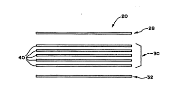
(as Fig. 3 best shows), the filter pad assembly 20
comprises a composite of three media regions
28/30/32.
The first media region 28 serves as a
prefilter. Its purpose is to remove microaggregates
of cellular blood components that can form in red
blood cells after collection.
The second media region 30 serves as a
leukocyte removal filter.
The third media region 32 serves as a
manifold. It keeps the downstream side of the
filter pad assembly 20 open to fluid flow, despite
the presence of a negative fluid head pressure that
pulls the downstream side of the flexible housing 18
(i.e., flexible sheet 46) in against the third media
region 32.
As Figs. 2 and 5 best show, a sealed region
34 joins the three media regions 28/30/32 at their
peripheries. At least one of the media regions
28/30/32 extends above and below the sealed
periphery 34. The region 34 is created by the
application of heat and pressure, as will be
described later.
In the illustrated and preferred embodiment
WO95117236 PCT~S94/14819 ~
~s5~3~
- 12 -
(see Fig. 5), the pad assembly 20 is essentially
symmetrical with respect to the sealed region 34;
that is, the thickness of the filter pad assembly 20
that rises above the sealedireagion 34 is generally
the same as the thickness of the filter pad assembly
20 that extends below the sealed region 34.
The sealed region 34 comprises a rigid,
flat surface. It bonds the peripheries of the media
regions 28/30/32 to each other. This prevents fluid
being filtered from leaking past or bypassing one or
more of the media regions 28/30/32.
As will be described in greater detail
later, the rigid, flat surface the seal region 34
presents also presents a surface to which the
flexible housing 18 can be bonded.
The First Media Re~ion
While the constituents of the first media
region 28 can vary, in the preferred embodiment, the
first media region 28 comprises a needled assembly
of three non-woven polyester fiber mats. The region
28 has an overall thickness of about 2 millimeters.
In the preferred embodiment, the fibers
differ in denier among the three mat layers. The
first mat layer comprises 1.0 denier polyester fiber
(available from Hoescht Corporation, as L30 Fiber).
The second mat layer comprises 1.5 denier polyester
fiber (available Hoescht Corporation, as 224 Fiber).
The third mat layer comprises 3.0 denier polyester
fiber (also available as Hoescht 224 Fiber).
Components for the needled assembly can be
purchased from Hoescht Corporation.
The Second Media Reqion
In the preferred embodiment (see Fig. 3),
the second media region 30 comprises five individual
layers 40 of a non-woven fiber media stacked one
3 2 pcT~s94ll48ls
WO95/17236
- 13 -
above the other.
In the preferred embodiment, each layer 40
of the second media region 30 has the same
composition. Each layer 40 comprises web of
interlocked polyester fibers, fiberglass fibers, and
cellulose acetate fibrets made in accordance with
the teaching of Heagle et al. U.S. Patent 5,190,657,
which is incorporated into this Specification by
reference.
While the thiçkness of each individual
layer 40 can vary, in the illustrated embodiment,
each individual layer 40 has a nominal thickness of
about 2 millimeters. The composite thickness of the
5 layer second media region 30 is therefore about lO
millimeters.
The precise composition and mix of the
fiber components within each layer 40 can vary. In
the preferred embodiment, the mix of interlocked
fibers in each layer 40 constitutes about 75% by
weight of 0.5 denier polyester fiber (made by Teijin
Corporation, Type TK04N); about 10% by weight of
microglass fiber (made by Schuller Corporation, Type
Code 106); and about 5% by weight of cellulose
acetate fibrets (made by Hoechst Corporation).
The interlocked fibers in each layer 40 are
supported on a core sheath structure of polyolefin
fibers that constitutes about lO percent by weight
of the layer (made by Chisso Corporation, Type EKC).
To reduce the incidence of particle
shedding, each layer 40 is preferably coated after
assembly by spraying with an acrylic emulsion. The
acrylic emulsion coating serves to significantly
reduce the incidence of particle shedding within the
pad assembly 20.
It has been observed empirically the
_ _ _
WO9S/17236 PCT~S94/14819 ~
3~
emulsion that is sprayed on the layer 40 should not
constitute more than about 0.3% acrylic by volume.
The use of an emulsion that is greater than 0.3%
acrylic by volume has been observed to degrade the
leukocyte depletion capabilities of the layer 40.
It is believed that the degradation occurs because
the thickness of the coating applied to the fibers
begins to constrict the tortuous fluid paths through
the layer 40.
An acrylic volume of 0.3% or less in the
emulsion maximizes the intended anti-shedding effect
without compromising the leukocyte depletion
capabilities of the layer 40.
In the preferred embodiment, a 0.25%
percent acrylic emulsion made by Rohm and Haas (Type
HA8) is used. Each layer 40 so coated meets the
AAMI particle shedding requirements for filtration
devices.
It has also been determined t:hat, to
maximize the Ieukocyte removal efficiency of the
second media region 30, a composite thickness for
the second region 30 should exceed about 6 mm but
should not exceed about lO mm. Preferably,
multiple layers should be used to obtain this
composite nominal thicknesses.
A significant increase in leukocyte removal
is observed when four individual layers of 2mm
nominal thickness each are used, as compared to
three individual 2 mm layers. Still further
increases are observed when a fifth 2mm layer is
added.
The further addition of individual layers
beyond five (exceeding a total composite nominal
thickness about lO mm) does not incrementally
increase leukocyte removal efficiencies. However,
W095117236 2 1 S 5 7 3 2 PCT~S94/14819
- 15 -
above about lO mm, increasingly significant
incremental decreases in flow rates through the pad
are observed that offset the increased removal
efficiencies.
It is believed that more than three, and
optimally five, individual layers of 2mm thickness
strike an effective balance between considerations
of flow rate and leukocyte removal efficiencies.
The five layer pad assembly for the second media
region meets AABB guidelines, which requires an
output volume that is at least 90% of the input
volume.
The five layer pad assembly also
effectively removes leukocytes from red blood cells,
lS providing as much as a 3 to 5 log reduction in the
number of leukocytes.
The Third Media Reqion
The third media region 32 comprises a fluid
manifold to promote uniform flow out of the filter
pad assembly 20 through the outlet port 38.
In use, gravity flow through the filter
device 16 creates positive fluid head pressure on
the upstream side of the housing 18 (i.e, the sheet
44, which faces the first media region 28). This
positive pressure causes the upstream sheet 44 of
the flexible housing 18 to flex outward, like a
balloon.
In use, a negative fluid head develops on
the downstream side of the housing 18 (i.e., the
sheet 46, which faces the third media layer 30) as
the fluid source empties. This negative pressure
causes the both the upstream and downstream sheets
44 and 46 to flex inward.
In the absence of the third media region
32, the inwardly flexed downstream sheet 46 would
WO95/17~6 PCT~S94/14819 ~
~ 3~ - 16 -
press directly against the downstream layer 40 of
the pad assembly 20, sealing it close. In other
words, in the absence of the third media region 32,
the negative head pressure would occlude the
5downstream side of the flexible filter housing 18.
The third media region 32 interrupts the
occluding surface contact bet een the downstream
side of the housing and the second media region 30,
keeping the flow path open in the face of negative
10head pressure.
The third media region 32 can comprise an
embossed or textured surface on the inside surface
of the outlet sheet 46 of the housing 18.
In the illustrated embodiment, the third
15media region 32 comprises a screen of woven mesh or
knitted fiber. The region 32 preferably comprises
a knitted layer of polyester fibers, like a 70
denier polyester knit made by DuPont (Type 34).
As Fig. 3 shows, the first, second and
20third media regions 28/30/32 are stacked one above
the other. As Fig. 4 shows, the regions 28/30/32
are fused together about their peripheries by
pressure and heat to form the seal 34 and the
essentially symmetric pad assembly 20 shown in Fig.
5.
In the illustrated embodimen~, the pad
assembly 20 measures about 3.4 inches in overall
diameter (about the peripheral seal 34) and about .5
inch in overall height. The peripheral seal 34
30itself measures about .044 inch in thickness and
about .226 inch in width.
Various techniques can be used to
peripherally fuse the regions 28/30/32 together. In
the preferred embodiment (as Fig. 4 shows), the
35regions are welded together ultrasonically. The
-
~ ~ PCT~S94/14819
~ WO95/17236 ~ 1 ~ 5 7 3 2
- 17 -
operating ranges for making the sonic weld can vary
according to the materials used.
One representative embodiment uses an
ultrasonic welder comprising a horn 35 and an anvil
37. The horn 35 is operated at 20 Khz, tuned in a
range from l00 to 300 watts. The horn 35 is
operated at a temperature of about 85 degrees
Fahrenheit, with a weld time of about l.8 seconds;
a hold time of about 3.0 seconds; a weld delay of
about l.0 seconds; an afterburst of about .l0
second; and a pressure of about 105 PSI.
The essential symmetry of the filter pad
assembly 20 maximizes the surface area available for
leukocyte removal, as the peripheral seal 34
occupies only a relatively small area of the overall
pad assembly 20.
The essential symmetry of the pad assembly
20 also simplifies the final assembly of the pad
assembly 20 within the housing 18 of the filter
device 16, as will be demonstrated shortly.
The Filter Housing
As Fig. 6 show, the filter device housing
18 comprises two sheets 44 and 46 of flexible,
inert, -thermoplastic material. For example,
plasticized medical grade polyvinyl chloride
material can be used.
The sheets 44 and 46 are fused about their
periphery by the application of heat and pressure
against opposite sides of the peripheral seal 34 of
the filter pad assembly 20.
The sheet 44 overlies the first media
region 28 of the filter pad assembly 20. The sheet
46 overlies the third media region 32 of the filter
pad assembly 20.
As Fig. 6A best shows, the fused perimeters
PCT~S94/14819
WO95/17~6
2 lS 5 ~ 3 2 - 18 -
of the sheets 44 and 46 form an integrated or
composite seal 48. The inner portion 49 of the seal
48 integrally bonds the material of the sheets 44/46
with the peripheral seal 34 of the filter pad
5assembly 20. The outer portion 51 of the seal 48
bonds the material of the she~ets 44/46 together.
The exterior of the sheets 44 and 46
conform about the symmetrical shape of the enclosed
filter pad assembly 20.
10The integrated seal 48 encapsulates the
filter pad assembly 20 between the housing sheets
44/46 in a straightforward, one step process.
The integrated seal 48 can be accomplished
in various ways. In the illustrated embodiment (see
15Fig. 6), a radiofrequency (RF) welder comprising
upper and lower dies 53 and 55 (see Fig. 6) is used.
The operating ranges for making the seal 48
can vary according to the materials used. For
example, one representative process uses a 12
20kilowatt RF generator and applies pressures between
the two dies 53 and 55 in excess of 1000 pounds to
create the seal 48. Since the peripheral seal 34 of
the pad assembly 20 is not itself RF sealable, high
pressure-must be used to integrally bond the plastic
25sheets 46/48 to the seal 34 in the inner portion 49
of the seal 48, as Fig. 6A shows.
As before described, the filter device 16
includes the inlet port 36 and the outlet port 38.
The ports 36 and 38 are joined to the transfer
30tubing 14 to conduct red blood cells into and out of
the filter device 16.
In the illustrated and preferred
embodiment, the ports 36 and 38 are spaced away from
the integrated seal 48. The ports 36 and 38 also
35extend tangentially with respect to the filter pad
PCT~S94114819
~ WO9S/17236 2 1 ~ 5 7 3 ~
-- 19 --
assembly 20. The inlet port 36 is associated with
the sheet 44, while the outlet port 38 is associated
with the sheet 48.
The ports 36 and 38 are preformed in their
respective sheet 44/46 before making the integrated
seal 48. The t~chn;que of forming each port 36/38
in the sheets 44/46 is described in copending
related U.S. Patent Application Serial No.
08\121,344, filed September 14, 1993, and entitled
"Medical Container Port.
As both ports 36/38 are formed in the same
way, only the formation of the inlet port 36 will be
described in detail.
As seen in Figure 9, a slit 50 is formed in
sheet 44 at a location spaced from the periphery of
sheet 44. This slit 50 is made in the sheet 44
before it is integrally welded to the filter pad
assembly 20.
The slit 50 is made of a length to just
accept the outer diameter of a tube 52 of
thermoplastic material (see Fig. 10).
As seen in Figures 12 to 14, a pair of
opposed dies 54 and 56 are positioned on opposite
sides of slit 50 and tube 52. A mandrel 58 having
an outer diameter equal to the inner diameter of
tube 52 is inserted within tube 52, as seen in Figs.
12 and 13. The dies 54 and 56 are provided with
aligned concave recesses 60 and 62 that together
form a circular bore. Central grooves 64 and 66 are
formed in recesses 60 and 62, respectively.
The sheet 44, dies 54 and 56, tube 52, and
mandrel 58 are all brought together into the
- position shown in Fig. 13. Preferably, a stop is
provided to accurately space the dies 54 and 56
apart from each other.
-
PCT~S94/14819
WO95/17236
~S~ 32
- - 20 -
Radiofrequency (RF) energy is then applied
through dies 54 and 56 and mandrel 58 to soften the
thermoplastic material of tube 52 and sheet 44. The
dies 54 and 56, which remain rela~ively cool, act as
5a mold for the softened mater>l~al.
Material from tube 52 flows as indicated
into grooves 64 and 66 to form an enlar~ement of
material or ridge 68. The ridge 68 reinforces the
junction between tube 52 and slit 50 in the sheet
10 44.
A depression 70 of slightly decreased
thickness is also formed in the sheet 44 surrounding
the completed port 36. The resultant port 36 is,
thus, reinforced at its potentially weakest point
15and is capable of withstanding substantial pressure.
After a brief period of cooling, the
thermoplastic material hardens sufficiently and dies
54 and 56 and mandrel 58 can be withdrawn.
Placement of the ports 36 and 38 on the
20sheets 44 and 46 away from the integrated seal 48
eliminates the need to bring the ports 36 and 38
through the integrated seal 48. The port placement
further complements the straightforward, single step
sealing process for integrating the housing 18 and
25the filter pad assembly 20.
In a preferred embodiment the invention,
each sheet 44 and 46 is formed of polyvinylchloride
having a thickness of about 0.015 inch. A port tube
52 having a wall thickness of about 0.02 inch, an
30outside of about 0.228 inch and a length of about
0.75 inch is used. The mandrel 58 is preferably
about 0.003 inch smaller than the inner diameter of
the tube 52, and the mandrel 58 extends
approximately 3/10 of one inch beyond the end of the
35tube 52.
2 1 ~ ~ 7 3 2 PCT~S94/14819
WO95/17236 ~ ~
RF energy is applied for the dielectric
heating step through a switching mechanism which
first feeds the energy to the mandrel 58 and then to
the opposing dies 54 and 56. Preferably, a
5mechanical stop is used to ensure that the two dies
are separated by about 0.012 inch. Since the dies
are not greatly heated by the dielectric heating,
they can be withdrawn after a brief cooling period.
In accordance with the invention, a tube 52
10is generally preferred that has a wall thickness of
approximately 20-70% thicker than the sheet 44/46.
This ensures that an adequate amount of
thermoplastic material is available to form rib 40
in the finished port opening joint. It is also
15preferred that slit 50 be no longer than the
diameter of the tube 52 thereby ensuring a tight
initial fit between the sheet 44 and tube 52.
The sheet 44/46 surrounding the port 36/38
is preferably at least 80% of the original thickness
20of the sheet 44/46. The wall of tube 52 is thinned
to approximately 60-70% of its original thickness.
The integrated housing 18 and filter pad
assembly 20 permits the manufacture of a strong,
fluid tight, yet flexible filter device 16.
25Characterizinq the LeukocYte Depletion Media
Fibrous leukocyte depletion filter media
have in the past been characterized in terms of
their average fiber diameter~ For example, Watanabe
et al. U.S. Patent 4,701,267 describes and claims a
30leukocyte filter of a non-woven fabric where the
fibers of the fabric have an average diameter of
from 0.3 microns to less than 3 microns.
However, it is not possible to physically
measure and ~uantify the average fiber diameter of
35a complex, multiple fiber matrix like that found in
-
PCT~S94/14819
Wo9S/17~6
~S~ 3~
- 22 -
second media region 30, where leukocyte depletion
occurs. This is true, not only because of the
intricacy of the physical structure of the matrix,
but also because of the geom~etry of the fibrets that
form part of the matrix.
Keith et al. U.S. Patent 4,274,914 further
describes the nature of the fibrets, which have also
been called "fibrillated particles." They typically
have overall lengths of less than about lO00 microns
and overall widths of about 0.l to 50 microns. They
comprise fibers from which branches of fine mini-
fibers (called fibrils) radiate. The fibrils are
extremely small, e.g., less than O.Ol microns in
diameter. It is not possible to physically measure
and then average the diameter of the multitude of
fibrils present in each layer 40.
Still, average fiber diameter remains one
characteristic useful for correlating physical
structure with desired performance criteria.
One aspect of the invention provides a
methodology to quantify the average fiber diameter
in complex multiple fiber matrixes, even when the
diameter of one or more of the fibers cannot be
physically ascertained.
The derivation procedure that embodies the
features of this aspect of the invention comprises
four steps.
STEP (l) determines the density and
diameter of those component fibers which can be
physically measured by conventional methods. In the
described implementation, density is expressed in
g/cm3~ and diameter is expressed in cm (or microns).
Still, other units of measurement can be used, as
long as they are consistently applied through the
derivation procedure.
~ WO95/17~6 21 5 5 7 3 2 PCT~S94/14819
- 23 -
STEP (2) derives the diameter of each
component fiber for which diameter cannot be
physically measured by conventional methods. The
derivation relies upon the Area-to-Weight ratio
(A/W) for the fiber and the density of the polymer
of the fiber. A/W is expressed in cm2/g and density
is expressed in g/cm3. STEP (2) then derives the
diameter of the fibers using the following equation:
p A/W
where:
d is the diameter of the fiber (in cm,
or, by multiplying cm by 10,000, in microns);
p is the density of the fiber (in
g/cm3); and
A/W is the area-to-weight ratio of the
fiber (in cm2/g).
STEP (3) derives the length (in cm) of each
fiber material present in 1 gram of the matrix,
using the following equation:
L 4 Ql
~ Pldi
where:
i is the selected f iber;
Li is the length of the selected fiber
(in cm);
Qi is the weight fraction of the
selected fiber (expressed as a decimal; e.g., 10% =
0.1);
~ is 3.1417;
di is the diameter of the selected
fiber (in cm); and
Pi is the density of the selected
WO95/17~6 PCT~S94/14819 ~
2,~S5~3~J
- 24 -
fiber (in g/cm3).
The length LL can be expressed in
simplified terms as a ratio based upon the shortest
absolute fiber length present in the matrix. This
simplifying conyersion avo~i~ds working with large
numbers (a considerati~ particularly when the
calculation is done manually) and is made by
dividing each fiber length by the length of the
shortest fiber present. The converted quantity is
dimensionless and is expressed terms of a number
length per unit length of the shortest fiber present
in the matrix. Alternatively, the length LL can be
retained in its unsimplified form (expressed in cm
per cm of the shortest fiber present) during the
calculation procedure.
STEP (4) derives the number average
diameter of all fibers present in the matrix by
adding together the product of the length LL
(expressed in cm) and diameter divided by the length
LL (in cm/g), for each fiber, using the following
equation:
~Ll X d~
~ ~Li
where:
i is the fiber;
LL is the length of the fiber (in cm);
dL is the diameter of the fiber (in
cm).
The following Example 1 applies the above-
described methodology to derive the average diameter
of the fibers present in an individual layer 40 of
the second media region ~0.
EXAMPLE 1
WO95/17236 215~ 7 PCT~S94/1~819
- 25 -
Each individual layer 40 comprises the
following fibers:
Polyester and Core Sheath -- 85~ by
weight.
Fiberglass -- 10% by weight.
Cellulose Acetate Fibrets -- 5~ by
weight.
STEP (1): The density and diameter of the
polyester and fiberglass fibers can be ascertained
10 by conventional methods, as follows:
Fiberglass
Density = 2.5 g/cm3; and
Diameter = 0.000065 cm (.65
micron)
Polyester (including the core sheath)
Density = 1.38 g/cm3; and
Diameter - 0.001 cm (10
microns).
STEP (2): The diameter of the cellulose
20 acetate fibrets fibers cannot be measured by
conventional methods. The diameter is thereby
determined based upon the area-to weight ratio of
cellulose acetate fibrets and the density of
cellulose acetate (each of which can be
conventionally determined), as follows:
Area-to-weight ratio of cellulose
acetate (for fibret fiber material): 200,000 cm2/g:
and
Density of cellulose acetate (for
fibret fiber material): 1.28 g/cm3
The calculated diameter of the fibrets
is 0.00001563 cm (.1563 micron).
STEP (3): The lengths of polyester;
fiberglass; and fibrets in 1 g of the layer 40 is
determined, as follows:
PCT~S94/14819
Wo95/17236
~S5~3~
- 26 -
The shortest fiber length is
polyester, which is calculated to be 784,639.5 cm
per gram of the layer 40; and, if divided by its
length for simplification purposes, Lpolye~ter is 1
cm;
The fiber length of fiberglass is
calculated to be 12,060,463 cm per gram of the layer
40; and, if divided by the length of polyester
(784,639.5) for simplification purposes, LFibergla~n
is 15.371 cm per cm of polyester fiber; and
The fiber length of fibrets is
calculated to be 204,000,000 cm per gram of the
layer 40; and, if divided by the length of polyester
[784,639.5) for simplification purposes~ LFibret iS
260.598 cm per cm of polyester fiber.
STEP (4): By adding together the product of
the length Li (expressed in cm/cm of polyester) and
diameter di, divided by the length Li ~expressed in
cm/cm of polyester) for each fiber (when "i"
constitutes polyester; then fiberglass; and then
fibrets), the number average fiber diameter of the
fibers present is each layer 40 is derived to be
0.0000219 cm (0.219 micron).
The change in the number average fiber
diameter for a given layer 40 in response to changes
in the relative weight percentages of the individual
fibers can be calculated and placed in a look-up
table format using a conventional computer
spreadsheet program.
Fig. 15 shows a representative look-up
table, calculated according to the above identified
methodology, of the number average fiber diameters
for a media layer comprising polyester fiber/core
sheath (d - 10 microns and p = 1.3~ g/cm3);
fiberglass (d = .65 micron and p = 2.5 g/cm3); and
~ WO95/17~6 21 5 S 7 3 2 PCT~S94/14819
cellulose acetate fibrets (A/W = 200,000 cm2/g and
p = l.28 g/cm3). Fig. 15 shows the change in
average number fiber diameter occasioned by changing
the weight percentages of fiberglass (y-axis) and/or
fibrets (x-axis), with the polyester/core sheath
comprising the remaining percentage.
As the following Example 2 shows, the
number average fiber diameter defines a useful
characteristic for correlating physical structure
with performance in complex, multiple fiber
leukocyte depletion media. The number average fiber
diameter can serve as a predictor of expected
performance during the development of such complex
media. It can also serve as a practical quality
control parameter for monitoring the manufacture of
such complex media.
EXAMPLE 2
Table l list the results of empirical tests
that measured changes in leukocyte depletion (in
whole blood), in mean flow pore size, and in whole
blood flow time in complex leukodepletion media
comprising polyester, fiberglass, and fibret fibers,
when assembled in pads of different thicknesses and
different number average fiber diameters.
TABLE 1
~AMPLE 1
Weight
Percent
Fiberglass lO~
CA Fibrets 5%
Polyester 75%
Core Binder10%
No. Average
Fiber Diameter .219 microns
WO95/17236 PCT~S94114819
r ~ 28 ~
Thickness (mm) 2.1; 2.1
Max. Pore Size 17,.110 Microns
Min. Pore Size 2.529 Microns
Mean Flow Pore Size 5. 028 Microns
As measured by CoulterTM Porometer II
Whole Blood Flow
Time/35ml 86 min 127 min
Log Depletion0.43 0.25
8AMPLE 2
Weight
Percent
Fiberglass 7%
CA Fibrets 3%
Polyester 83%
Core Binder 7%
No. Average
Fiber Diameter .250 Micron
2 d Thickness (mm) 1.9 2.1
Max. Pore Size 50 Microns
Min. Pore Size 4.067 Microns
Mean Flow Pore Size 8. 295 Microns
As measured by CoulterTM Porometer II
Blood Flow
Time/35ml 39 min 46 min
Log Depletion0.31 0.19
8AMPLE 3
Weight
Percent
Fiberglass 7%
CA Fibrets 3%
Polyester 83%
WO95tl7236 ~ ~ 5 5 73 2 PCT~S94/14819
- 29 -
Core Binder 7%
No. Average
Fiber Diameter .250 Micron
Thickneæs (mm) 2.2 2.4 2.1
Max. Pore Size 50 Microns
Min. Pore Size 3.875 Microns
Mean Flow Pore Size 8.68 Microns
As measured by CoulterTM Porometer II
Blood Flow
Time/35ml42 min 66 min 38 min
Log Depletion0.27 0.06 0.49
~AMPLE 4
Weight
Percent
Fiberglass 7%
CA Fibrets 7%
Polyester 73%
Core Binder 13%
No. Average
Fiber Diameter .197 Micron
Thickness (mm) 2.5 2.2
Max. Pore Size 50 Micron
Min. Pore Size 2.721 Micron
Mean Flow Pore Size 5.412 Micron
As measured by CoulterTM Porometer II
Blood Flow
Time/35ml79 min 67 min
Log Depletion0.41 0.42
8AMPLE 5
Weight
~ 3~ PCT~S94/14819
W095/17236 ~ ~S ~ _
- 30 -
Percent
Fiberglass 13%
CA Fibrets 7%
Polyester 73%
Core Binder ~ .7%
No. Average
Fiber Diameter .206 Micron
Thickness (mm) 2.05 2.3 2.3
Max. Pore Size 13.72 Micron
Min. Pore Size 2.145 Micron
Mean Flow Pore Size 3.682 Micron
As measured by CoulterTM Porometer II
Blood Flow
Time/35ml 329 min 405 min 204 min
Log Depletion1.07 0.06 0.94
SAMP~E 6
Weight
Percent
Fiberglass 13~
CA Fibrets 3%
Polyester 71%
Core Binder 13%
No. Average
Fiber Diameter.267 Micron
Thickness (mm)2.15 2.35 2.1
Max. Pore Size15.81 Microns
Min. Pore Size2.721 Microns
Mean Flow Pore Size 4.836 Microns
As measured by CoulterTM Porometer II
Blood Flow
Time/35ml 159 min 327 min 132 min
Log Depletion 1.11 0.07 0.93
~ WO95/17236 21 55 7 3 2 PCT~S94/14819
- 31 -
SAMPLE 7
Weight
Pe~cent
Fiberglass - 7%
CA Fibrets 5%
Polyester 81%
Core Binder 7%
No. Average
Fiber Diameter .213 Micron
Thickness (mm) 2.5 2.1 2.3
Max. Pore Size 25.49 Microns
Min. Pore Size 3.49 Microns
Mean Flow Pore Size 6.565 Microns
As measured by CoulterTM Porometer II
Blood Flow
Time/35ml 75 min 123 min 60 min
Log Depletion 0.5 0 0.59
8~MPLE 8
Weight
Percent
Fiberglass 7%
CA Fibrets 7%
Polyester 76%
Core Binder 10%
No. Average
Fiber Diameter .197 Micron
Thickness (mm) 2.1 2.2
Max. Pore Size 50 Microns
Min. Pore Size 2.529 Microns
Mean Flow Pore Size 5.219 Microns
As measured by CoulterTM Porometer II
Blood Flow
W O 9S/17236 PCT N S94/14819 ~
2~S5~ 3~ - 32 -
Time/35ml98 min 136 min
Log Depletion0.35 0. 24
~NPLE
Weight
Percent
Fiberglass 10%
CA Fibrets 7%
Polyester 76%
Core Binder 2%
No. Average
Fiber Diameter . 2 02 Micron
Thickness (mm) 2 2. 3 2.5
Max. Pore Size 18.64 Micron
Min. Pore Size .2. 145 Micron
Mean Flow Pore Size 4. 067 Micron
As measured by CoulterT~ Porometer II
Blood Flow
2 0 Time/35ml 250 min 146 min
Log Depletion 0.46 0.86
EXANPLE 10
2 5 Weight
Percent
Fiberglass 7%
CA Fibrets 3%
Polyester 77%
Core Binder 13%
No. Average
Fiber Diameter .250 Micron
Thickness (mm) 2.3 2.3
Max. Pore Size 50 Microns
Min. Pore Size 4.067 Microns
_ WO9S/17236 PCT~S94/14819
2155732
Mean Flow Pore Size 7.526 Microns
As measured by CoulterTM Porometer II
Blood Flow
Time/35ml37 min 35 min
Log Depletion0.21 0.36
SAMPLE 11
Weight
Percent
Fiberglass 13%
CA Fibrets 3%
Polyester 77%
Core Binder 7%
No. Average
Fiber Diameter .267 Micron
Thickness (mm) 2.2 2.4
Max. Pore Size 20.48 Microns
Min. Pore Size 2.914 Microns
Mean Flow Pore Size 5.412 Microns
As measured by CoulterTM Porometer II
Blood Flow
Time/35ml124 min 133 min
Log Depletion0.9
SAMPLE 12
Weight
Percent
Fiberglass 13%
CA Fibrets 5%
Polyester 72%
Core Binder10%
No. Average
Fiber Diameter .225 Micron
WO95/17236 PCT~S94114819 ~
~S~3~
- 34 -
Thickness (mm)2.3 2.3
Max. Pore Size18.64 Microns
Min. Pore Size2.336 Microns
Mean Flow Pore Size 4~643 Microms
5As measured by CoùlterTM Porometer II
Blood Flow
Time/3Sml 15l 12l
Log Depletion0.49 0.56
8AMPLE 13
Weight
Percent
Fiberglass 10%
CA Fibrets 3%
Polyester 77%
Core Binder 10%
No. Average
Fiber Diameter.259 Micron
Thickness (mm)2.25 2
Max. Pore Size33.77 Microns
Min. Pore Size3.49 Microns
Mean Flow Pore Size 6.565 Microns
As measured by CoulterTM Porometer II
Blood Flow
Time/35mllOl min 59 min
Log Depletion0.3 0.46
8AMPLE l~
Weight
Percent
Fiberglass 10%
CA Fibrets 5%
Polyester 72%
~WO95/17236 2 1 5 5 7 3 2 PCT~S94114819
Core Binder 13%
No. Average
Fiber Diameter .219 Micron
Thickness (mm) 2.2 2.45 2.05
Max. Pore Size 50 Microns
Min. Pore Size 2.721 Microns
Mean Flow Pore Size 5.412 Microns
As measured by CoulterTM Porometer II
Blood Flow
Time/35ml 185 min 109 min92 min
Log Depletion-0.07 0.650.57
~AMPLB 15
Weight
Percent
Fiberglass 7~
CA Fibrets 7%
Polyester 79%
Core Binder 7%
No. Average
Fiber Diameter .197 Micron
Thickness (mm) 2 2
Max. Pore Size 50 Microns
Min. Pore Size 3.106 Microns
Mean Flow Pore Size 5.989 Microns
As measured by CoulterTM Porometer II
Blood Flow
Time/35ml 76 min 57 min
Log Depletion 0.25 0.36
SAMPLE 16
Neight
Percent
W O 9S/17236 PC~rrUS94/14819
~Srl ~2
- 36 -
Fiberglass 13%
CA Fibrets 7%
Polyester 67%
Core Binder 13
No. Average
Fiber Diameter .206 Micron
Thickness (mm) 2 2.5
Max. Pore Size 14.69 Microns
Min. Pore Size 2.145 Microns
Mean Flow Pore Size 3.875 Microns
As measured by CoulterTM Porometer II
Blood Flow
Time/35ml270 min 208 min
Log Depletion0.47 0.97
8AMPLE 17
Weight
Percent
Fiberglass 7%
CA Fibrets 5%
Polyester 81%
Core Binder 7%
No. Average
Fiber Diameter .213 Micron
Thickness (mm) 2.3 2.4
Max. Pore Size 33.77 Microns
Min. Pore Size 3.297 Microns
Mean Flow Pore Size 5.989 Microns
As measured by CoulterTM Porometer II
Blood Flow
Time/35ml 72 min 81 min
Log Depletion 0.43 0.17
Fig. 16 charts the number average fiber
~ WOgS/17236 2 1 5 5 7 3 2 PCT~S94/14819
diameter of the layers (x-axis) against mean flow
pore size (y-axis), based upon the results listed in
Table 1. Fig. 16 shows a trend that correlates
these two structural characteristics.
Fig. 17 charts the number average fiber
diameter of the layers (x-axis) against the flow
time of whole blood (y-axis), based upon the results
listed in Table 1. Fig. 17 also shows a trend that
correlates the structural characteristic (fiber
diameter) with an expected performance
characteristic (flow time).
Fig. 18 charts the mean flow pore size
(x-axis) against the log depletion of leukocytes in
whole blood (y-axis), based upon the results listed
in Table 1. Fig. 18 further shows a trend that
correlates the physical characteristic (mean flow
pore size) with an expected performance
characteristic (leukocyte depletion).
Based upon Figs. 16 to 18, one has a
reasonable basis to select a number average fiber
diameter of no more than about 0.23 micron as a
characteristic for the complex media layer. This
number average fiber diameter correlates with an
acceptable log reduction of leukocytes in whole
blood at an acceptable whole blood flow rate.
More particularly, the 0.23 micron number
average fiber diameter correlates with a mean flow
pore size of about 5 to 6 microns, as the curve in
Fig. 16 shows. A mean flow pore size of 5 to 6
microns, in turn, correlates with region of
increasing leukocyte depletion on the curve shown in
Fig. 18. The 0.23 micron number average also
correlates with a region of stable, acceptable blood
flow time on the curve shown in Fig. 17.
By specifying a number average fiber
Wo95/17236 PCT~S94/14819 ~
z~ 32 - 38 -
diameter larger than 0.23 micron, one increases the
mean flow pore size of the media, as the curve is
Fig. 16 indicates. This, in turn, shifts expected
leukocyte depletion away from the more favorable
region on the leukocyte reduction curve (as Fig. 18
shows), with no expected corresponding favorable
shift in blood flow time (as Fig. 17 shows).
The follow claims set forth the features
of the invention.