Note: Descriptions are shown in the official language in which they were submitted.
CA 02155792 2004-09-16
RIGID END SOCKET FOR FLEXIBLE TUBING
AND METHOD OF MAKING SAME
This invention relates to the manufacture of flexible resilient elastomeric
tubing and
especially to the provision of a reinforced end socket at one or both ends of
a length of such
tubing. More particularly, the invention relates to a rigid end socket with
sufficient strength
and rigidity to enable it to be connected to various types of couplers or end
plugs. The
invention is especially adapted for flexible tubing formed from a sleeve of
uncured rubber that
is manipulated into a rudimentary shape on a forming mandrel prior to curing.
The invention has particular utility in connection with the flexible tubing
and methods
of manufacture disclosed in U.S. Patents Nos. 3,168,604; 3,304,581; 3,669,586;
3,705,780;
3,975,129; 4,053,275; 4,113,828; 4,308,228; and/or 4,360,493.
In some applications for the flexible rubber tubing manufactured in accordance
with the
above patents it is desirable to connect an end of the tubing to a coupling
device or in some
instances, to have an end plug tightly fitted and secured in one end of the
tube. Because the
tube is inherently flexible and resilient, the end portion of the sleeve, in
normal circumstances,
has insufficient strength and rigidity to accommodate the stresses and
pressures often
associated with couplers and end plugs.
In a particular application, it may be desirable to close the end of the
rubber tubing v~rith
a type of end plug that utilizes, for example, a cylindrical body of
elastomeric material and a
means for expanding the main body of the plug radially outwardly such as by
applying axial
pressure to tightly grip the interior surface of the surrounding socket. Such
end plugs are
readily available for this type of use.
However, unless the end of the flexible resilient tubing is in some way
reinforced it will
not retain the radially expandable plug since the flexible tubing merely
flexes
2
outwardly to accommodate the radial expansion. Therefore, insufficient
gripping force is
achieved.
As disclosed in the patents listed above, corrugated tubing with annular
helical
S corrugations is often made with external forming devices including axially
spaced annular
disks or helices that are employed with forming mandrels and air pressure
systems to
produce embryonic corrugations in uncured rubber sleeves. Each time a tube is
formed,
the external forming device is placed over a forming mandrel on which a sleeve
of
uncured rubber has been positioned and the sleeve is radially expanded so that
it bulges
lfl into the spaces between the disks or turns of the helices to form creases
between the
bulges. The external forming member and sleeve are then collapsed axially so
that the
sleeve is compressed concertina fashion. The creases, together with adjacent
bulges,
provide embryonic corrugations.
1S Then the forming member is axially extended together with the sleeve so
that the
sleeve may be removed from the forming mandrel and from within the forming
member.
The uncured rubber sleeve is then placed on a cylindrical curing mandrel where
it is
axially foreshortened, concertina fashion into a corrugated form with a
desired spacing
between adjacent annular or helical corrugations. The curing mandrel with the
sleeve on
20 it is then place in an oven to cure the sleeve and set the corrugations.
The method and apparatus thus described have been used to produce flexible
tubing of both circular and non-circular cross-sectional form with either
annular or helical
corrugations. Such tubing is used to great advantage in many and various
applications.
As indicated above, however, it is often desirable to provide a length of the
tubing thus
2S described with a rigid reinforced end socket. While various types of
reinforcement have
been used in the past such as the provision of a helical metal reinforcing
member around
the outside of the end portion of the tubing, and in one instance the
provision of a annular
washer embedded in the end of the sleeve to provide a radial flange (such as
that shown
in U.S. Patent No. 3,131,954), prior art practices have not produced an end
socket
30 having the desired capabilities.
CA 02155792 2004-09-16
3
SUMMARY OF THE INVENTION
In accordance with the present invention, there is provided a rigid end socket
for a
length of flexible rubber tubing, wherein the socket is capable of receiving a
tube coupler or a
radial expandable end plug in a tightly and firmly retained manner. The end
socket has a
collar of rigid material such as metal which is so positioned as to have an
inner axial length
portion of the tubing located within the collar and engaging and covering the
interior surface
thereof. The socket also has an outer axial length portion of the tubing which
is connected to
the inner axial length portion and folded about the outer surface of the
collar so as to be
located entirely around the collar, engaging and covering the exterior surface
thereof. With
the resulting arrangement, the rigid collar is embedded in an end of the
tubing to provide a
rigid end socket capable of receiving, for example, an end plug which may be
tightly seated in
the socket by inserting it therein and through application of axial pressure
radially expanding
an elastomeric body portion of the plug radially outwardly into tight gripping
engagement with
the rubber-faced interior surface of the socket.
In summary, the present invention provides a method for making a rigid end
socket for
1 S a length of flexible rubber tubing, the rigid end socket being adapted to
receive a radially
expandable plug, comprising the steps of: placing a sleeve of uncured rubber
on a forming
mandrel; placing an elongated tubular cylindrical collar of rigid material
having an axial ten gth
sufficient to tightly seat the radially expandable plug and a wall thickness
substantially smaller
than the axial length over an inner length portion of the sleeve at a location
spaced axially form
an end of the sleeve a distance approximately equal to the axial length of the
collar to define an
uncovered outer length portion of the sleeve; folding the outer length portion
of the sleeve over
an outer surface of the collar to enclose the collar between the inner length
portion and the
outer length portion and thereby form a rubber sleeve assembly, and curing the
rubber sleeve
assembly to produce a flexible rubber tubing having a rigid end socket of
sufficient rigidity and
axial length to operably receive the radially expandable plug.
In addition, the present invention may be considered as providing in
combination, a
radially expandable end plug and a length of flexible rubber tubing having a
rigid end socket
adapted to receive the end plug, the combination comprising: a radially
expandable end plug;
CA 02155792 2004-09-16
4
an elongated tubular cylindrical collar of rigid material having an interior
surface, an exterior
surface, an axial length sufficient to tightly seat the radially expandable
plug, and a wall
thickness substantially smaller than the axial length; and a length of rubber
tubing having an
inner axial length portion located within the collar engaging and covering the
interior surface
thereof, and an outer axial length portion connected to the inner axial length
portion, the outer
axial length portion located around the collar engaging and covering the
exterior surface
thereof; whereby the collar is embedded in an end of the tubing to provide a
rigid end socket of
sufficiently rigidity and axial length to receive the radially expandable
plug.
BRIEF DESCRIPTION OF THE DRAWINGS
Fig. 1 is a fragmentary elevational view with parts broken away and shown in
section
illustrating a length of rubber tubing with an end socket embodying the
invention and also
having attached thereto a plug for insertion in the socket to close the end of
the socket;
Fig. 2 is a fragmentary sectional view with parts broken away and shown in
section
showing the end socket of the rubber tubing with the plug inserted and tightly
secured therein.
Fig. 3 is a fragmentary sectional view illustrating the method of the
invention and
showing a portion of a sleeve of uncured rubber with rudimentary corrugations
formed therein
and also showing, spaced from one end of the sleeve, a metal colar to be used
in forming the
end socket of the inventio; and
Fig. 4 is a fragmentary sectional view showing the positioning of the collar
over an end
of the sleeve and showing an outer end portion of the sleeve folded back over
the collar in
preparation for curing.
DESCRIPTION OF THE PREFERRED EMBODIMENT
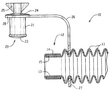
Referring more particularly to the drawings there is shown in Figs. 1 and 2 a
length of
corrugated rubber tubing 10 that has a central length portion with annular
corrugations 11
formed therein in accordance with the corrugated rubber tubing disclosed in
the patents listed
above and a rigid reinforced end socket 12. In accordance with the invention,
the end socket
12 comprises three coaxial layers or laminations including an axial inner
length portion 13 of
tubing, an axial inner length portion 13 of tubing, an axial outer length
portion 14 of tubing
and a metal collar 15 interposed between the length portions 13 and 14. In the
embodiment
215~'~~~
shown, the socket is of cylindrical form, however, it may also take other
forms in
different circumstances such as oval, rectangular, etc.
The end socket 12 is adapted for use in connection with an end plug 20 which
is
adapted to be tightly seated in the socket 12. The end plug 20 is a product
readily
5 available for the purpose intended and includes a cylindrical rubber body 21
and a
threaded fastener 22 extending axially therethrough. The fastener 22 has a
large head 23
adapted to bear against the inner end of the plug. The opposite end of the
threaded
fastener has a flat washer 24 thereon and a wingnut 25 which is used to
tightly seat the
end plug 20 in the socket 12. If desired, a retainer 26 may be used to secure
the plug 20
to the rubber tubing 10 when the plug is not in use. The retainer 26 has an
annular end
ring 27 at one end which fits in the groove portion between the corrugations
of the main
length portion 11 and an end ring 28 positioned between the washer 24 and the
outer end
of the rubber body 21.
As illustrated in Fig. 2, when the end plug 20 is inserted in the socket 12,
the
wingnut 25 may be tightened down on the threaded fastener 22 to cause axial
compression
of the rubber body 21 and resulting radial expansion. The radial expansion
forces the
outer cylindrical surface of the rubber body 21 into tight engagement with the
inner
surface of the socket 12 to secure the plug 20 in position. It will be noted
that without
the metal collar 15 to reinforce the socket, the tightening of the wingnut
would merely
serve to expand the end portion of the rubber tubing without causing any tight
engagement that would retain the plug in position. By using the metal collar
15,
sufficient rigidity is achieved to enable the end plug 20 to be effectively
utilized. Also,
coupling devices which require a rigid socket to provide adequate seating may
be used to
couple the rubber tubing in a desired manner.
Figs. 3 and 4 illustrate the manner in which the metal collar 15 is embedded
in the
rubber material to form the end socket 12. In accordance with the method of
the
invention, an extruded sleeve 30 of uncured rubber of a desired size for
forming the
particular product to be manufactured, is initially placed on the end of a
forming mandrel
-- ~ 2m~~~~
6
35 that is connected at one end to a pressure supply means. The mandrel is
supported in
cantilever fashion by a suitable support (not shown).
The mandrel 35 is initially coated with a lubricant such as a silicone
composition.
Also, the sleeve 30 may be lubricated by emersing it in a bath containing the
desired
lubricant. The mandrel 35 has a plurality of radial ports 36 formed therein
along a
discrete axial length portion thereof.
Initially, the sleeve 30 is disposed on the mandrel 35 and an external form
(not
shown) is positioned over the mandrel and sleeve. The external form is used to
provide
the desired preliminary shaping of the sleeve, i.e. to form rudimentary
corrugations 31
therein as accomplished in a manner similar to the general method of U.S.
Patents Nos.
3,168,604; 3,304,581; 3,669,586; 3,705,780; 3,975,129; 4,053,275; 4,113,828;
4,308,228; and/or 4,360,493.
Fig. 3 illustrates the uncured rubber sleeve 30 positioned on the mandrel 35
after
the rudimentary corrugations 31 have been formed in the central portion
thereof. The end
portion 32 remains on the mandrel in its original unformed condition and the
metal collar
15 is shown spaced from the end of the sleeve prepatory to positioning it over
the end
length 32.
At the appropriate time, the metal collar 15 is slid over the mandrel 30 and
end
length 32 into a position spaced from the end of the sleeve and overlying an
inner length
portion 33 (Figure 4). This leaves an outer length portion 34 between the
outer end of
the collar 15 and the end of the sleeve, that is approximately equal or
slightly greater than
the axial length of the collar. At this point, the outer length portion 34 is
folded back
over the collar so that the collar is entirely enclosed within the uncured
rubber material as
shown in dashed lines in Figure 4. This is easily accomplished since the
rubber in its
uncured condition is quite pliable and formable.
Once the forming of the rudimentary corrugations 31 and the assembly of the
metal collar 15 between the inner length portion 33 and outer length portion
34 is
7
completed, the resulting product is cured to set the corrugations and produce
the tubular
product 10 with the rigid reinforced end socket 12 in accordance with the
invention. To
accomplish the curing, the mandrel 35 itself may be used to support the
uncured rubber
sleeve 30 or the sleeve with the rudimentary corrugations 31 may be removed
from the
forming mandrel 35 and placed on a curing mandrel or pole for the curing
operation.
While the invention has been illustrated in connection with the forming of
flexible
rubber tubing with annular or helical corrugations, it will be understood that
the invention
may also be used in connection with various other types of rubber tubing for a
variety of
applications. Also, corrugated tubing of non-circular cross-section (such as
oval,
rectangular, etc.) may also be provided with an end socket 12 in accordance
with the
invention.
While the invention has been shown and described with respect to specific
embodiments thereof, this is intended for the purpose of illustration rather
than limitation
and other variations and modifications of the specific method and product
herein shown
and described will be apparent to those skilled in the art all within the
intended spirit and
scope of the invention. Accordingly, the patent is not to be limited in scope
and effect to
the specific embodiment herein shown and described nor in any other way that
is
inconsistent with the extent to which the progress in the art has been
advanced by the
invention.