Note: Descriptions are shown in the official language in which they were submitted.
21~~~~.f
EARLY EVALUATION SYSTEM
Background Of The Invention
1. Field Of The Invention
The present invention relates generally to methods and apparatus
for servicing a well, and more particularly to methods and apparatus
for the early evaluation of a well after the borehole has been drilled
and before casing has been cemented in the borehole.
2. Description Of The Prior Art
During the drilling and completion of oil and gas wells, it is
often necessary to test or evaluate the production capabilities of the
well. This is typically done by isclating a subsurface formation
which is to be tested and subsequently flowing a sample of well fluid
either into a sample chamber or up through a tubing string to the
surface. Various data such as pressure and temperature of the
produced well fluids may be monitored down hole to evaluate the long-
term production characteristics of the formation.
One very commonly used well testing procedure is to first cement
a casing in the borehole and then to perforate the casing adjacent
zones of interest. Subsequently the well is flow tested through the
perforations. Such flow tests are commonly performed with a drill
stem test string which is a string of tubing located within the
casing. The drill stem test string carries packers, tester valves,
circulating valves and the like to control the flow of fluids through
the drill stem test string.
Although drill stem testing of cased wells provides very good
test data, it has the disadvantage that the well must first be cased
before the test can be conducted. Also, better reservoir data can
y15~91fi
2
often be obtained immediately after the well is drilled and before the
formation has been severely damaged by drilling fluids and the like.
For these reasons it is often desired to evaluate the potential
production capability of a well without incurring the cost and delay
of casing the well. This has led to a number of attempts at
developing a successful open-hole test which can be conducted in an
uncased borehole.
One approach which has been used for open-hole testing is the use
of a weight-set, open-hole compression packer on a drill stem test
string. To operate a weight-set, open-hole compression packer, a
solid surface must be provided against which the weight can be set.
Typically this is accomplished either with a tapered rathole type
packer as shown in U. S. Patent Nos. 2,222,829 to Humason et al., or
with a perforated anchor which sets down on the bottom of the hole.
A disadvantage of the use of open-holE: compression set type packers
is that they can only be used adjacent the bottom of the hole. Thus,
it is necessary to immediately test a formation of interest after it
has been drilled through. These types of packers cannot be utilized
to test a subsurface formation located at a substantial height above
the bottom of the hole. Also, this type of test string is undesirable
for use offshore because the pipe string can become stuck in the open
borehole due to differential pressures between the borehole and
various formations. As will be understood by those skilled in the
art, when the pipe string is fixed and is no longer rotating, portions
of the pipe string will lie against the side of the borehole and
sometimes a differential pressure situation will be encountered
wherein the pipe string becomes very tightly stuck against the side
~1~591~
3
wall of the borehole . This is especially a dangerous problem when the
flow control valves of the test string are operated by manipulation
of the test string. In these situations, if the test string becomes
stuck it may be impossible to control the flow of fluid through the
test string.
Another prior art procedure for open-hole testing is shown in U.
S. Patent No. 4,246,964 to Brandell, and assigned to the assignee of
the present invention. The Brandell patent is representative of a
system marketed by the assignee of the present invention as the
Halliburton Hydroflate system. The Hydroflate system utilizes a pair
of spaced inflatable packers which arf~ inflated by a downhole pump.
Well fluids can then flow up the pipe string which supports the
packers in the well. This system stir has the disadvantage that the
pipe string is subject to differential sticking in the open borehole.
Another approach to open-hole testing is through the use of pad-
type testers which simply press a small resilient pad against the side
wall of the borehole and take a very small unidirectional sample
through an orifice in the pad. An example of such a pad-type tester
is shown in U. S. Patent No. 3,577,78l to Lebourg. The primary
disadvantage of pad-type testers is that they take a very small
unidirectional sample which is often not truly representative of the
formation and which provides very little data on the production
characteristics of the formation. It is also sometimes difficult to
seal the pad. When the pad does seal, it is subject to differential
sticking and sometimes the tool may be damaged when it is removed.
Another approach which has been proposed in various forms, but
which to the best of our knowledge has never been successfully
2~~~~1~
4
commercialized, is to provide an outer tubing string with a packer
which can be set in a borehole, in combination with a wireline-run
surge chamber which is run into engagement with the outer string so
as to take a sample from below the picker. One example of such a
system is shown in U. S. Patent No. 3,111,169 to Hyde, and assigned
to the assignee of the present inven~ion. Other examples of such
devices are seen in U. S. Patent No. 2,497,185 to Reistle, Jr.; U. S.
Patent No. 3,107,729 to Barry et al.; U. S. Patent No. 3,327,781 to
Nutter; U. S. Patent No. 3,850,240 to Conover; and U. S. Patent No.
3,441,095 to Youmans.
The present invention provides a number of improvements in open-
hole testing systems of the type generally proposed in U. S. Patent
3,111,l69 to Hyde.
Summary Of The Invention
In a first aspect of the present invention a system is provided
including an outer tubing string having an inflatable packer, a
communication passage disposed through the tubing string below the
packer, an inflation passage communica~ed with the inflatable element
of the packer, and an inflation valve controlling flow of inflation
fluid through the inflation passage. The inflation valve is
constructed so that the opening and closing of the inflation valve is
controlled by surface manipulation of the outer tubing string. Thus
the inflatable packer can be set in the well simply by manipulation
of the outer tubing string and applying fluid pressure to the tubing
string without running a surge chamber or other inner well tool into
the tubing string. After the packer has been set, an inner well tool
such as a surge chamber may be run into and engaged with the outer
2i~~9~.~
tubing string to place the inner well tool in fluid communication with
a subsurface formation through the communication passage.
In another aspect of the invention, a system similar to that just
described utilizes a retrievable straddle packer having upper and
lower packer elements, and includes a circulating valve located above
the upper packer element. The communication passage terminates
between the upper and lower packer elements. With this system, both
before and after the inner well tool is run into and engaged with the
outer tubing string, the circulatir_g valve may be utilized to
circulate fluid through the well annulus so that differential sticking
of the outer tubing string in the borehole is prevented.
In yet another aspect of the invention, the well fluid samples
are collected by running an inner tubing string, preferably an inner
coiled tubing string, into the previously described outer tubing
string. The coiled tubing string is engaged with the outer tubing
string and the bore of the coiled tubing string is communicated with
a subsurface formation through the communication passage defined in
the outer tubing string. Then well fluid from the subsurface
formation is flowed through the communication passage and up through
the coiled tubing string. Such a coiled tubing string may include
various valves for control of fluid flew therethrough. In a preferred
embodiment the coiled tubing string utilizes annulus pressure
responsive control valves which are controlled by pressure changes in
a tubing annulus defined between the coiled tubing string and the
outer tubing string.
In still another aspect of the present invention, the system can
be utilized to treat a subsurface formation. Instead of running a
21y91
6
surge chamber to collect a sample of fluid, a pressurized injection
canister is run into and engaged with the outer tubing string. The
pressurized injection canister is communicated with the subsurface
formation through the communication passage. A treatment fluid such
as acid can then be injected into the subsurface formation.
Numerous objects, features and advantages of the present
invention will be readily apparent to those skilled in the art upon
a reading of the following disclosure when taken in conjunction with
the accompanying drawings.
Brief Description Of The Drawings
FIGS. lA-1C comprise a series of three sequential schematic
representations of the use of a first embodiment of the invention
having an outer tubing string with a surge chamber, or an injection
canister or the like run on wireline into the outer tubing string.
FIG. lA illustrates the outer tubing string after it has been run into
the well to a position adjacent a subsurface formation of interest.
In FIG. 1B, the packers have been set in the uncased borehole and a
wireline-run surge chamber is being run down into the outer tubing
string. In FIG. 1C, the surge chamber is engaged with the surge
receptacle of the outer tubing string and a well fluid sample is
flowing into the surge chamber. FIGS. 2A-2C comprise a series of
three sequential schematic drawings illustrating a second embodiment
of the invention wherein the wireline-run surge chamber is replaced
with an inner coiled tubing string having a device on the lower end
thereof for engagement with the surge receptacle of the outer tubing
string. FIG. 2A shows the outer tubing string being run into the well
to a position adjacent a subsurface formation of interest. In FIG.
215~~~.~
2B, the packers have been set in the borehole and an inner coiled
tubing string is being run into place. In FIG. 2C, the inner coiled
tubing string has been engaged with the outer tubing string and well
fluid from the formation is being allowed to flow up through the
coiled tubing string.
FIGS. 3A-3J comprise an elevation sectioned view showing the
details of construction of a surge chamber and straddle packer
assembly like that schematically illustrated in FIG. lA. The assembly
is in a position with the packers retracted as it would be in when
being run into place in the well as represented in FIG. lA. D~
4A-4E comprise an elevation sectioned view of the assembly shown in
FIGS . 3A-3E, with the addition that a surge chamber is shown partially
run into place within the assembly in a manner similar to that
schematically represented in FIG. 1B. In FIGS. 4A-4E, the packers
have been inflated to set them within the uncased borehole as also
schematically illustrated in FIG. 1B.
FIGS. 5A-5E comprise a sectioned elevation view of the upper
portion of the assembly of FIGS. 3A-3E with the surge chamber engaged
in a position so that a well fluid sample is flowing from between the
packers into the surge chamber. This corresponds to the position
schematically illustrated in FIG. 1C.
FIGS. 6A-6E comprise an elevation sectioned view of the upper
portions of the assembly of FIGS. 3A-3E after the surge chamber has
been removed and with the assembly in an equalizing position wherein
pressure in the wellbore between the straddle packer elements is
equalized with pressure inside the outer tubing string.
..-
8
FIGS. 7A-7D comprise an elevaticn sectioned view of the outer
straddle packer assembly as seen in FIGS. 3A-3B with an inner coiled
tubing string and valve partially run into place therein in a manner
similar to that schematically illustrated in FIG. 2B.
FIGS. 8A-8D illustrate the apparatus of FIGS. 7A-7D with the
coiled tubing string engaged with the surge receptacle of the packer
assembly so that a well fluid sample ~~an flow up through the coiled
tubing string as schematically illustrated in FIG. 2C.
FIGS. 9A-9D illustrate the straddle packer assembly of FIGS. 3A-
3D having an injection canister partially received therein.
l0A-10D comprise an elevation sectioned view of the apparatus of FIGS.
9A-9D with the injection canister fully inserted so that pressurized
treatment fluid can be injected into the subsurface formation.
FIGS. 11A-11D comprise an elevation sectioned view of yet another
embodiment of the invention illustrating the use of a surge chamber
similar to that shown in FIGS. 3A-3J which also carries a pressure
gauge which monitors the pressure of the well fluid.
FIG. 12 is a laid-out view of a J--slot of the apparatus of FIGS.
3A-3J. This J-slot controls the opening and closing of an inflation
passage so that the inflation and deflation of the packers can be
controlled by manipulation of the outer tubing string to which the
packers are attached.
FIG. 13 is a schematic elevation partially sectioned view of
another embodiment of the invention utilizing an annulus pressure
responsive coiled tubing drill stem test string located within an
outer tubing string which carries inflatable packers and a downhole
pump.
2~~591G
9
FIG. 14 is a schematic elevation, partially sectioned view of yet
another embodiment of the invention which is similar to that of FIG.
13 but which utilizes a compression set packer rather than inflatable
packers on the outer tubing string.
Detailed Description Of The Preferred Embodiments
General Description Of The Methods Schematically Illustrated in FIGS.
lA-1C and 2A-2C
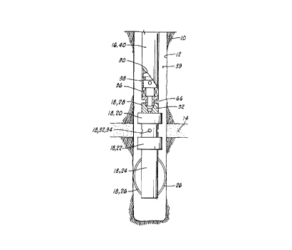
FIGS. lA-1C schematically illustrate a method of servicing a well
having an uncased borehole 12 intersecting a subsurface formation
or zone 14. As used herein, a reference to a method of servicing a
well is used in a broad sense to include both the testing of the well
wherein fluids are allowed to flow from the well and the treatment of
a well wherein fluids are pumped into the well.
As illustrated in FIG. lA, first an outer tubing string generally
designated by the numeral 16 is run into the well 10. The outer
tubing string includes a straddle packer assembly 18 having upper and
lower inflatable packer elements 20 and 22, respectively. A lower
housing 24 extends below the lower packer element 22 and has belly
springs 26 extending radially therefrom and engaging the borehole 12
to aid in setting of the straddle packer 18.
By incorporating a swivel above the outer tubing string 16, the
outer tubing string 16 can be rotated to aid in preventing
differential sticking as the outer tubing string 16 is lowered into
place.
The straddle packer 18 includes an inflation valve assembly 28
which controls flow of fluid from the interior 30 of the outer tubing
string 16 to the inflatable elements 20 and 22 through an inflation
10
passage which is further described below with regard to FIGS. 3A-3J.
The straddle packer 18 has a communication passage 32 defined
therein including a plurality of ports 34 located between packer
elements 20 and 22. The communication passage 32 communicates with
the interior 30 of tubing string 16.
A well annulus 39 is defined between the uncased borehole 12 and
the outer tubing string 16.
The outer tubing string 16 further includes a position
correlation sub 36 and a circulating valve 38. All of these
components are carried on an elongated string of tubing 40.
The correlation tool 36 preferably is a correlation sub having
a radioactive tag therein which can be used to determine accurately
the position of the outer tubing string 16 through the use of a
conventional wireline run correlation tool which can locate the
radioactive tag in correlation sub 36.
Typically after the borehole 12 has been drilled an open hole log
will be run so as to identify the various zones of interest such as
subsurface formation 14. Then the outer tubing string 16 is run into
the well and located at the desired depth as determined by the
previously run open hole log through the use of the correlation sub
36.
The tubing string 16 is run into the uncased borehole 12 as shown
in FIG. lA until the straddle packer elements 20 and 22 are located
above and below a subsurface zone or formation 14 which is of
interest.
Then the inflatable elements 20 and 22 are inflated to set them
within the uncased borehole 12 as shown in FIG. 1B. As further
11
described below with regard to FIGS. 3A-3J, the inflation and
deflation of elements 20 and 22 is controlled by physical manipulation
of the tubing string 16 from the surface.
In FIG. 1B an inner well tool 42 is being lowered into the outer
tubing string 16 on a wireline 44. The inner well tool 42 includes
a stinger element 46 on the lower end thereof which is adapted to be
received in a seal bore 48 defined in the straddle packer assembly 18.
In FIG. 1C, the inner well tool 42 has been lowered into
engagement with the outer tubing string 16 until the stinger element
46 is closely received within the seal bore 48 thus placing the inner
well tool 42 in fluid communication with the subsurface formation 14
through the communication passage 32.
In one embodiment further illustrated in FIGS. 3-6 and 11, the
inner well tool 42 is a surge chamber which collects a fluid sample
from the subsurface formation 14 which can then be retrieved by
retrieving the surge chamber with the wireline 44. In another
embodiment illustrated in FIGS. 9 and 10, the inner well tool 42 is
a pressurized fluid injection canister which will inject a treatment
fluid into the subsurface formation 14 through the communication
passage 32.
FIGS. 2A-2C comprise a similar sequential series of schematic
sketches wherein the wireline conveyed inner well tool 42 has been
replaced by a modified inner well tool 42A which is defined on the
lower end of inner coiled tubing string 50. In this embodiment when
the stinger 46 is engaged with the seal bore 48 as illustrated in FIG.
2C, fluid from the subsurface formation 14 can be flowed upward
through the coiled tubing string 50 to a surface location. Also,
.--
12
treatment fluids can be pumped down through the coiled tubing 50 into
the subsurface formation 14. The details of construction of this
embodiment are further illustrated in FIGS. 7 and 8.
Detailed Description Of The Embodiments Of FIGS. 3-6
FIGS. 3A-3J comprise an elevation right-side only sectioned view
of the straddle packer assembly 18 in an initial positions with the
inflatable elements 20 and 22 deflated or retracted as they would be
when the outer tubing string 16 is first run into a well as
schematically illustrated in FIG. 1A.
The straddle packer assembly 7.8 includes an outer housing
assembly 52 made up of an upper collar 54, an oil chamber housing
section 56, a load shoulder housing section 58, a packer mandrel
section 60, an adapter section 62, the lower housing 24 which carries
belly spring 26, and a lower plug 64. All of the components of outer
housing assembly 52 are connected together by threaded connections
with appropriate O-ring seals as shown.
The packer assembly 18 further includes an inner sliding mandrel
66 having an upper adapter 68 connected to the upper end thereof . The
upper adapter 68 has a female thread 70 for connection of the packer
assembly 18 to the various components of tubing string 16 located
thereabove such as for example the position correlation sub 36
schematically illustrated in FIG. lA. The sliding mandrel 66
includes a cylindrical outer surface 72 which is closely and slidably
received within a bore 74 of upper collar 54.
As will be further described below, the sliding mandrel 66 slides
relative to the outer housing assembly 52 in a sequence controlled by
an endless J-slot 76 cut in the outer surface of sliding mandrel 66,
~1559~~
13
and one or more lugs such as 78 carried by the outer housing assembly
52 and received in the endless J-slot 76. A laid-out view of J-slot
76 is shown in FIG. 12.
The movement of sliding mandrel 66 relative to housing assembly
52 is made possible by the belly springs 26 which fractionally engage
the uncased borehole 12 to hold the housing assembly 52 fixed relative
to borehole 12 as the outer tubing string 16 is physically manipulated
from the surface.
Also, the extreme positions of sliding mandrel 66 relative to
housing assembly 54 and the load transferring positions are defined
by engagement of a large radially outward extending annular load
shoulder 80 defined on sliding mandrel 66 which can abut downward and
upward facing load transfer surfaces 82 and 84 of housing assembly 52
as seen in FIG. 3C.
The lugs 78 are carried by housing assembly 52 on a rotatable lug
sleeve 85 received between upper and ~_ower bearings 86 and 88. The
J-slot and lugs 76, 78 and the load transfer shoulder 80 a11 operate
in a clean, lubricated environment defined by an oil chamber 87 which
extends from seals 88 and 90 of a floating piston 92 at the upper
extremity to seals 94 and 96 at the lower extremity. The oil chamber
87 may be filled with oil through a port 98 which is closed by plug
100. The floating piston 92 has an air chamber 102 located thereabove
and allows for expansion and contraction of the oil in oil chamber 87.
When the straddle packer assembly 18 is first lowered into the
well 10, it is in its extended most position with the annular load
21~59~~
14
transfer shoulder 80 abutting the downward facing load transfer
surface 82.
With reference to FIGS. 3E-3H, it is noted that the upper
inflatable element 20 has a fixed upper shoe 102 fixedly attached to
housing assembly 52 at thread 104. "_'he lower end of upper packer
element 20 is bonded to a sliding shoe 106 which is in turn connected
at threaded connection 108 to a sliding packer sleeve 110 which has
its lower end connected at thread 112 to an upper sliding shoe 114 of
lower packer element 22. The lower packer element 22 is bonded at its
lower end to a lower sliding shoe assembly 116 which carries O-ring
seals 118 and 120 which sealingly and slidingly engage a cylindrical
outer surface 122 of packer mandrel 60.
The ports 34 of communication passage 32 previously briefly
described with regard to FIG. lA, are defined in the sliding packer
sleeve 1l0 as shown in FIG. 3F. The communication passage 32 further
includes a thin annular space 124 defined between the outer surface
122 of packer mandrel 60 and a cylindrical inner surface 126 of
sliding packer ring 110.
Communication passage 32 further includes a plurality of
intermediate radial bores 128 which communicate the annular space 124
with a longitudinal bore 130 defined in packer mandrel 60 and having
a blind upper end 132. Adjacent the blind end 132 the communication
passage 32 includes an offset portion 134 which communicates with a
plurality of radially inwardly open pots 136 (see FIG. 3D) defined
in the seal bore 48.
A communication valve 138 is located in the seal bore 48 for
controlling flow of fluid through the communication passage 32 just
215591
described. The communication valve 138 includes a valve element 140
which is biased upwardly by a valve spring 142. Valve element 140
carries upper and lower O-ring seals 144 and 146. The uppermost
position of valve element 140 is defined by abutment thereof with a
snap ring 148 received in a groove 150 cut into the seal bore 48.
When the valve element 140 is biased by spring 142 to its
uppermost position as shown in FIGS. 3D-3E, the upper and lower O-
rings seals 144 and 146 are located above and below the port 136 of
communication passage 32 as seen in FIG. 3D, thus maintaining the
communication passage 32 closed so that there is no fluid flow
therethrough.
As is further described below in connection with FIGS. 5A-5E,
when the inner well tool 42 is lowered into engagement with the outer
tubing string 16 as schematically illustrated in FIG. 1C, the stinger
46 of inner well tool 42 will engage the communication valve 138 thus
pushing it downwardly so that O-ring 144 moves below port 136 thus
opening the communication passage 32 to provide communication of the
subsurface formation 14 with the inner well tool 42.
As seen in FIG. 3E, the longitudinal bore 130 of communication
passage 32 is intersected by a diagonally oriented equalizing passage
152 which has an equalizing port 154 defined at its upper end as seen
in FIG. 3D. As is further explained below with regard to FIGS. 6A-6E,
the equalizing passage l52 is used to equalize fluid pressure between
the interior 30 of tubing string 16 and the well annulus 39 sealed
between upper and lower packer elements 20 and 22 prior to deflation
of the packer elements and retrieval of the tubing string 16.
21559e
16
A fluid relief passage 157 communicates seal bore 48 below lower
O-ring 146 with the interior 30 of tubing string 16 located thereabove
so as to prevent hydraulic blocking of movement of the valve member
140.
The inflatable packer elements 20 and 22 are communicated with
the interior 30 of tubing string 16 by an inflation passage 156 which
begins at its upper end at a radially inwardly open inflation port 158
(see FIG. 3D) and then extends longitudinally downward through the
packer mandrel 60 to terminate in a lower port 160 which communicates
with a thin annular space 162 defined between packer mandrel 60 and
upper packer element 20. The thin annular space 162 in turn
communicates with a longitudinal passage 164 defined through sliding
packer sleeve 110 which communicates with another thin annular space
166 defined between packer mandrel 60 and lower packer element 22.
As is apparent in viewing FIG. 3D, sliding movement of the
sliding mandrel 66 relative to the housing assembly 52 will determine
whether the inflation passage 156 is opened or closed. It will
similarly determine whether the equalizing passage 152 is opened or
closed.
The sliding mandrel 66 carries first, second and third seals 96,
168 and 170, respectively, which are sealingly received within a bore
172 of packer mandrel 60. Sliding mandrel 66 further includes a
plurality of equalizing ports 174 defined therethrough between the
first and second seals 96 and 168. The packer mandrel 60 carries an
O-ring 176 located immediately above the equalizing port 154.
When the sliding mandrel 66 is in its initial uppermost position
relative to housing assembly 52 as illustrated in FIGS. 3A-3D, and as
17
2155916
defined by abutment of the load transfer shoulder 80
with the downward facing load transfer surface 82, the
equalizing passage 152 is closed and the inflation
passage 156 is opened as seen in FIG. 3D.
As seen in FIGS. 3G and 3H, an electronic
gauge carrier 178 which is cylindrical in shape is
received within a lower bore 180 of packer mandrel 60
and communicates through the longitudinal bore 130
with the communication pas.~age 32. The electronic
~o gauge carrier 178 includes sensing devices such as
pressure and temperature sensors which monitor and
record the pressure and temperature of the well fluids
which flow through the communication passage 32 when
the inner well tool 42 is communicated with formation
14 as further described below. The electronic gauge
carrier 178 may for example be a HMR tool available
from Halliburton Company. The details of construction
of such a downhole gauge carrier may be as shown in
U.S. Patent No. 4,866,607 to Anderson et al.
2o When the outer tubing string 16 is located
in the position such as ;schematically illustrated in
FIG. lA with the upper packer element 20 located above
the subsurface formation 14 and with the lower packer
element 22 located below the subsurface formation 14,
the packer elements 20 and 22 can be inflated. The
circulating valve 38 must be closed and then by
increasing fluid pressure in the interior 30 of outer
tubing string 16 approximate.Ly 800 to 1000 psi that
pressure is transmitted through the open inflation
3o passage 156 as seen in FIGS. 3A-3H to inflate the
inflatable packer elements 20 and 22 thus setting them
in the uncased borehole 12 as schematically
illustrated in FIG. 2B.
215 9 ~.~
18
In the detailed drawings of FIGS . 4A-4E, the upper packer element
20 is shown in an inflated position and the inflation passage 156 has
now been closed to trap the inflation pressure in the inflatable
elements 20 and 22. The inflation passage 156 is closed by moving the
sliding mandrel 66 downward relative to housing assembly 52 in the
following manner.
FIGS. 4A-4E illustrate the upper portions of packer assembly 18
as just described with regard to FIGS. 3A-3E after the outer tubing
string 16 has been manipulated to move the sliding mandrel 66 to a
lower position relative to housing assembly 52 as defined by movement
of lugs 78 to an upper position within J-slot 76 as seen in FIG. 4B.
As seen in FIG. 4D, this moves the lowermost seal 170 of sliding
mandrel 66 to a position below the ports 158 of inflation passage 156
to close inflation passage 156. The lower portions of the packer
assembly 18 are the same as shown i.n FIGS. 3F-3J.
After the inflation passage 156 has been closed off as shown in
FIG. 4D, the circulating valve 38 can be reopened if desired to allow
continuing circulation of well fluids through the well annulus 39 to
prevent differential sticking of outer tubing string 16 during the
subsequent operations.
After the sliding mandrel 66 has been moved to the position shown
in FIGS. 4A-4D, thus trapping inflation pressure in the inflatable
elements 20 and 22 so they will remain set within the borehole 12 as
schematically illustrated in FIG. 1B, the inner well tool 42 can be
lowered on wireline 44 into the outer tubing string 16 as also
schematically illustrated in FIG. 1B.
2155e.6
19
In FIGS. 4A-4D, the inner well tool 42 is shown partially lowered
into position within the packer assembly 18 of outer tubing string 16
as was schematically illustrated in FIG. 1B. The stinger 46 has not
yet been engaged with the seal bore 48 as can be seen in FIG. 4D.
The inner well tool 42 shown in FIGS. 4A-4D is a surge tool 42.
A threaded connection 181 at the upper end of surge tool 42 allows
connection thereof to the wireline 44 in a known manner. The wireline
44 is not illustrated in FIG. 4A.
The surge tool 42 includes a surge tool housing assembly 182
which is made up of upper connector 184, adapter 186, sample housing
l88, upper valve housing 190, lower valve housing 192, lower surge
tool housing shell l94, orifice housing 196, and dump chamber housing
198.
A sliding sample valve assembly 200 having upper and lower parts
202 and 204 threadedly connected at thread 206 is slidably received
within the surge tool housing assembly 182.
Lower part 204 of sliding valve sleeve assembly 200 includes an
enlarged diameter portion carrying an O-ring seal 208 which is
sealingly received within a bore 210 of lower valve housing 192.
Located below the sliding valve sleeve assembly 200 and
particularly below O-ring 208 is an oil-filled oil chamber 212. As
is further described below, downward movement of sliding sample valve
assembly 200 is slowed due to the time required to force the oil from
oil chamber 212 through an orifice 214 into an empty dump chamber 216
defined in dump chamber housing 198.
The lower surge tool housing shell 194 has a lower inner bore 218
within which the stinger member 46 is slidably received as seen in
~1559~.~
FIG. 4D. Lower surge tool housing shell l94 has a surge passage 220
defined therein which has a port 222 at its lower end communicated
with bore 218 and which is communicated at its upper end with a thin
annular space 224 defined between lower surge tool housing shell l94
on the outside and dump chamber housing 198, orifice housing 196, and
lower valve housing 192 on the inside.
First, second and third O-ring seals 226, 228 and 230 are located
in the bore 218 of lower surge tool housing shell 194. The port 222
is located between first and second O-ring seals 226 and 228. The
stinger 46 is held in an initial position shown in FIG. 4D by a
plurality of shear pins 232. Stinger 46 includes a stinger passage
234 having ports 236 and 238 at its lower and upper ends,
respectively. When the stinger 46 is in its initial position, the
upper port 238 is located between second and third O-rings 228 and 230
and is thus isolated from port 222 so that fluids cannot flow in
through the stinger 46 into the surge tool 42.
The stinger 46 carries an outer O-ring seal 254 which will
subsequently be received in the seal bore 48 of packer assembly 18.
The thin annular space 224 is communicated with first and second
power ports 240 and 242 defined through lower valve housing 192 above
the O-ring seal 208 of valve member 200. When high pressure formation
fluids are subsequently communicated with the stinger passage 234 in
a manner further described below, they will be communicated through
the thin annular space 224 to the power ports 240 and 242 thus causing
the valve member 200 to begin slowly moving downward within the valve
housing 190, 192. The valve member 200 carries an O-ring seal 244
(see lower portion of FIG. 4B) which after a short movement of valve
21 2155916
member 200 will move below the second power port 242.
After that time, the second power port 242 serves as a
sampling port and will flow a sample of well fluid
through an irregularly shaped sampling passage 246
into a sample chamber 248. The details of construction
of the sampling passage and associated structure are
similar to those shown in U.S. Patent No. 5,058,674 to
Schultz et al.
A floating piston 250 is located above
~o sliding sample valve assembly 200. As the sample
chamber 248 fills with well fluid, the floating piston
250 will move upward until it abuts a lower end 252 of
adapter l86.
The volume of the sample to be taken can be
varied by varying the size of the surge chamber 248.
Turning now to FIGS 5A-5E, the components of FIGS. 4A-
4E are shown in the position wherein the stinger 46
has been stabbed into the seal bore 48 thus placing
the upper port 134 of communication passage 32 in
zo communication with the surge passage 220 through the
stinger 46. This is accomplished in the following
manner.
As the stinger 46 v~s inserted into the seal
bore 48, the 0-ring seal 254 will be sealingly
received in the seal bore 48. A lower end 255 of
stinger 46 will abut an upper end 256 of communication
valve element 140 thus compressing valve spring 142
and moving the communication valve element 140 down-
ward to the position shown in FIG. 5D wherein the
3o upper port 134 of communication passage 132 is
uncovered. The valve element l40 bottoms out in seal
bore 48, and then the shear pins 232 which initially
held stinger 46 in place relative to lower surge tool
housing shell l94 will shear thus
2~.~59~.6
22
allowing the stinger 46 to move upward within bore 218 to the position
shown in FIG. 5D wherein the stinger passage 234 is communicated with
the port 222 of surge passage 220 thus placing the surge passage 220
in fluid communication with the subsurface formation 14 through the
communication passage 32.
Then, as previously described, well fluid will flow upward
through the thin annular space 224 and in through power ports 240 and
242 to begin pushing the sample valve assembly 200 downward. This
downward movement is controlled by the metering of oil from orifice
chamber 212 through orifice 214 into dump chamber 2l6. When seal 244
of sample valve assembly 200 moves below power port 242, that well
fluid will then flow through the power port 242 and through the
irregularly shaped sampling passage 246 into the sample chamber 248
below floating piston 250. The sample chamber 248 will fill
relatively quickly until the floating piston 250 has moved upward into
abutment with lower end 252 of adapter 186. This will be accomplished
long before the downward sliding movement of sample valve member 200
has been completed. The sample valve member 200 will move downward
until downward facing shoulder 258 abuts an upper end 260 of upper
valve housing 190. At this time, O-rings 264 and 266 will have moved
below slotted ports 268 of sampling passage 246 to trap the sample
within sample chamber 248.
The sampling tool or surge tool 42 can then be retrieved with the
wireline 44 thus retrieving the sample to the surface. When the
sample chamber 42 is pulled out of engagement with the seal bore 48,
the valve spring 142 will move the communication valve 140 back up to
its closed position of FIG. 4D.
~15~91~
23
If it is desired to take additional samples, additional surge
tools 42 can be lowered into engagement with the seal bore 48 in a
like manner.
Also, a pump could be incorporated into the surge chamber 42 to
artificially produce the subsurface formation 14. This can also be
utilized to insure that a clean well fluid sample is taken.
When it is desired to move the outer tubing string 16 to another
location in the well or to retrieve it from the well, the pressure in
interior 30 of outer tubing string 16 should first be balanced with
the pressure trapped in the well annulus 39 between the upper and
lower packer elements 20 and 22.
When the formation 14 is tested, the pressure between the packers
20 and 22 drops as it surges into the sample chamber. The equalizing
position increases the pressure between the packers to make it more
nearly equal to the hydrostatic pressure present in the annulus above
and below the packers. This is accomplished by physical manipulation
of the outer tubing string as controlled by J-slot and lug assemblies
76, 78 to move the sliding mandrel 66 to a position as shown in FIGS.
6A-6D wherein equalizing ports 174 are moved below O-ring seal 176 so
as to place equalizing passage 152 in fluid communication with
interior 30 of outer tubing string 16.
After that pressure has equalized, the sliding mandrel 66 can be
pulled upward by tubing string 16 to return to the position shown in
FIGS. 3A-3J thus allowing the packer elements 20 and 22 to deflate so
that the outer tubing string is again in a position as illustrated in
FIG. lA and can be moved to another location within the borehole 12
or retrieved from the well 10.
21~59~.6
24
The J-Slot And Lug Of FIG. 12
In FIG. 12, a laid-out view is shown of the J-slot 76 and lug
78, illustrating the various positions of the lug 78 within the J-slot
76. The lug 78 is in a first position 78A when the sliding mandrel
66 is in its initial uppermost position relative to the housing
assembly 52 as illustrated in FIGS. 3A-3D whereby the inflation
elements 20 and 22 of the packer 18 are deflated. After the inflation
elements 20 and 22 are inflated, the sliding mandrel 66 is moved to
its lowermost position relative to the housing assembly 52 as
illustrated in FIGS. 4A-4E. When the sliding mandrel 66 is moved to
its lowermost position, the lug 78 is in its second position 78B and
inflation pressure is trapped within the inflation elements 20 and 22.
Prior to deflating the inflation elements 20 and 22, the sliding
mandrel 66 is moved to an intermediate position whereby the lug 78 is
in a third position 78C and whereby the fluid pressure between the
interior 30 of the tubing string 16 and the well annulus 39 sealed
between the inflated packer elements 20 and 22 is allowed to equalize
by way of the diagonal equalizing passage 152. After such
equalization, the sliding mandrel 66 is again moved to its lowermost
position whereby the lug 78 is in a fourth position 78D, the
equalization passage 152 is closed and the packer elements remain
inflated. Finally, the sliding mandrel 66 is moved to its uppermost
position whereby the lug 78 returns to its first position 78A and the
packer elements 20 and 22 are deflated.
Details Of Construction Of The Embodiment Of FIGS. 7 And 8
In FIGS. 7A-7D a structure corresponding to that schematically
illustrated in FIG. 2B is shown. A coiled tubing string 50 has been
21~591~
partially lowered into the outer tubing string 16 so that the stinger
46 is located just above the seal bore 48 as seen in FIG. 7D. It will
be recognized that the stinger 46, seal bore 48 and associated
structures shown in FIG. 7D are substantially identical to and in a
position analogous to that shown in FIG. 4D and described above. The
only difference is that the stinger 46 is now attached to the coiled
tubing string 50 rather than to the surge tool 42.
As schematically illustrated in FIG. 2B, the coiled tubing string
50 has a modified inner tool 42A defined on the lower end thereof.
This modified inner tool 42A includes a hollow housing 270 constructed
similar to the lower portion of the lower surge tool housing shell 194
described above with regard to FIG. 4D. The hollow housing 270
has a surge passage 272 defined therethrough which is communicated
with a coiled tubing bore 274 of coiled tubing string 50.
In the position shown in FIG. 7D, the stinger 46 is held in place
in its initial position by shear pins 276 wherein surge passage 272
is closed. The stinger 46 is received in a bore 278 of hollow housing
270 and engages first, second and third O-ring seals 280, 282 and 284.
A stinger passage 286 is defined in stinger 46.
When the stinger 46 is lowered into engagement with the
communication valve 140, the communication valve 140 and the stinger
46 are both moved to open positions thus placing the coiled tubing
bore 274 in communication with subsurface formation 14 as illustrated
in FIG. 8D.
Stinger 46 with stinger passage 286 and the surge passage 272
along with the three O-ring seals 280, 282 and 284 provide a closure
valve on the lower end of the coiled tubing string 50 which may be
215e 16
26
generally referred to as a coiled tubing closure valve. This closure
valve is maintained in closed position as shown in FIG. 7D as the
coiled tubing is run into the well. After the stinger 46 is engaged
with seal bore 48 as illustrated in F IG . 8D, the coiled tubing closure
valve is moved to an open position substantially simultaneously with
engaging the stinger 46 with the outer tubing string 16 thereby
placing the interior of the coiled tubing string 50 in communication
with the subsurface formation 14 through the communication passage 32.
Details Of Construction Of The
Embodiment Of FIGS. 9 And 10 Utilizing
An Injection Canister For Treating The Well
FIGS. 9A-9D again show the upper portion of the packer assembly
18 in a position similar to that described above with regard to FIGS.
4A-4E wherein the inflatable elements 20 and 22 have been set in the
open borehole 12 in a manner like that schematically illustrated in
FIG. 1B. In FIGS. 9A-9D, an inner well tool which is more
specifically described as an injection canister 300 is shown partially
lowered into the packer assembly. The injection canister 300 would
be lowered into place on a wireline 44 just like the inner well tool
42 shown schematically in FIG. 1B.
The injection canister in fact utilizes many of the components
of the sampling tool 42 illustrated in FIGS. 4A-4D, but the injection
canister 300 operates in a very different manner. The injection
canister 300 carries a pressurized fluid such as acid therein which
will be injected into the subsurface formation 14 when the injection
canister 300 is mated with the seal bore 48 as shown in FIGS. 10A-10D.
The injection canister 300 includes a canister housing assembly
27
302 made up of an upper connector piece 304, a nitrogen chamber
housing 306, an acid chamber housing 308, upper valve housing 3l0,
lower valve housing 312, lower housing shell 314, orifice housing 3l6,
and dump chamber housing 3l7. An adapter 318 supports orifice valve
nosepiece 320 from orifice housing 316. An orifice valve sleeve 322
is slidably received on nosepiece 320.
A sliding valve assembly 324 made up of upper part 326 and lower
part 328 is slidably received in the valve housing 310, 312 in a
manner identical to that described above with regard to the valve
member 200 seen in FIGS. 4B-4C.
An oil chamber 324 is defined in the lower valve housing section
312 below an O-ring seal 326 of sliding valve member 24. The oil
chamber 324 is filled with oil down through the interior of orifice
housing 316, adapter 318, and a small axial bore 328 of orifice valve
nosepiece 320. A small radial port 330 is defined through the wall
of nosepiece 320 and communicates with oil chamber 324. In the
position shown in FIG. 9C, the orifice valve sleeve 322 is held in
place by a shear pin 332 so that the port 330 is blocked by the upper
portion of valve sleeve member 322. It is noted that the valve sleeve
member 322 has a sleeve port 334 defined therein. In a manner further
described below, the orifice valve sleeve 322 is moved upward relative
to nose 320 shearing shear pin 332 and moving port 334 into registry
with port 330 to allow oil to slowly meter therethrough from the oil
chamber 324 into a dump chamber 336 defined in dump chamber housing
317.
Located above and surrounding an upper portion of the valve
member 324 above an O-ring 338 is an acid chamber 340 filled with acid
215~9~6
28
or other liquid which is to be injected under pressure into the
subsurface formation 14. A floating piston 342 is located in the top
of acid chamber 340 and separates the acid in acid chamber 340 from
pressurized nitrogen gas or other gas located in nitrogen chamber 344.
The lower housing shell 3l4 seen in FIG. 9D has a bore 346
defined therethrough with a counterbore 348 located below bore 346.
The counterbore 348 carries first, second and third O-ring seals 350,
352 and 3S4.
A stinger 356 is slidably received in the lower housing shell
314. Stinger 356 includes an upper por~ion having a cylindrical outer
surface 358 closely received through bore 346, and an intermediate
portion having a cylindrical outer surface 360 closely received in
counterbore 348.
Stinger 356 includes a stinger passage 362 having a port 364
communicated with cylindrical outer surface 360. Shear pins 366
initially holds stinger 356 in the pos-~tion shown in FIG. 9D with the
port 364 located between O-ring seals 352 and 354. A fluid injection
passage 368 is defined in lower housing shell 314 and has a lower port
370 communicated with counterbore 348. In the position of FIG. 9D,
the injection passage 368 is closed by stinger 356.
The upper portion of stinger 356 as mentioned extends through
bore 346 of lower housing shell 314. It also extends through a bore
372 of dump chamber housing section 317 and engages an O-ring seal 374
therein.
When the injection canister 300 is lowered into engagement with
the seal bore 48 as shown in FIGS. 10A-10D, the communication valve
member 140 is pushed downward to an open position, then shear pin 366
21559.
29
is sheared allowing stinger 356 to move upward within counterbore 348
until an upward facing shoulder 376 of stinger 356 abuts a downward
facing shoulder 378 of lower housing shell 314.
As the uppermost portion of stinger 356 which extends through the
bore 372 of dump chamber housing section 317 moves upward, an upper
end 380 thereof engages a lower end 382 of orifice valve sleeve 322.
The orifice valve sleeve 322 is pushed upward thus shearing shear pin
332 and allowing the sleeve 322 to move upward relative to nosepiece
320 until the ports 334 and 330 are in registry with each other.
Then, the sliding valve assembly 324 can move downward due to the
differential pressure acting thereacross and force oil out of oil
chamber 324 through the aligned orifices 330 and 334 into the dump
chamber 336. Sliding valve assembly 3'?4 will move downward slowly due
to this metering effect.
When the O-ring seal 338 of sliding valve assembly 324 moves
below a port 384 in the lower valve housing 312, the pressurized acid
in acid chamber 340 can escape through port 384 and then flow downward
through a thin annular space 386 between outer housing shell 314 on
the outside and lower valve housing 312, orifice housing 316, and dump
chamber housing section 317 on the inside. The annular space 316 is
communicated with the injection passage 368 through which it flows to
stinger passage 362 and then to communication passage 32 through which
it is communicated with a subsurface formation 14. The metering of
oil through orifices 330 and 334 provides a time delay after stabbing
into the seal bore and prior to actual release of the acid through
port 384.
30
The pressurized nitrogen contained in nitrogen chamber 344 will
expand pushing floating piston 342 downward thus displacing the acid
contained in acid chamber 340 through the path just described. Thus
the subsurface formation 14 can be treated with acid or other liquid
through use of the injection canister 300. Then the injection
canister 300 can be retrieved with wireline 34 and subsequently a flow
test utilizing the surge tool 42 can be performed as previously
described.
Detailed Description Of The Embodiment Of FIGS. 11A-11D
FIGS. 11A-11D comprise an elevation, right-side only sectioned
view of a modified version of the wireline conveyed surge tool of
FIGS. 3-7 wherein a gauge carrier has been incorporated in the inner
tool which is run on the wireline. This self-contained gauge carrier
will be placed in fluid communication with the subsurface formation
14 when the apparatus is engaged with the seal bore 48 and can then
monitor various parameters such as pressure of the well fluid in the
subsurface formation 14 prior to and during the flowing of the well
fluid sample into the sample chamber.
The inner well tool shown in FIGS. 11A-11D is generally referred
to by the numeral 400 and can be described as a combined sampler/gauge
carrier 400.
In FIGS. 11A-11D the sampler/gauge carrier 400 has been lowered
on wireline 44 into engagement with the seal bore 48 and corresponds
to the position schematically illustrated in FIG. 1C. The surge
chamber and lower end of the apparatus 400 including the stinger are
identical in construction to and are in the identical positions
21~~91~
31
previously illustrated and described with regard to FIGS. 5A-5D. Like
identifying numerals have been utilized for the like components.
The difference lies in the construction of the part which in
FIGS. 5A-5D was referred to as the lower surge tool housing shell 194
which terminated at a threaded connection 195 where it is attached to
the lower valve housing 192.
In the embodiment of FIGS. 11A-11D, the surge tool housing shell
is denoted by the numeral 402 and is still connected to the lower
valve housing 192 at a thread 404 analogous in position to the thread
195 of FIG. 5C. In the embodiment of FIGS. 11A-11D, however, the
housing shell 402 extends upward beyond thread 404 and beyond the
upper end of the sample chamber as seen in FIG. 11A where it attaches
at thread 406 to a gauge carrier housing 408. A downhole memory gauge
410 is contained within gauge housing 408. The details of
construction of the electronic components of downhole memory gauge 410
may be similar to those described in Anderson et al. U. S. Patent No.
4,866,607.
A threaded wireline connection 412 is provided at the upper end
of gauge carrier housing 408 for connection to the wireline 44. A
pressure transducer 414 is associated with the downhole memory gauge
410 and is exposed to a fluid chamber 416 which in turn is
communicated with the subsurface formation 14 in the following manner.
A thin annular space 418 is defined between the surge tool
housing shell 402 on the outside and the outer surface of the surge
tool housing assembly 182 on the inside. The annular space 418
includes the space below thread 404 which in the embodiment of FIGS.
4A-4D was referred to as the annular space 224. The annular space 418
~~.~~916
32
above and below the threads 404 is communicated together by a groove
(not shown) in the threads 404.
At its lower end, the thin annular space 418 communicates with
the surge passage 220 which in turn communicates with stinger passage
234 and then with the communication passage 32 which leads to
subsurface formation 14.
Thus with the embodiment of FIGS. 11A-11D, as soon as the stinger
46 is engaged with the seal bore 48 to open the communication valve
138, and to move the stinger 46 to the position shown in FIG. 11D
wherein stinger passage 234 is communicated with surge passage 220,
the pressure transducer 414 will be in fluid communication with the
subsurface formation 14 and thereafter can monitor pressure and other
parameters until such time as the apparatus 400 is withdrawn from
engagement with seal bore 48 by means of wireline 44.
Data taken during and after surging of the formation 14 may
provide usable drawdown and buildup test data.
The Embodiments Of FIGS. 13 And 14
Utilizing Concentric String Annulus Pressure
Responsive Testing In An Uncased Borehole
FIGS. 13 and 14 are schematic elevation illustrations of two
alternative versions of the scenario generally schematically
illustrated in FIGS. 2A-2C. In each of these versions an outer tubing
string is set in an open uncased borehole, and a concentric inner
tubing string, preferably run on coiled tubing, is run into the outer
tubing string and engaged therewith. Subsequently well fluid can flow
up through the innermost tubing string to the surface . The two tubing
21e916
33
strings define a tubing annulus therebetween which can be utilized to
operate annulus pressure responsive type testing tools.
In the embodiments of FIGS. 13 arid 14, the outer tubing strings
have been greatly modified as compared to the outer tubing string 16
described with regard to the prior embodiments. In the embodiment
of FIG. 13, the outer tubing string is generally designated by the
numeral 500. Its upper portion is made up of a string of drill pipe
or other outer tubing 502. It carries an inflatable straddle packer
including top and bottom packer elements 504 and 506 which are
inflated by a downhole pump 508. The downhole pump 508 is operated
by rotation of the tubing string 502. Those tools located below pump
508 are prevented from rotating due to the presence of belly springs
510 which frictionally engage the open uncased borehole 12.
A pressure limiter 512 is associated with the downhole pump 508.
A bypass/deflate tool 514 and a safety joint 516 are located between
the pressure limiter 512 and the top inflatable packer element 504.
Located between the top and bottom packer elements 504 and 506
are a port assembly 518, a blank anchor 520, a crossover 522, one or
more drill collars 524, and a crossover 526. The bottom packer
element 506 is connected to the belly springs 510 by a
spacing/crossover 528.
The rotationally operated downhole pump 508 and inflatable
packers 504 and 506 and various related structure just identified
preferably are provided in the form of a Hydroflate system available
from Halliburton Company, the assignee of the present invention. The
Hydroflate system is generally shown and described in U. S. Patent No.
4, 246, 964 to Brandell, and U. S. Patent No. 4, 313, 495 to Brandell,
2155916
34
both assigned to the assignee of the present inven-
tion. A polished bore receptacle 530 is located above
the downhole pump 508 and has a polished bore or seal
bore 532 defined therein which is analogous to the
seal bore 48 previously descr=bed.
The outer tubing string 500 is used in a
manner analogous to the outer tubing string 16
previously described and can be lowered into place as
shown in FIG. lA and then the packers thereof set
~o within the open uncased borehole 12 by operation of
the rotational downhole pump 508 to inflate the same.
Then, an inner tubing string, which may
generally be described as an inner well tool 534 is
lowered into the outer tubing string 500. The inner
tubing string 534 includes as its uppermost portion a
string of relatively small diameter tubing 536. The
small diameter tubing 536 preferably is a continuous
string of coiled tubing, but may also be provided by
small diameter tubing segments which are connected
zo together. The small diameter tubing 536 carries on the
lower end thereof a string of slim hole testing tools
including from top to bottom the following components.
Immediately below the small diameter tubing 36 are one
or more weight bars 538. Below the weight bars 538
there is located a weight operated circulating valve
540, a rupture disc circulatv~ng valve 542, a reclose-
able annulus pressure responsive circulating valve
544, a recloseable annulus pressure responsive ball
type tester valve 546, a sampling tool 548 for
3o trapping a well fluid sample, an electronic gauge
carrier 550 for carrying pressure and temperature
monitoring and recording apparatus, a rupture disc
circulating valve 552, and an inner tubing stinger
assembly 554.
21~59~.
Stinger assembly 554 stings into the seal bore 532 to place the
interior of inner tubing string 536 in communication with the
subsurface formation 14 through the port assembly 518 located between
upper and lower packer elements 504 and 506.
A tubing annulus 556 is defined between the drill pipe 502 on the
outside and the inner tubing string 536 and associated tools on the
inside. The annulus pressure responsive recloseable circulating valve
and recloseable tester valve 544 and 546 each have power ports such
as 558 and 560, respectively, communicated with the tubing annulus 556
so that the valves 544 and 546 may be operated in response to changes
in pressure within the tubing annulus 556.
Thus with the tool string shown in FIG. 13, the outer tubing
string 500 can be set in the open uncased borehole 12, and then the
inner tubing string 534 can be run into engagement therewith to
conduct all of the tests conducted with conventional drill stem
testing. This is accomplished without encountering the dangers of
differential sticking in the uncased borehole, because a11 of the flow
control valves are located in the inner tubing string 534 which
operates within the confines of the outer tubing string 500 and thus
is not subject to differential sticking.
With the system shown in FIG. 13, multiple drawdown/ buildup
tests can be run on the formation 14 and a11 conventional drill stem
testing and treatment type procedures may also be conducted. F1G.
14 uses the same inner tubing string 534 just described, but has a
modified outer tubing string designated by the numeral 562 which
utilizes a compression set open hole packer 564 rather than inflatable
packers.
2~55~~.~
36
The upper portion of outer tubing string 562 is made up of a
string of drill pipe or other tubing 56'6. The other components of the
outer tubing string include polished bore receptacle 568, one or more
drill collars 570, safety joint 572, anchor pipe safety joint 574,
perforated anchor 576, and anchor pipe 578.
To set the open hole packer 564 in the open uncased borehole 12,
a lower end 580 of anchor pipe 578 is engaged with the bottom end of
the uncased borehole 12 so that the weight of the outer tubing string
562 may be placed in compression across the open hole packer 564.
That compression along with a rotational motion of the outer tubing
string 562 will actuate the open hole packer and the compression
forces will cause the packing element thereof to be squeezed outwardly
into a sealing engagement with the open uncased borehole 12 above the
subsurface formation 14 which is to be tested.
It will be understood that with the compression set packer of
FIG. 14, the test must be run before the borehole 12 is extended a
great distance beyond the formation 14 which is to be tested. Through
choice of the lengths of the components 574, 576 and 578, some
variation can be provided in the height of the open hole packer
element S64 above the bottom of the uncased borehole. Typically, open
hole packers such as packer 564 can be placed up to thirty feet above
the bottom of the borehole.
Once the outer tubing string 562 is set within the open uncased
borehole 12 , the inner tubing string 534 is run into place therein and
operated in the manner as described above with regard to FIG. 13.
When running a coiled tubing string it may be necessary to take
positive action to prevent collapse of the coiled tubing string due
21y916
37
to the hydrostatic pressure present in the borehole. If this is a
concern, the coiled tubing string can be run with pressurized nitrogen
gas inside the tubing string to offset the exterior hydrostatic
pressure.
With the coiled tubing inner string as shown in FIGS. 13 and 14
having the various annulus pressure responsive tools located therein,
one or more of the circulating valves would be opened as the string
is run into the well so that the coiled tubing string would fill with
mud. Then prior to flowing well fluid up from the subsurface
formation 14, a cushion of lighter fluid such as diesel oil is spotted
in the coiled tubing string immediately above the flow tester valve
546. Alternatively, the circulating valve can be closed when the
coiled tubing string has been partly run into the well so that the
coiled tubing string is run to its final position only partially
filled with well fluid thus providing an underbalance when the tester
valve is opened to communicate the coiled tubing string with the
subsurface formation.
Methods Of Operation
The methods of using a11 of the tool strings described above can
generally be referred to as methods of servicing the well 10 having
the uncased borehole 12 intersecting the subsurface formation 14. As
previously noted, the term servicing as used herein is used in a broad
sense to include both testing of wells where fluids are flowed from
the well for sampling and to include treatment of wells where fluids
are flowed into the well such as for acid treatment or the like.
215~91~
38
A11 of those embodiments illustrated in FIGS. 1-11 can generally
be described as being operated in accordance with the following
method:
(a) The outer tubing string 16 is run into the well 10. The
outer tubing string 16 includes a packer having at least
one inflatable element like the elements 20 or 22. The
communication passage 32 communicates the interior 30 of
the outer tubing string 16 with the borehole 12 below the
packer element 20. The inflation passage 156 communicates
the inflatable element 20 with the interior 30 of the outer
tubing string 16. An inflation valve defined by port 158
and sliding mandrel 66 with seals 168 and 170 defines an
inflation valve having an open position as illustrated in
FIG. 3D wherein the inflation passage 156 is open and
having a closed position as illustrated in FIG. 4D where
the inflation passage 156 i:~ closed. The inflation valve
is movable between its open and closed positions by surface
manipulation of the outer tubing string 16 as controlled by
the J-slot and lug assembly 76, 78.
(b) With the inflation valve in its open position as seen in
FIG. 3D, the inflatable element 20 is inflated by
increasing fluid pressure in the interior 30 of the outer
tubing string 16 thereby setting the packer in the borehole
12 with at least one element such as element 20 thereof
being set above the subsurface formation 14 which is to be
tested.
21~59~.6
39
(c) After step (b), the inflation valve is closed by surface
manipulation of the outer tubing string 16 to maintain the
packer 20 set in the borehol.e 12.
(d) After closing the inflation valve, an inner well tool such
as surge tool 42 or coiled tubing string 50 is run into the
outer tubing string 16.
(e) The stinger 46 of the inner well tool 42 is then engaged
with the seal bore 48 of the outer tubing string 16 thus
placing the inner well tool in fluid communication with the
subsurface formation through the communication passage 32.
(f) Then, a fluid sample is flowed from the subsurface
formation 14 through the communication passage 32 into the
sample chamber of inner well tool 42 or up through the
coiled tubing string 50 to the surface.
It will be appreciated that numerous well fluid samples can be
taken while the outer tubing string 16 remains in place.
Subsequently, the packers,can be deflated and the outer tubing string
can be moved to a second location and additional well fluid samples
can be taken. All of this can be conducted in an open, uncased
borehole. The dangers of flowing well fluid up through a tubing
string which is subject to differential sticking in the open uncased
borehole are eliminated. Far superior samples and data are provided
as compared to side wall pad type testers.
Also, the formation 14 may be surged a first time to clean
drilling mud and the like from the annulus 39 between packers 20 and
40
22. Then a second surge chamber 42 may be run to take a clean
formation fluid sample.
As best illustrated in FIGS. 13 and 14, such a coiled tubing
string can include an annulus pressure responsive flow tester valve
546 which can be repeatedly opened and closed to perform multiple
drawdown and buildup tests upon the subsurface formation 14. Annulus
pressure responsive valves like illustrated in FIGS . 13 and 14 may
also be utilized in the coiled tubing' inner string shown in FIGS. 7
and 8.
Alternatively the surge tool 42 may be designed to be pumped down
into the outer tubing string and pumped back up or U-tubed back up
thus eliminating the wireline 44. Similarly, using the concentric
tubing strings as shown in FIGS. 2A--2C, sample chambers could be
pumped down into the inner tubing string and then pumped back up using
the tubing annulus to reverse circulate.
In the embodiment illustrated in FIGS. 9 and 10., the inner well
tool may comprise the fluid injection tool 300 which will inject a
treatment fluid such as acid through the communication passage 32 into
the subsurface formation 14.
As previously noted, there is a communication valve 138
associated with the communication passage 32. As any of the inner
well tools are engaged with the seal bore 48 of the outer tubing
string 16, they move the communication valve 138 to its open position.
Prior to engagement of the inner well t=ool with the seal bore 48, the
communication valve 138 is maintained in a closed position by action
of the spring 142.
215~~1~
41
Preferably, the outer tubing string 16 schematically illustrated
in FIGS. 1 and 2 includes the circulating valve 38. This circulating
valve 38 is located above the packer 20 and communicates the interior
30 of outer tubing string 16 with the well annulus 39 between the
borehole 12 and the outer tubing string 16. When the inner well tool
42 is in engagement with the outer tubing string 16 as illustrated
schematically in FIG. 1C, preferably the circulating valve 38 will be
in an open position and well fluid will be circulated through the
annulus 39 to aid in preventing the sticking of the outer tubing
string 16 in the uncased borehole 12 due to differential pressures
acting thereon. Thus it is seen that the apparatus and methods of
the present invention readily achie=ve the ends and advantages
mentioned as well as those inherent therein. While certain preferred
embodiments have been illustrated and described for the purposes of
the present disclosure, numerous changes may be made by those skilled
in the art which changes are encompassed within the scope and spirit
of the present invention as defined by the appended claims.