Language selection

Search

Patent 2155943 Summary

Third-party information liability

Some of the information on this Web page has been provided by external sources. The Government of Canada is not responsible for the accuracy, reliability or currency of the information supplied by external sources. Users wishing to rely upon this information should consult directly with the source of the information. Content provided by external sources is not subject to official languages, privacy and accessibility requirements.

Claims and Abstract availability

Any discrepancies in the text and image of the Claims and Abstract are due to differing posting times. Text of the Claims and Abstract are posted:

  • At the time the application is open to public inspection;
  • At the time of issue of the patent (grant).
(12) Patent: (11) CA 2155943
(54) English Title: UNITARY ECG MONITOR LEAD AND NEEDLE ELECTRODE SYSTEM
(54) French Title: ENSEMBLE CONDUCTEUR/AIGUILLE-ELECTRODE POUR MONITEUR D'ELECTROCARDIOGRAPHIE
Status: Deemed expired
Bibliographic Data
(51) International Patent Classification (IPC):
  • A61B 5/04 (2006.01)
  • A61B 5/0408 (2006.01)
  • A61B 5/042 (2006.01)
  • A61B 18/14 (2006.01)
  • H01R 11/18 (2006.01)
(72) Inventors :
  • NEGUS, CHARLES C. (United States of America)
  • LINHARES, STEPHEN J. (United States of America)
  • RUDKO, ROBERT I. (United States of America)
(73) Owners :
  • PLC MEDICAL SYSTEMS, INC. (United States of America)
(71) Applicants :
(74) Agent: MACRAE & CO.
(74) Associate agent:
(45) Issued: 1998-04-07
(86) PCT Filing Date: 1994-10-06
(87) Open to Public Inspection: 1995-06-22
Examination requested: 1995-08-11
Availability of licence: N/A
(25) Language of filing: English

Patent Cooperation Treaty (PCT): Yes
(86) PCT Filing Number: PCT/US1994/011287
(87) International Publication Number: WO1995/017026
(85) National Entry: 1995-08-11

(30) Application Priority Data:
Application No. Country/Territory Date
166,697 United States of America 1993-12-14

Abstracts

English Abstract


A unitary ECG monitor lead and needle electrode system (10) includes a
connector (12) for connection to an ECG monitor junction; an electrode lead
(14) interconnected with the connector at one end of the electrode lead, the
lead including a signal conductor (28); and a needle electrode unit (16)
interconnected with the other end of the electrode lead and including a needle
electrode (34), a body portion (32) for receiving the other end of the lead
and for receiving an electrode needle, for forming the needle electrode unit
as a single integral unit.


French Abstract

Un ensemble conducteur/aiguille-électrode (10) pour moniteur d'électrocardiographie comporte un connecteur (12) se raccordant à une jonction avec le moniteur; un fil d'électrode (14) interconnecté à une de ses extrémités avec le connecteur, ce fil comportant un conducteur de signaux (28); et un bloc aiguille-électrode (16) interconnecté avec l'autre extrémité du fil d'électrode et comportant une aiguille-électrode (34), une partie corps (32) destinée à recevoir l'autre extrémité du fil d'une part et l'aiguille-électrode d'autre part, afin de former un monobloc.

Claims

Note: Claims are shown in the official language in which they were submitted.


THE EMBODIMENTS OF THE INVENTION IN WHICH AN EXCLUSIVE
PROPERTY OR PRIVILEGE IS CLAIMED ARE DEFINED AS FOLLOWS:

1. An ECG monitoring system comprising:
an ECG monitor;
a plurality of needle electrode systems each
comprising:
a connector connecting to an ECG monitor junction,
a single integral needle electrode unit, and
a lead connecting said connector with said needle
electrode unit forming said needle electrode system as a
single integral unit, said lead including a signal
conductor;
said connector having female sockets and a first
end of said signal conductor, said single integral needle
electrode unit comprising:
a body portion, and
an electrode needle extending from said body
portion and being molded into said body portion for
permanently attaching the electrode needle in the body
portion, a second end of said signal conductor electrically
contacting said needle within said body portion, wherein
said electrode needle can be inserted in the body of a
patient to convey ECG signals from the patient to the ECG
monitor.

2. The system of claim 1 in which said needle
electrode is hollow, the second end of said signal conductor
extending partially within said hollow needle.


3. The system of claim 1 in which said lead further
includes a shield surrounding said signal conductor, a first
end of said shield in said connector, a second end of said
shield terminating within said body portion.

4. The system of claim 1 in which said connector is
integrally formed with said lead.

5. The system of claim 1 in which said body portion
is integrally formed with said lead.

Description

Note: Descriptions are shown in the official language in which they were submitted.


WosS/17026 2 1 5 ~ 9 4 3 PCT~S94/ll287


UNITARY ECG MONITOR LEAD AND NEEDLE ELECTRODE SYSTEM

FIELD OF INVENTION
This invention relates to an improved ECG monitor lead and
needle electrode system.

BACKGROUND OF INV~TION
Conventional electrode systems used, for example, with ECG
monitors, employ a cable adapted at one end for connection to the
ECG and at the other end contains a junction which receives a
number, typlcally as many as five, lead wires that snap connect
to pad electrodes which are attached to the skin of the patient.
These electrode pads have a number of shortcomings, for example,
when used with obese people whose subcutaneous fat is a good
insulator or when used with animals whose fur prevents good
contact. In such cases needle electrodes are used. Fewer needle
electrodes can be used because needle electrodes are generally
superior to the pad electrodes. Typically up to three needle
electrodes are used so the junction is smaller to receive only
three lead wires. However, each lead wire must terminate in a
luer adapter which mount~ a luer by means of a set screw or the
like. This requires a manual labor step. In addition, the
needle, typically a hypodermic needle, must be swaged shut at its
distal end to prevent blood or other body fluids from backing up
the hollow needle and contacting unsterile parts of the luer,
luer adapter or lead. And further labor is required to remove
the needle after each use for sterilization and reinstallation
after sterilization. In addition to employing significant
expensive labor time such hypodermic needle electrodes are
themselves expensive.

SUMMARY OF INVENTION
It is therefore an object of this invention to provide an
improved ECG monitor lead and needle electrode system.
It is a further object of this invention to provide such an
improved ECG monitor lead and needle electrode system in which

W O 95/17026 PCT~US94/11287
21559~3 -:~ 2

the lead and needle electrode unit are of integral construction.
It i8 a further object of this invention to provide such an
improved ECG monitor lead and needle electrode system which is
less expensive to make and maintain.
It i8 a further object of this invention to provide such an
improved ECG monitor lead and needle electrode system which is
entirely sterilizable as a unit.
It is a further object of this invention to provide such an
improved ECG monitor lead and needle electrode system which does
not require expensive standard hollow needles with luer hubs.
The invention results from the realization that a truly less
expensive, more reliable and safer ECG monitor lead and needle
electrode system can be effected by forming the needle electrode,
body and end of the lead integrally as a single unit to avoid the
need for luers, luer adapters and conventional hypodermic needles
with luer hubs.
This invention features a unitary ECG monitor lead and
needle electrode system. There is a connector for connection to
an ECG monitor junction and an electrode lead interconnected with
the connector at one end of the electrode lead. The lead
includes a signal conductor. There is also a needle electrode
unit interconnected with the other end of the electrode lead and
including a needle electrode, a body portion for receiving the
other end of the lead and for receiving an electrode needle for
forming said needle electrode unit as a single integral unit.
In a preferred embodiment the needle electrode may be
hollow, there may be a shield in the lead surrounding the signal
conductor, and the shield may terminate in the body portion. The
signal conductor may be electrically connected to the needle
electrode in the body portion. The connector which interconnects
with the ECG monitor junction may be integrally formed with the
lead .

DISCLOSURE OF PREFERRED EMBODIMENT
Other objects, features and advantages will occur to those
skilled in the art from the following description of a preferred

WO95/17026 2 lS~ 9 ~ PCT~S94/11287


embodiment and the accompanying drawings, in which:
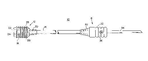
Fig. 1 is a side elevational view of a unitary ECG monitor
lead and needle electrode system according to this invention;
Fig. 2 is a perspective view of the ECG junction connector
of Fig.1;
Fig. 3 is a side elevational view with the needle shown in
cross section of the needle electrode unit of Fig. l;
Fig. 4 i5 an enlarged cro6s-sectional side elevational view
of the needle electrode unit of Fig. 1 shown with a hollow needle
electrode; and
Fig. 5 is a schematic block diagram of a plurality of
unitary ECG monitor leads and needle electrode systems connected
to an ECG monitor and junction.
This invention may be accomplished using a unitary ECG
monitor lead and needle electrode system which includes a
connector for connection to an ECG monitor junction. Typically
the connector is an injection-molded plastic element made of
polyethylene or some other suitable plastic and includes a body
portion and a strain relief portion integrally connected with a
lead. The lead may be shielded or unshielded. The other end of
the lead, typically six feet long in the environment of ECG
monitors, is connected with a needle electrode unit. The needle
electrode unit includes a body portion
which receives the lead integrally at one end and at the other
end recéives the electrode needle to form a single integral unit.
The signal conductor of the lead is electrically connected with
the electrode needle inside of the body portion, and if the lead
is a shielded lead the shield terminates within that body
portion. The needle electrode itself may be hollow or solid.
There is shown in Fig. 1 a unitary ECG monitor lead and
needle electrode system 10 according to this invention which
includes a connector 12 for connection to an ECG monitor junction
box, a lead 14 typically up to six feet in length, and a needle
electrode unit 16. Connector 12 is typically an injection molded
plastic such as polyethylene or the like which has a ribbed body
portion 18 and a strain relief portion 20. There are two female


f . ~ 1

2 0 5 5 9 4 3 ~

Replacement Page 4
sockets 22 and 24, Fig. 2, at the end of connector 12 which
electrically interconnect with a shield 26 and signal conductor
2~, respectively, of lead 14. Lead 14 may be typically coated
with a plastic jacket SUCll as polyethylene or polyurethane.
Needle electrode unit 16 at the other end of lead 14 is also made
of an injection molded plastic and includes a strain relief area
30 and a body portion 32, Fig. 3. Electrode needle 34 is solid
and is integral with an extends outwardly from body portion 32.
If lead 14 were an unshielded cable, female socket 22 would be
eliminated. Body 32 may include a replacement indicator 36
bearing a legend such as "RA" which indicates "right arm" for the
placement of the needle electrode 34.
Needle electrode unit 16 is shown in greater detail in Fig.
4, where shield 26 can be seen as termin~ting within body portion
32 and signal conductor 28 can be seen to electrically connect
with needle electrode 34. As shown in ~ic~ , needle electrode
34 is hollow having a tubular bore 36 tl~rough its central portion
similar to conventional hypodermic needles, but electrode needle
34 does not include the usual luer hub
A plurality of unitary ECG monitor lead and needle electrode
systems lOa, lOb and lOc, Fig. 5, according to this invention are
typically employed by plugging into a junction 50 which is
intérconnected by a cable system 52 to a conventional ECG monitor
54. Cable system 52 includes a conventional cable 56 with end
connectors 5~ and 60. Junction box 50, typically includes three
single pins or three pairs of pins in the case of shielded leads
for receiving the connectors 12a, 12b and l2c of unitary ECG
monitor lead and needle electrode systems IOa, lOb and lOc. If
junction SO is disposed in the ECG monitor itself, cable system
52 can be eliminated.
Although specific features of this invention are shown in
some drawings and not others, this is for convenience only as
feature may be combined with any or all of the other features in
accordance with the invention.
Other embodiments will occur to those skilled in the art and
are within the following claims:


W0 95/17026 PCr/US94/11287
21SS94~


What is claimed is:

Representative Drawing
A single figure which represents the drawing illustrating the invention.
Administrative Status

For a clearer understanding of the status of the application/patent presented on this page, the site Disclaimer , as well as the definitions for Patent , Administrative Status , Maintenance Fee  and Payment History  should be consulted.

Administrative Status

Title Date
Forecasted Issue Date 1998-04-07
(86) PCT Filing Date 1994-10-06
(87) PCT Publication Date 1995-06-22
(85) National Entry 1995-08-11
Examination Requested 1995-08-11
(45) Issued 1998-04-07
Deemed Expired 1999-10-06

Abandonment History

There is no abandonment history.

Payment History

Fee Type Anniversary Year Due Date Amount Paid Paid Date
Application Fee $0.00 1995-08-11
Registration of a document - section 124 $0.00 1995-11-02
Maintenance Fee - Application - New Act 2 1996-10-07 $100.00 1996-07-31
Maintenance Fee - Application - New Act 3 1997-10-06 $100.00 1997-09-22
Final Fee $300.00 1997-11-14
Owners on Record

Note: Records showing the ownership history in alphabetical order.

Current Owners on Record
PLC MEDICAL SYSTEMS, INC.
Past Owners on Record
LASER ENGINEERING, INC.
LINHARES, STEPHEN J.
NEGUS, CHARLES C.
RUDKO, ROBERT I.
Past Owners that do not appear in the "Owners on Record" listing will appear in other documentation within the application.
Documents

To view selected files, please enter reCAPTCHA code :


To view images, click a link in the Document Description column. To download the documents, select one or more checkboxes in the first column and then click the "Download Selected in PDF format (Zip Archive)" or the "Download Selected as Single PDF" button.

List of published and non-published patent-specific documents on the CPD .

If you have any difficulty accessing content, you can call the Client Service Centre at 1-866-997-1936 or send them an e-mail at CIPO Client Service Centre.


Document
Description 
Date
(yyyy-mm-dd) 
Number of pages   Size of Image (KB) 
Cover Page 1996-01-18 1 17
Cover Page 1998-04-06 1 40
Claims 1997-09-15 2 42
Representative Drawing 1998-04-06 1 4
Abstract 1995-06-22 1 41
Claims 1995-06-22 3 39
Description 1995-06-22 4 218
Drawings 1995-06-22 3 45
Description 1997-09-15 5 207
Correspondence 1997-11-14 1 32
National Entry Request 1995-10-31 3 88
National Entry Request 1995-10-02 1 44
National Entry Request 1995-08-11 5 144
Prosecution Correspondence 1995-08-11 9 408
International Preliminary Examination Report 1995-08-11 1 48
Prosecution Correspondence 1997-08-21 1 33
Examiner Requisition 1997-08-01 2 37
Office Letter 1995-10-03 1 21
Fees 1996-07-31 1 43