Note: Descriptions are shown in the official language in which they were submitted.
21 ~ P~;~f~~ ~ ~.
618
1 "Limb Protector"
2
3 This invention relates to a limb protector,
4 particularly a protector for a jointed limb, that is a
knee or elbow protector.
6
7 Injuries to limbs and to joints occur for several
8 reasons, including participation in contact sports such
9 as American football or ice hockey, in individual
sports such as skiing or motor cycle racing, or indeed
11 any active sport. In addition, injuries to limbs and
12 joints occur in active occupations such as the police
13 or armed forces, or in any type of accident.
14
After an injury occurs, the limb or joint affected by a
16 minor injury is conventionally supported by elastic
17 supports which give slight restriction of movement or
18 by rigid splints for major injuries, giving complete
19 immobilization.
21 In some cases, preventative equipment if available.
22 Hinged knee braces (de-rotational braces) are available
23 to prevent twisting of a knee, and can be worn during
24 activities such as skiing, but by their nature are
21~61~~
1 restrictive, the hinges permit only forward bending.
2 Braces are available for sports such as American
3 football which protect the knee against side impact, or
4 frontal impact, but also restrict movement,
(prophylactic or preventive braces). Dynamic braces
6 are also available, with eccentrically placed hinges to
7 provide protection to torn ligaments.
8
9 In more extreme form, riot police can wear body armour.
In a different sphere, the medical profession use light
11 weight splints to give complete immobilization of a
12 knee or elbow when rotational movement is likely to
13 cause damage, especially for use in accidents to permit
14 safe transport of the_person to hospital.
16 In many cases, a small amount of movement of the
17 affected joint might be beneficial to healing, and
18 indeed speed recovery, but existing equipment allows
19 either relatively large twisting movements, as with
elastic supports, or no twisting movement, as with
21 hinged braces.
22
23 In the application by.Fratesi, WO 91/01701, separate
24 knee and thigh guards are connected by a hinge at the
knee joint, but the.wearer's knee can move only by
26 bending in the vertical plane.
27
28 In Offenlegungschnift DE 3905837, K and K Inc, a
29 three-part knee~protector is hinged at upper and lower
hinging points, but the wearer's knee can move only by
31 bending in the vertical plane.
32
33 ~ In US Patent No 4,884,567., a knee brace is hinged at a
34 single pivot point, and the wearer's knee can move only
by bending in the vertical plane.
36
37 The current invention provides a broader range of
38 facilities than any existing brace, and can be used in
39 prophylactic, dynamic, or de-rotational mode.
A~NEI~Jt?ED SNE~T
C: \liSiI\SPECS\P12958 . AlfE
~,, _ 21~~I~~ 3
1 According to the invention a limb protector comprises
2 an upper rigid curved support; a lower rigid curved
3 support; and means for permitting relative rotation of
4 the upper support and the lower support, such relative
movement taking place in a plane substantially parallel
6 to the planes of curvature of the upper and lower
7 supports. Preferably the amount of relative rotation
8 is adjustable. Preferably there is also provided means
9 for permitting relative hinging of the upper and lower
l0 supports in a plane orthogonal to the plane of relative
11 rotation.
12
13 In use the upper rigid curved support~is placed around
14 the upper part of a limb, such as a thigh or upper arm,
and the lower rigid curved support is placed around the
16 lower part of a limb, such as a lower leg or forearm.
17 The means permitting relative hinge of the supports
18 permits the knee or elbow to bend in a plane which in
19 the case of the knee will be substantially vertical
with the relative rotation being in a substantially
21 horizontal plane, permitting the knee to twist, to a
22 degree which can be preset.
23
24 Preferably, either the upper or the lower rigid curved
support is provided.in two-part form with a sliding
26 joint between the parts so as to permit relative
27 rotation of the upper and lower supports. In the case
28 of a knee protector, the sliding joint is provided in
29 the lower support adjacent to the upper support,
preferably arranged so that relative rotation occurs
31 immediately below the knee.
32
33 ~ Preferably there is also provided a rigid curved direct
34 impact protector which overlaps the lower portion of
the upper support and the upper portion of the lower
36 support. The direct impact protector protects a knee
37 joint from front impact and an elbow joint from rear
38 impact.
39
p~!~~~'yC~0 SHE~C
C:\I~MI\9PECS\P1295l.AlIE
~,, ~~~~~~~ 3A
1 The impact protector also acts as a hinge cover by
2 overlapping the adjacent edges of the upper and lower
3 supports during a hinging movement. The cover may be
4 in two parts, pivotally connected to each other and one
part being pivotally connected to each of the upper and
6 lower supports.
7
8 Optionally there is further provided at least one
9 rigid side impact protector, overlapping the lower
l0 portion of the upper support and the upper portion of
11 the lower support and positioned to protect a joint
12 within the supports from side impact.
13
14 - Preferably the rigid material of which the curved
supports are made is resistant material such as carbon-
16 fibre reinforced plastics material.
17
18 The invention will now be described by way of example
19 only with reference to the accompanying drawings in
which:
21
r~~c;.~C;~;: SHC~'
c:\Tt'AI\SPECS\P1295l.AriE
~., 21~618a r~~:
4
1 Figure 1 is an exploded view of a knee protector
2 according to the invention;
3
4 Figure 2 is a detailed view of part of Figure 1
illustrat ing the relative rotation of the upper
6 and lower limb supports at the front of the
7 support;
8
9 Figure 3 is a detailed view of part of Figure 2;
11 Figure 4 is a detailed view of a further part of
12 Figure 1 illustrating the relative rotation of
the
13 upper and lower limb supports at the rear of the
14 support;
16 Figure 5 is a view of an assembled, alternative
17 embodimen t of a knee protector according to the
18 invention ;
19
Figure 6 is an example of an adjustable fastening
21 mechanism for a limb protector;
22
23 Figure 7 is an example of means for adjusting the
24 size of a knee protector for width fitting;
26 Figure 8 illustrates means for allowing hinging
27 movement;
28
29 Figure 9 is an example of a wall material;
31 Figure 10 illustrates the knee protection of
32 Figure 1 in assembled form;
33
34 Figure ll illustrates how hinging action allows
the protector
to be put
on a human
knee;
~:~ . ~,. ~.:
1 Figure 12 illustrates a variation of the protector
2 of Figured ;
3
4 Figure 13 illustrates the protector of Figure 1
5 from in front and from the rear;
6
7 Figure 14 is a variation of the protector
8 illustrated in Figure 1;
9
Figure 15 is a view of the inside of the Figure 14
11 embodiment;
12
13 Figure 16 shows the assembly of the Figure 1
14 variation;
16 Figure 17 illustrates a variation of Figure 14.
17
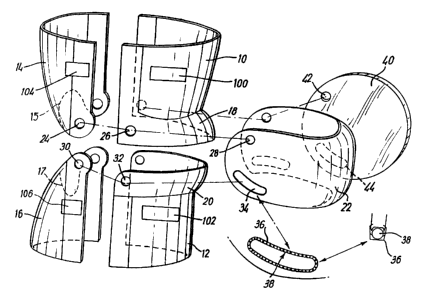
18 In Figure 1 a knee protector comprises an upper frontal
19 leg support 10, a lower frontal.leg support 12, an
2o upper rear leg support 14 and a lower rear leg support
21 16. Each leg support 10,/ 12, 14, 16 is curved to fit a
22 human leg (not shown) and conveniently made of rigid
23 but resilient material. Each leg support may be of
24 greater length in the vertical direction than
illustrated, to~give increased leg support and
26 protection.
27
28 The lower part of upper frontal leg support 10 and the
29 upper part of lower frontal leg support 12 are provided
with extensions 18, 20 respectively of gradually
31 increasing curvature, or skirt-shaped parts, to
32 accommodate the human kneecap. The gap between the
33 edges of the extensions 18, 20 is covered by a curved
34 knee protector 22 which extends around the upper and
lower frontal supports.
P~T/GB 94/003~~
21~~1~~
6
1 The knee protector protects the knee from impacts from
2 the front, and the overall arrangement prevents the
3 knee from being pushed backwards, as the upper and
4 lower supports distribute the impact to the tibia and
fibia.
6
7 The leg supports 10, 12; 14, 16 and the knee protector
8 22 are connected together to allow the knee joint to
9 bend in a vertical plane, ie to bend normally.
Conveniently this is achieved by connecting studs (not
11 shown) which pass through apertures in the
12 aforementioned parts. For example, one stud could pass
13 through the circular aperture 24 in upper rear support
14 14, circular aperture 26 in upper frontal support 10
and circular aperture'28~in the side upper part of knee
16 protector 22. Another~stud could pass through circular
17 aperture 30 in lower rear support 16, circular aperture
18 32 in lower frontal support 12 and kidney-shaped
19 aperture 34 in the side, lower part of knee protector
22.
21
22 A similar arrangement of apertures and studs is
23 provided on the side of the protector distant from the
24 direction of viewing.
26 Such an arrangement will allow normal bending of the
27 knee, with the stud moving along kidney-shaped aperture
28 34. Preferably this aperture is provided with ball
29 bearings in a retaining channel, as shown by references
36, 38 in the partial enlargement.
31
32 There is also provided a circular side impact protector
33 40, of rigid, resilient material provided with an
34 upper circular aperture 42 and a lower kidney-shaped
aperture 44 through which studs can pass as through
P~.'~I~~ ~ ~ ~ ~~ '~~
21~~1~5
7
1 corresponding apertures in the side of the protector
2 distant from the direction of viewing. The studs would
3 hold the side impact protector 40 in such a position as
4 to protect the knee from side impact.
6 The lower edge of upper rear support 14 and the upper
7 edge of lower rear support 16 are provided with
8 approximately semi-circular cutouts, 15, 17 indicated
9 by dotted lines, which allows added room for the foot
and the leg to pass through the unit, so that the unit
il can be placed over the knee .
12
13 Figure 2 shows upper and lower frontal supports 10, 12
14 as in Figure 1, and also an enlargement of part of
lower support 12, and shows a left leg knee protector,
16 in which the lower support 12 rotates anticlockwise
17 with respect to the upper support 20. The upper support
18 10 is always held rigid because it is attached to the
19 thigh.
21 The hinging points to connect the supports l0, 12, 14,
22 and 16 are in a slightly different arrangemant from
23 those in Fig. 1.
24
The extension 20 is shown separated from the support
26 12, to illustrate clearly the predeterminable relative
27 rotation of the two parts.
28
29 The upper edge of support 12 ~is formed as a J-shaped
channel 46, of narrow bore 48 from the rear of the
31 support towards the front, and of broader bore 50
32 around the front and to the rear of the support on the
33 side distant from the viewer.
34
The change of bore diameter occurs on the protector at
. .. ~ ~_rE ~ ~ ~ ,~~ ~°~~ ~tu~, 26
"_''! ~.., ___ _, _ - ..
215618
8
1 a position corresponding to the inside of the human
2 knee within it, and at an angle of about 45° in a
3 horizontal plane from the front of the knee.
4
Within the br-oader bore 50 adjacent the change to
6 narrow bore 48 is a spring spacer (washer) 52, shown
7 also in a partial, enlarged view.
8
9 The extension 20 carries on its lower edge a J-shaped
protrusion 54 having a narrow diameter part 56 and a
11 broader diameter part 58.
12
13 Figure 3 illustrates in section the J-shaped channel 46
14 and the J-shaped protrusion 54.
16 Referring once more to Figure 2, the narrow end of 54
17 is inserted into the broad end of the channel 46 and
18 the extension 20 is rotated clockwise relative to
19 support 12 until it is in the same position in rotation
relative to general support 12 as in the Figure.
21 Further rotation is impossible because the broader
22 diameter part 58 of protrusion 54 cannot enter the
23 narrow bore part 48 of channel 46. The narrow diameter
24 part 56 of J-protrusion 54 can however pass through the
spring spacer 52, but the spring spacer 52 itself
26 cannot enter the narrow bore channel 48.
27
28 When there is human knee within the protector, relative
29 movement of the J-protrusion 54 in J-channel 46 permits
the knee to rotate in a substantially horizontal plane.
31 The maximum rotation permitted by the protector will be
32 45°.
33
34 It is sometimes advantageous to limit such rotation,
when for example the knee has been injured, or when the
PC~IG~ ~ 4 l ~ ~'
X156185
9
1 natural rotation of the knee is less than 45°. The
2 permitted rotation can be set to the individual
3 requirement of the person wearing the protector by
4 adjusting the spring spacer 52 which can be held in
position by placing a screw stud (not shown) through
6 the broad bore part 50 of channel 46. This locks the
7 spacer 52 in position and effectively increases the
8 length of the narrower bore channel 48, and therefore
9 limits rotational movement of J-shaped protrusion 54.
11
12 The movement is the same as that of a human leg. If
13 the knee is bent, the lower part of the leg (tibia) can
14 be rotated while the upper part (thigh) is completely
immobile. The stop 60 prevents the lower support from
16 moving in the wrong direction, the lower right leg when
17 bent does not rotate anticlockwise, lower left leg when
18 bent does not rotate clockwise. Figure 2 shows a left
19 knee protector, so the lower support 12 rotates
anticlockwise in the same direction as the lower leg,
21 and away from the stop 60. The stop 60 prevents
22 movement of the lower support 12 inwards or clockwise,
23 from the central position in.which the edges of
24 supports 20 and 12 are in line, as~in the~Figure.
26 Figure 4 illustrates the arrangement which permits
27 relative rotation of the upper and lower
rear supports
28 14, 16. The lower support 16 has two upper,
separable
29 portions 62, 64, one on either side and
each having an
aperture 36, 66, for a stud (not shown).
31
32 The upper edges of the support 16 adjacent the
33 separable portions 62, 64 carry respective J-shaped
34 channels 66, 68 and the lower edges of the separable
portions 62, 64 carry J-shaped protrusions 70, 72. The
PG~I~B ~° 4. .
f ~ J I':y~..~:,
X15618
1 J-protrusions run within the J-channels, as described
2 with reference to Figures 2 and 3.
3
4 The limitation of rotation is however predetermined
5 solely by the frontal supports as illustrated in Figure
6 2.
7
8 Figure 5 illustrates the frontal supports of a
9 different embodiment of a knee protector having
10 further, optional features.
v
11
12 The protector comprises upper and lower frontal
13 supports 80, 82 and a knee protector indicated
14 generally at 84 which is formed by two overlapping
parts 86, 88 hinged at 90, 92 to the upper and lower
16 supports 80, 82 respectively. The two parts of the
17 knee protector are hinged to each other at 94. Similar
18 hinges are provided at the side of the protector remote
19 from the viewer. The arrangement is such that the
overlapping parts 86, 88 overlap by a varying amount in
21 use, limited by the width of the sections 86 and 88.
22 This gives the wearer greater mobility [in bending the
23 knee] than the embodiment shown previously.
24
A side impact protector, 96, shown spaced from the
26 protector, may be hinged to the knee protector at
27 hinges 94 and 92.
28
29 Optionally, there can be placed within the knee
protector a spacer 97 (shown largely by the dotted
31 line) of resilient, friction-free material. The spacer
32 can be fixed to the knee protector 94 at such a
33 position that it cushions the anterior cruciate
34 ligament of the knee. The spacer 97 can be of selected
thickness, and such a spacer can be provided at each
._ _ . .
L ~ l-., t L tn ~-..w.. _
~1~~~.~~
11
1 side of the knee to give a very close fit of the knee
2 protector, giving good support of the anterior cruciate
3 ligament.
4
such spacers can also be used with the embodiment of
6 Figure 1, and in addition to ligament support can be
7 used to give close fit of a protector to a knee.
8
9 It is an advantage of a limb protector according to the
invention that it can be individually adjusted to suit
11 the joint it contains. For example, it may be
12 manufactured in a number of basic sizes, which can be
13 adjusted to fit the individual limb within it.
14
Referring again to Figure 1, the frontal and rear
16 supports may be fastened together by adjustable means,
17 indicated schematically by the rectangles references
18 100, 102, 104, 106.
19
The relative spacing of the frontal and rear supports
21 can be individually varied to give a good fit.
22
23 Preferably the adjustable means as such that the
24 adjustment can be preset, and subsequent removal and
replacement of the protector can be relatively rapid
26 and simple.
27
28 An example of such an adjustable means is shown in
29 Figure 6. Figure 6(a) shows a ratchet 108 within a
cover 110 which is spring loaded to prevent exposure of
31 the ratchet and which retreats as the ratchet moves.
32 There is a locking mechanism with a ring pull 114.
33
34 Figure 6(b) shows an end view of Figure 6(a). Below
. the ring pull 114 there is a piston type mechanism 116
r4naa ~ ~ ~ a a
~1~~~~~
12
1 having an inverted T-shaped gap 118; when the ring pull
2 is pulled, the gap 118 allows the ratchet 108 to run
3 free within the cover 110. As spring retainer 120
4 returns the smaller gap of the inverted T-shape, which
is shaped like a sawtooth so that when it is released]
6 fits perfectly between the ratchet teeth, prevents the
7 ratchet from moving back and forth, thus lacking the
8 ratchet in place.
9
The ratchet can therefore be adjusted to give the
11 required separation of the frontal and rear supports
12 for an individual leg. A torsion spring 112 then
13 allows minimal expansion of the ratchet, to correspond
14 to muscular expansion of the leg.
16 In Figure 7, a method of adjusting the size of a knee
17 protector is illustrated. The upper frontal support l0
18 is formed in two parts 10(a) and 10(b) with a vertical
19 overlap 10(c). The overlap on part 10(b) has two
series of vertically-separated perforations, 124. The
21 overlap on part 10(a) has a series of projecting studs
22 122 at the same distance as the perforations, and
23 having right-angle ends which can enter the
24 perforations. The amount of overlap is therefore
adjustable, eg by 2 cm, and the size~of the support 10
26 can be selected as appropriate.
27
28 Figure 8 illustrates one of the studs which hinge the
29 upper and lower, frontal and rear supports together.
The stud 126 passes through the thickness of, for
31 example, the lower rear support 16, lower frontal
32 support 12, and knee protector 22. The head of the
33 stud is protected by a cover cap 128 which is bullet-
34 shaped to allow easy access of a split pin which is
sandwiched between a spring washer 132 and a plain
. f!~~ ~ c ~~ ., '. ~ c f ,ec. ". .. ~, s
i 0I a ~ ~ 1,/ y ~r '' N ;, 7
~1~~~~~
13
1 washer 134. The cover cap 128 is screwed into the top
2 of the stud 126 and is prevented from coming undone by
3 the spring washer 132.
4
Figure 9 shows that any of the supports or knee
6 protector can be made of a sandwich construction 136.
7 Either in the inside of the sandwich contains a
8 corrugated impact-absorbing material 138, or some other
9 material is used that has relevant absorbtion
coefficients.
11
12 Figure l0 shows in assembled form a knee protector as
13 illustrated in Figures 1 and 2. Supports 10, 12, 14,
14 i6 and knee protector 22 are shown in their operative
positions, together with side impact protector 41.
16 Figure 11 shows how the same parts can be hinged to
17 allow a wearer to place it on a knee, or remove it.
18 Figure 12 shows a variation of a knee protector in
19 which the upper and lower frontal supports 10(a), 12(a)
are extended to give improved protection to the thigh
21 and shin.
22
23 In Figure 13, 13(a) is a view from the front of a knee
24 protector and 13 (b) is a view from the rear of a knee
protector. In Figure 13(a), the side impact protectors
26 40, 41 are connected to the knee protector 22 and other
27 parts of the protector by studs 126. As will be seen,
28 there are spacers 140 between the knee protector 22 and
29 the side impact protectors 40, 41. There are also
absorption pads 142 to take pressure from the side
31 impact protectors 40, 41 when force is applied to them,
32 to help distribute the impact force throughout the
33 whole protector unit.
34
Figure 13(b) also shows cutaway sections on the upper
a ~
zi~6i~~
14
1 and lower rear supports which allow the wearers foot to
2 pass through when the rear supports are hinged open as
3 shown in Figure 11.
4
Figure 13(b) also illustrates the attachment points
6 146, 148 for an adjustable padded torsion bar (not
7 shown) which can be locked to the protector behind the
8 knee. This allows the protector to be used as a light
9 weight temporary splint.
to
11 A joint protector according to the invention allows
12 free hinging of a joint such as a knee in the normal
13 way, and predetermined rotational movement. In some
14 circumstances however it may be advantageous to prevent
rotational movement.
16
17 Referring again to Figure 2, the main part of lower
18 frontal support 12 carries an L-shaped projection 150
19 the female part of a coupling.
21 Figure 14 shows a two-part knee protector as in Figure
22 5. Part 88 carries a male part of a coupling, 152 in
23 ~ the form of a square section rod. If the two parts of
24 the coupling fit together, rotation of the protector is
prevented. The two parts will be brought into this
26 position when the wearer of the knee protector stands
27 with a straight leg, and will uncouple when the wearer
28 bends the knee. The lock thus works in a parallel way
29 to the human leg.
_
31 Figure 15 is a view of a two-part knee protector from
32 inside, showing the two parts 86, 88, the hinge-points
33 90, 92, removable spacer 97 to protect the anterior
34 cruciate ligament, and side impact protector 96 with
its hinge points.
PC~I~~ ~ ~ ~ ~~ ~
7
1 Figure 16 is a schematic view of the protector of
2 Figure 5, illustrating the hinge unit 94 which holds
3 the two parts 86, 88, of the knee protector together.
4
5 Figure 17 illustrates a variation of the knee protector
6 shown in Figures 14 and 15, with the size adjustment
7 ~ device shown in Figure 7. The knee protector 140 has
8 two overlapping part 142, 144, hinged together at hinge
9 point 146 which has 3 hinge positions to allow
10 adjustment to fit an individual knee.
11
12 While the parts of the knee protector have been
13 referred to as rigid, it is preferable to use a
14 resilient material which by nature has impact-absorbing
15 properties. Such a material is carbon fibre composite
16 material.
17
18 The spacers 97 are conveniently made of a softer
19 material with relevant absorption coefficients, such as
polypropylene.
21
22 The inside of~the knee protector may be line with a
23 padding of stretch, anti-friction material, which may
24 also extend to the insides of the upper and lower
frontal supports. Such a lining allows the protector
26 to move smoothly over the knee and helps to prevent
27 pinching or damage to the kneecap.
28
29 The invention has been described with reference to a
knee protector, it is also applicable to an elbow
31 protector.
32
_ . .. .~.:,.
~a ..a : a s.~i~ ~ ~: ~ i~