Note: Descriptions are shown in the official language in which they were submitted.
CA 02156222 2005-O1-20
79832-19
1
Technical Field
The present invention relates generally to the trailer towing
field and, more particularly, to a new and improved hitch bar
including an integrally cast post and mounting rack of ductile iron
for utilization in a trailer hitch assembly.
Background of the Invention
It has long been known in the art to provide a trailer hitch
assembly for towing a trailer behind a vehicle incorporating (a) a
hitch bar receiver connected by a frame to the vehicle, (b) a hitch
bar including a mounting rack or support and a post adapted for
engagement in the receiver and (c) a ball mount head adapted for
engagement on the mounting rack. This basic type of trailer hitch
assembly is shown in, for example, U.S. Patents 3,482,856 to Reese;
3,768,837 to Reese; 4,033,601 to Lindahl et al. and
U.S. patent Serial No. 5,375,867 filed October 15, 1993
entitled "Weight Distributing Hitch" also own by the assignee of
the present invention.
In the over thirty years since this basic type of trailer
hitch assembly was developed, numerous design modifications have
been made with a goal of improving the overall product. For
example, competitive pressures in the marketplace have led the
2~~~~~~
2
various manufacturers of trailer hitch assemblies to make a serious
effort to control and reduce manufacturing costs while at the same
time increasing the overall towing capacity of the assemblies to
benefit the end user. While significant improvements have been
made, these competitive pressures are still present and still
further improvements relating to the control of costs and the
enhancement of performance characteristics are desired.
Summary of the Invention
Accordingly, it is a primary object of the present invention
to provide a trailer hitch assembly of relatively simple
construction that may be produced at a lower overall cost by means
of casting a hitch bar for such an assembly from a strong material
such as steel, graphite composite and relatively inexpensive
ductile iron.
Another object of the present invention is to provide a hitch
bar of improved design that is not only relatively inexpensive to
produce but also of significantly reduced weight when compared to
conventional rolled steel and forged hitch bars of similar towing
capacity. Advantageously, the reduction in weight allows an
individual to more conveniently manipulate the hitch bar so that it
is easier to engage in and withdraw from the hitch receiver mounted
to the intended towing vehicle.
Still another object of the present invention is to provide a
hitch bar of inexpensive construction and reduced overall weight
that also provides the seemingly conflicting benefit of
significantly increased towing capacity so as to allow the
CA 02156222 2005-O1-20
79832-19
3
efficient and effective towing of larger, heavier trailers than
possible with hitch bars of similar size and/or weight constructed
in accordance with conventional manufacturing approaches.
Yet another object of this invention is to provide a new and
simple method of manufacturing an integral, one-piece hitch bar
from cast material. Additional objects, advantages and other
novel features of the invention will be set forth in part in the
description that follows and in part will become apparent to those
skilled in the art upon examination of the following or may be
learned with the practice of the invention.
To achieve the foregoing and other objects, and in
accordance with the purposes of the present invention as described
herein, an improved hitch bar is provided for utilization in a
trailer hitch assembly of the type just described in the background
section of this document. The hitch bar is an integral post and
mounting rack cast from a material selected from a group including
steel, graphite composite and ductile iron. Such a one-piece,
integrally cast hitch bar provides a strong, unitized construction
from material exhibiting the necessary strength and other desirable
physical characteristics as are required to result in significant
increases in towing capacity over prior art hitch bars of similar
size and shape fabricated from cold rolled and forged steel
components.
In the most preferred embodiment ductile iron is utilized in
21~~~~~
4
the integral casting of the hitch bar. This ductile iron is
characterized by rounded or spheroidal graphite in a ferritic,
pearlitic or ferritic-pearlitic matrix. Most preferably the
ductile iron has a composition consisting essentially of 3.2-4.1%
carbon, 1.8-3.0% silicon, 0.1-1.0% manganese, 0.015-0.1%
phosphorous, 0.005-0.035% sulfur, up to 2.0% copper and the balance
iron and residuals including but not limited to magnesium and
cerium. Depending upon the specific chemical composition selected,
the casting may be utilized in the "as cast" condition for many
applications. This is advantageous from the standpoint of lowering
production costs. The cast ductile iron, as cast, is further
characterized by a minimum tensile strength of 65,000 psi, a
minimum yield strength of 45,000 psi and an elongation for two inch
length of between 6-12%.
Where additional strength is required, the cast ductile iron
hitch bar may be annealed or austempered to further improve the
physical properties of the integrally cast hitch bar. For example,
an austempered hitch bar cast from ductile iron may be further
characterized by a 30 Rockwell C hardness and a minimum tensile
strength of between 120,000-150,000 psi. In the most preferred
embodiment, the cast ductile iron alloy utilized is SAE grades
D4512 or D5506.
Advantageously, the present invention not only allows for a
significant increase in towing capacity but the casting of the
hitch bar from ductile iron significantly lowers production costs
compared to the prior art approach of fabricating the hitch bar
from a cold rolled steel post and forged mounting rack. Still
21~~~~
further, the overall weight of the hitch bar may be significantly
reduced when compared to a hitch bar of prior art design providing
similar strength and hence towing capacity. This is not only
achieved by the superior physical characteristics of the cast
ductile iron used for the hitch bar but also by the manner in which
it is cast. More specifically, the front face of the mounting rack
of the hitch bar is formed so as to include a midline channel.
This channel defines a pair of parallel projecting wings. The
mounting rack further includes a series of aligned mounting
apertures extending through the wings. These apertures are also in
communication with and extend substantially perpendicular to the
midline channel. Such a construction provides sufficient strength
and integrity for towing a vehicle while also significantly
reducing material requirements and the overall mass of the hitch
bar.
Additional reductions in mass without any appreciable loss in
strength may also be provided. More specifically, the post of the
hitch bar includes upper, lower, left side, and right side faces.
Face cavities are recessed within margins of the left side and
right side faces so as to form a substantially I-beam structure in
cross section. Of course, such recesses eliminate the weight of
material that would otherwise be present thereby further reducing
the overall mass of the hitch bar. It should be realized, however,
that the structural strength and integrity of the hitch bar are not
compromised due to the presence of the full width margins that
result in the I-beam cross section. Further, the anchoring
aperture that is provided in the post to receive a pin for securing
CA 02156222 2005-O1-20
79832-19
6
the hitch bar in the hitch receiver is positioned in a
reinforced section having a lateral dimension corresponding
to the full dimensions of the margins rather than the
recessed portions. Thus, added strength is provided.
In accordance with still another aspect of the
present invention, there is provided a method of
manufacturing a hitch bar of the type described for a
trailer hitch assembly. Briefly describing the method, it
comprises the casting of the hitch bar so as to include an
integral post and mounting rack of steel, graphite composite
or ductile iron and the machining of the cast hitch bar to
remove drafted surfaces. The method further includes the
cast forming of the midline channel and face recesses in the
mounting rack and post respectively that reduce the overall
mass of the hitch bar to allow it to be more easily carried
and manipulated by an operator when preparing a vehicle for
towing. Preferably ductile iron is utilized in the casting.
The method may then further include a step of austempering
the cast ductile iron hitch bar so as to provide additional
desired physical properties including a 30 Rockwell C
hardness and a minimum tensile strength of between
120,000-150,000 psi.
According to a broad aspect of the invention,
there is provided a hitch bar for a trailer hitch assembly,
comprising: an integral post and mounting rack cast from
ductile iron; and wherein said post includes at least one
cavity on mutually opposed side faces so as to form a
substantially I-beam cross section.
According to another broad aspect of the
invention, there is provided a hitch bar for a trailer hitch
assembly, said hitch bar comprising: an integral post and
CA 02156222 2005-O1-20
79832-19
6a
mounting rack cast from ductile iron characterized by
rounded graphite in a matrix structure selected from a group
consisting of a ferritic matrix, pearlitic matrix and
mixtures thereof and said ductile iron having a composition
consisting essentially of 2.0-4.5o carbon, 0.75-4.0~
silicon, up to 2.0~ manganese, up to 0.3~ phosphorous, up to
0.3o sulfur, up to 2.0~ copper, the balance iron; and
wherein said post includes at least one cavity on mutually
opposed side faces so as to form a substantially I-beam
cross section.
According to a further broad aspect of the
invention, there is provided a method of manufacturing a
hitch bar for a trailer hitch assembly, comprising: casting
the hitch bar so as to include an integral post and mounting
rack of ductile iron; and machining said cast hitch bar to
create at least one cavity on mutually opposed side faces of
said post so that said post forms a substantially I-beam
cross section.
According to a still further broad aspect of the
invention, there is provided a hitch bar for a trailer hitch
assembly, comprising: an integral post and mounting rack
cast from one material; and wherein said post includes at
least one cavity on mutually opposed side faces so as to
form a substantially I-beam cross section.
According to yet another broad aspect of the
invention, there is provided a method of manufacturing a
hitch bar for a trailer hitch assembly, comprising: casting
the hitch bar so as to include an integral post and mounting
rack of one material; and machining said cast hitch bar to
create at least one cavity on mutually opposed side faces of
said post so that said post forms a substantially I-beam
cross section.
CA 02156222 2005-O1-20
79832-19
6b
Still other objects of the present invention will
become apparent to those skilled in this art from the
following description wherein there is shown and described a
preferred embodiment of this invention, simply by way of
illustration of one of the modes best suited to carry out
the invention. As it will be realized, the invention is
capable of other different embodiments and its several
details are capable of modification in various,
2:~~~~,~~
obvious aspects all without departing from the invention.
Accordingly, the drawings and descriptions will be regarded as
illustrative in nature and not as restrictive.
Brief Description of the Drawings
The accompanying drawing incorporated in and forming a part of
the specification, illustrates several aspects of the present
invention and together with the description serves to explain the
principles of the invention. In the drawing:
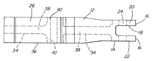
Figure 1 is a right side elevational view showing the cast
hitch bar of the present invention:
Figure 2 is a top plan view of the hitch bar shown in figure
1: and
Figure 3 is a sectional view of the hitch bar taken along line
3-3 as shown in figure 1.
Reference will now be made in detail to the present preferred
embodiment of the invention, an example of which is illustrated in
the accompanying drawing.
Detailed Description of the Invention
Reference is now made to the drawing figures showing the
improved hitch bar 10 of the present invention of unitized, cast
construction. Such a hitch bar 10 is adapted for utilization in a
trailer hitch assembly of the type previously described wherein a
bar or post portion is received and held by a pin in a hitch
receiver mounted to a towing vehicle and a mounting rack or
support portion receives a head assembly for holding a ball mount
8
upon which the trailer may be attached.
More particularly, the hitch bar 10 includes an integral post
12 and mounting rack 14 cast, for example, from steel, graphite
composite or ductile iron. Preferably ductile iron is utilized.
The ductile iron is characterized by rounded or ball-like graphite
in a matrix structure selected from a group consisting of a
ferritic matrix, pearlitic matrix or a ferritic-pearlitic matrix
mixture. Further, the ductile iron preferably has a composition
consisting essentially of 2.0-4.5% and more preferably 3.2-4.1%
carbon, 0.75-4.0% and more preferably 1.8-3.0% silicon, up to 2.0%
and more preferably 0.1-1.0% manganese, up to 0.3% and more
preferably 0.015-0.1% phosphorous, up to 0.3% and more preferably
0.005-0.035% sulfur, up to 2.0% copper and the balance iron and
residuals including but not limited to magnesium and cerium. Such
cast ductile iron is further characterized by having in the "as
cast" condition a minimum tensile strength of 65,000 psi, a minimum
yield strength of 45,000 psi and an elongation for two inch length
of between 6-12%. Hence, for example, ductile iron of ASTM grades
65-45-12 and 80-55-06 and SAE grade D4512 or D5506 may be utilized
for casting of the hitch bar 10 of the present invention.
As best shown in Figures 1 and 2, the mounting rack 14 of the
hitch bar 10 includes a front face 16 directed away from the post
12. A midline channel 18 is provided along the entire length (i.e.
height) of the front face 16 so as to define a pair of parallel
projecting wings 20, 22.
As shown in Figure 1, a series of aligned mounting apertures
24 are provided in the mounting rack 14. As is known in the art,
~~5~~
9
there apertures 24 are provided for mounting a ball mount head (not
shown) on the hitch bar 10. The mounting apertures 24 extend
through the wings 20, 22. As shown,.the mounting apertures_24 are
in communication with the midline channel 18 and are aligned along
an axis running substantially perpendicular to the longitudinal
axis of that midline channel.
The post 12 of the hitch bar 10 includes upper, lower, left
side and right side faces 26, 28, 30, 32 respectively. A series of
face cavities 34 are cast formed in the left and right side faces
30, 32. More specifically, as shown, the cavities 34 are recessed
in an outer defining margin 36 thereby forming a substantially I-
beam cross section shown best in Figure 3.
Together, the provision of the midline channel 18 and face
cavities 34 serves to substantially reduce the amount of ductile
iron material required to cast the hitch bar 10. This, of course,
reduces production costs. It should also be appreciated that the
utilization of less material also reduces the overall mass of the
hitch bar 10. In fact, a hitch bar of comparative size and
strength produced in accordance with the present invention will
weigh approximately 30% less than one fabricated from individual
cold rolled and forged steel components in accordance with the
generally accepted prior art approach. This significant weight
reduction is a welcomed benefit to the tow vehicle operator when
that operator is crouched down or bent over to engage the hitch bar
post 12 in or withdraw it from the cooperating receiver attached to
the vehicle. Thus, this is another beneficial aspect of the
present invention.
21~~~~~
Still more specifically describing the hitch bar 10, the
channel 18 comprises approximately 50% of the total width of the
front face 16 of the hitch bar 10. Each of the wings 20, 22
comprises approximately 25% of the total width. Accordingly, for a
hitch bar with a total front face width of approximately two
inches, the channel 18 is approximately one inch wide and each wing
20, 22 is approximately one half inch wide.
The face cavities 34 are each recessed approximately 35-38% of
the total width of the margins 36 of the post 12. Accordingly, for
10 example, for a post 12 that is two square inches in cross section,
the face cavities 34 on the left and right side faces 30, 32 may
each be recessed three quarters of an inch from the outer
peripheral edge of the margins 36 leaving an one half inch wide
midline section to form the central leg 38 of the I-beam.
Despite the presence of the weight saving midline channel 18
and face cavities 34, the hitch bar 10 of the present invention is
particularly strong due to both the physical characteristics and
properties of the cast ductile iron material and the design of the
casting. For example, the casting includes a reinforced section 40
in the post 12 having a lateral dimension corresponding to the
opposing peripheral edges of the margins 36. The anchoring
aperture 42 for receipt of the pin (not shown) that connects the
post 12 to the receiver of the trailer hitch assembly is formed in
the section 40 so as to provide added strength to the hitch bar 10.
All corners are also radiused to relieve stress concentrations and
increase overall component integrity. In fact, an integrally cast,
one-piece post and mounting rack hitch bar 10 of the present
2~~~~~?
11
invention cast from ductile iron exhibits a towing capacity of
approximately 20% greater than a compa_r_able size and weight hitch
bar of prior art design fabricated from cold rolled and forged
steel components.
The optimal geometric design of the present cast hitch bar
just described is the direct result of development work melding
together the most beneficial characteristics of finite element
analysis and the casting process. More specifically, finite
element analysis allows one to study various geometric
configurations or designs in a relatively short period of time
without the necessity of prototype testing. The casting process
allows one to readily add material where it is needed and remove
material where it is not. Thus, through the cooperative
application of these two approaches the smoothest transition in
stress concentration levels is achieved along with the added
benefits of significant weight savings without any compromises to
overall strength.
Advantageously, the superior properties of the hitch bar 10 of
the present invention may be provided in the as cast condition
which is advantageous from a standpoint of lowering production
costs. It should be appreciated, however, that the cast ductile
iron hitch bar 10 may also undergo austempering to further improve
its physical properties. In fact, the austempering may be
completed so as to provide a hitch bar 10 with a 30 Rockwell C
hardness and a minimum tensile strength of 120,000-150,000 psi.
This further increases the towing capacity of the hitch bar well
above that possible with a prior art hitch bar of comparable size
~I~~~~
12
and weight.
The method of production of the hitch bar l0 of the present
invention is particularly efficient and effectively lowers
production costs over comparable rolled steel hitch bars.
Production involves the use of a sand cast process by means of a
diastematic pattern in conjunction with two core boxes. Following
casting, the hitch bar 10 is machined along the upper and lower
faces 26, 28 to remove drafted surfaces. This machining may be
accomplished, for example, by use of a C.N.C. mill. Generally, the
mounting apertures 24 and anchoring aperture 42 are acceptable in
an "as cast" condition. In certain situations, however, it may be
desirable to ream or drill the holes to size.
Where additional strength is required for particular trailer
towing applications, the cast hitch bar 10 may be subjected to an
austempering process. More particularly, the cast ductile iron
hitch bar 10 is heat treated to a temperature of between 400-800°F
for a desired time then rapidly quenched to a temperature several
degrees above the martensite transformation temperature and held at
that temperature for a brief time so that the hitch bar comes to a
nearly uniformed temperature. The austenite structure formed due
to the heat treating then transforms to bainite with superior
strength properties resulting in even higher towing capacities
being provided.
In summary, numerous benefits have been described which result
from employing the concepts of the present invention. More
particularly, the hitch bar 10 provided is more economical to
produce than prior art hitch bars fabricated from a cold rolled
13
steel post and a forged steel mounting rack. Further, the cast
ductile hitch bar 10 of the present invention is lighter in weight.
It also provides an overall increase in towing capacity when
compared to hitch bars of prior art design.
The foregoing description of a preferred embodiment of the
invention has been presented for purposes of illustration and
description. It is not intended to be exhaustive or to limit the
invention to the precise form disclosed. Obvious modifications or
variations are possible in light of the above teachings. The
embodiment was chosen and described to provide the best
illustration of the principles of the invention and its practical
application to thereby enable one of ordinary skill in the art to
utilize the invention in various embodiments and with various
modifications as are suited to the particular use contemplated.
All such modifications and variations are within the scope of the
invention as determined by the appended claims when interpreted in
accordance with breadth to which they are fairly, legally and
equitably entitled.