Note: Descriptions are shown in the official language in which they were submitted.
CA 02156224 1995-10-04
MWD SURFACE SIGNAL DETECTOR HAVING
BYPASS LOOP ACOUSTIC DETECTION MEANS
BACKGROUND OF THE INVENTION
The present invention relates generally to the field of telemetry systems for
transmitting
information through a flowing stream of fluid. More particularly, the
invention relates to the
field of mud pulse telemetry where information detected at the bottom of a
well bore is
transmitted to the surface by means of pressure pulses created in the mud
stream that is
circulating through the drill string. Still more particularly, the invention
relates to an acoustic
signal detector that senses the pressure pulses in a bypass loop outside the
main mud supply
line.
Drilling oil and gas wells is carried out by means of a string of drill pipes
connected
together so as to form a drill string. Connected to the lower end of the drill
string is a drill
bit. The bit is rotated and drilling accomplished by either rotating the drill
string, or by use
of a downhole motor near the drill bit, or by both methods. Drilling fluid,
termed mud, is
pumped down through the drill string at high pressures and volumes (such as
3000 p.s.i. at
flow rates of up to 1400 gallons per minute) to emerge through nozzles or jets
in the drill bit.
The mud then travels back up the hole via the annulus formed between the
exterior of the drill
string and the wall of the borehole. On the surface, the drilling mud is
cleaned and then
recirculated. The drilling mud is used to cool the drill bit, to carry
chippings from the base
of the bore to the surface, and to balance the hydrostatic pressure in the
rock formations.
When oil wells or other boreholes are being drilled, it is frequently
necessary or
desirable to determine the direction and inclination of the drill bit and
downhole motor so that
the assembly can be steered in the correct direction. Additionally,
information may be required
concerning the nature of the strata being drilled, such as the formation's
resistivity, porosity,
density and its measure of gartima radiation. It is also frequently desirable
to know other
down hole parameters, such as the temperature and the pressure at the base of
the borehole,
CA 02156224 1995-10-04
~to. 4; .r
t~ a .~,~ s,~ .;
2
as examples. Once these data are gathered at the bottom of the bore hole, it
is typically
transmitted to the surface for use and analysis by the driller.
One prior art method of obtaining at the surface the data taken at the bottom
of the
borehole is to withdraw the drill string from the hole, and to lower the
appropriate
instrumentation down the hole by means of a wire cable. Using such "wireline"
apparatus, the
relevant data may be transmitted to the surface via communication wires or
cables that are
lowered with the instrumentation. Alternatively, the instrumentation may
include an electronic
memory such that the relevant information may be encoded in the memory to be
read when the
instrumentation is subsequently raised to the surface. Among the disadvantages
of these
wireline methods are the considerable time, effort and expense involved in
withdrawing and
replacing the drill string, which may be, for example, many thousands of feet
in length.
Furthermore, updated information on the drilling parameters is not available
while drilling is
in progress when using wireline techniques.
A much-favored alternative is to employ sensors or transducers positioned at
the lower
end of the drill string which, while drilling is in progress, continuously or
intermittently
monitor predetermined drilling parameters and formation data and transmit the
information to
a surface detector by some form of telemetry. Such techniques are termed
"measurement while
drilling" or MWD. MWD results in a major savings in drilling time and cost
compared to the
wireline methods described above.
Typically, the down hole sensors employed in MWD applications are positioned
in a
cylindrical drill collar that is positioned close to the drill bit. The MWD
system then employs
a system of telemetry in which the data acquired by the sensors is transmitted
to a receiver
located on the surface. There are a number of telemetry systems in the prior
art which seek
to transmit information regarding downhole parameters up to the surface
without requiring the
CA 02156224 1995-10-04
.l ; y ~;1 ~.; .
~~~~s~~E~a
3
use of a wireline tool. Of these, the mud pulse system is one of the most
widely used
telemetry systems for MWD applications.
The mud pulse system of telemetry creates acoustic signals in the drilling
fluid that is
circulated under pressure through the drill string during drilling operations.
The information
that is acquired by the downhole sensors is transmitted by suitably timing the
formation of
pressure pulses in the mud stream. The information is received and decoded by
a pressure
transducer and computer at the surface.
In a mud pressure pulse system, the drilling mud pressure in the drill string
is
modulated by means of a valve and control mechanism, generally termed a pulser
or mud
pulser. The pulser is usually mounted in a specially adapted drill collar
positioned above the
drill bit. The generated pressure pulse travels up the mud column inside the
drill string at or
near the velocity of sound in the mud. Depending on the type of drilling fluid
used, the
velocity may vary between approximately 3000 and 5000 feet per second. The
rate of
transmission of data, however, is relatively slow due to pulse spreading,
modulation rate
limitations, and other disruptive forces, such as the ambient noise in the
drill string. A typical
data bit rate is on the order of a bit per second. Some present day systems
operate at higher
frequencies, for example, 3 bits per second, and up to 10 bits per second with
data
compression. Representative examples of mud pulse telemetry systems may be
found in U.S.
Patent Nos. 3,949,354, 3,958,217, 4,216,536, 4,401,134, and 4,515,225.
Mud pressure pulses can be generated by a number of known means which operate
downhole to momentarily divert or restrict the rnud flow. Without regard to
the type of pulse
generation employed, detection of the pulses at the surface is sometimes
difficult due to
attenuation of the signal and the presence of noise generated by the mud
pumps, the downhole
mud motor and elsewhere in the drilling system. Present day detectors employ
one or more
pressure transducers to detect the mud pulses. The transducers detect
variations in the drilling
CA 02156224 1995-10-04
..~' . 9~ :_; .:a ..,.
N ~ c.~ ~ W :w '..
4
mud pressure at the surface and generate electrical signals responsive these
pressure variations.
The pressure transducer is typically mounted directly on the line or standpipe
that is used to
supply the drilling fluid to the drill string. An access port or tapping is
formed in the pipe,
and the transducer is threaded into the port. With some types of transducers,
a portion of the
device extends into the stream of flowing mud where it is subject to wear and
damage as a
result of the abrasive nature and high velocity of the drilling fluid.
In another present day apparatus for detecting pressure pulses, the internal
fluid
passageway in the mud supply line is constricted at a particular location such
that the drilling
fluid must pass through adjacent regions having different cross sectional
areas. This is
accomplished by cutting and removing a segment of the supply line at the
predetermined
location. The removed section of pipe, which typically may be 8 inch diameter
rigid metal
pipe approximately 24 inches long, is then replaced with a generally tubular
body that has been
machined to include the desired reduced area portion. The body of such a
detector includes
a through bore for conducting the drilling fluid and typically has an outside
diameter
approximately the same size as the piping comprising the mud supply line. The
body further
includes an access port into the internal passageway at each of the regions of
differing cross
sectional areas. The body is welded into the supply line in place of the
removed pipe segment,
and each of the ports is then interconnected by a conduit to a different input
port of a
differential pressure transducer. The acoustic signal carried by the flowing
drilling mud
induces an added velocity component to the drilling mud passing through the
body. The
venturi effect produced in the mud by the constriction in the flow line
amplifies the pulsing
acoustic velocity signal, and the increased pressure signal is detected by the
differential
pressure transducer. While the use of venturi effects in obtaining steady flow
rates from steady
differential pressure measurements is known, the extrapolation of transient,
compressible
signals from similar measurements is not. Also, because this detector measures
differential and
CA 02156224 1995-10-04
F~ v
1~.~,41~,1~wx
not absolute pressure, it is relatively insensitive to many of the common
sources of extraneous
pressure pulses or "noise" that may arise during drilling by, for example, the
drill bit becoming
stuck and unstuck, or slipping and sliding in the hole.
While a detector using a differential pressure transducer and the in-line flow
constrictor
described above has proven useful in certain applications, the detector has
certain inherent
disadvantages. First, the flow constrictor adds additional power requirements
due to the fact
that the same volume of mud must now be pumped through the constriction.
Further, the in-
line constrictor body is heavy and cumbersome to transport and install. The
installation
requires that the mud supply line be cut in two places, and that the
constrictor body then be
welded in place. These procedures often prove difficult and time consuming.
The difficulties
are compounded when the procedures must be carried out under adverse weather
conditions.
Additionally, because the body is installed "in-line," it carries the full
flow of drilling
mud, which frequently includes abrasive materials. The resulting erosion
inside the constrictor
body may require that the body be replaced periodically. Changing out the body
is as
complicated and time consuming as the original installation. In an attempt to
lengthen the
useful life of the constrictor body, a special hardfacing material has
sometimes been applied
to the internal surfaces of the body to reduce erosion arid delay replacement.
Such special
treatment, however, adds significant expense to the manufacturing cost such a
detector.
Thus, while it is advantageous to obtain information regarding the operating
parameters
and environmental conditions of the drill bit and motor using a flow
constrictor and differential
pressure transducer as described, there remains a need in the art for a
detector that is
insensitive to many of the extraneous pressure signals generated during
drilling operations and,
at the same time, does not require the same invasive and difficult procedures
for installation.
Preferably, the detector would be relatively small and light weight, easily
transported and
simple to install. Ideally, the detector components would operate outside of
the main mud flow
CA 02156224 1995-10-04
w w 1
6
path, and thus would not require that expensive hardfacing materials be used
in their
manufacture.
SUMMARY OF THE INVENTION
Accordingly, there is provided herein an acoustic signal detector and method
for
detecting mud pulses transmitted in a drilling fluid supply line. The detector
includes a bypass
loop that is connected in parallel with a segment of the supply line. The
bypass loop is of
relatively small diameter in comparison to the supply line. I'he detector
further includes a pair
of pressure sensing ports in the bypass loop, and a means for detecting the
fluid pressure at
the pressure sensing ports and comparing those pressures.
The bypass loop may include a region of reduced cross sectional area relative
to other
regions in the loop. One of the pressure sensing ports intersects the reduced
area region and
the other port is located in and intersects a different region of the bypass
loop. The pressures
sensed at these different regions can be conveniently compared, as with a
differential pressure
transducer for example, to provide an accurate pressure pulse detector.
The bypass loop may include a generally tubular body having a fluid passageway
that
is interconnected with the drilling fluid supply line by commonly available
hydraulic hoses.
The passageway in the body includes a first region having a first cross
sectional area, as well
as the region of reduced cross sectional area. In this embodiment, a pair of
bores are formed
in the body, each of the bores forming one of the pressure sensing ports and
intersecting a
region of different cross sectional area. The bore intersecting the region of
reduced cross
sectional area is smaller in diameter than the other bore. To minimize erosion
inside the body,
the passageway may further include a tapered region disposed between the first
region and the
region of reduced area.
In addition, the invention includes a convenient and low cost method for
detecting an
acoustic mud pulse signal in drilling fluid. The method includes the steps of
providing a pair
CA 02156224 1995-10-04
,r 1. ;1
N r1/ J
of access ports in the drilling mud supply line and connecting a bypass loop
therebetween. A
constriction is placed in the loop, and the pressure of the drilling fluid at
the constriction is
compared with the pressure measured elsewhere in the bypass loop.
The present invention provides an acoustic signal detector and method for
receiving mud
pulse telemetry wherein the detector is relatively insensitive to much of the
noise that is
generated in the mud system and, at the same time, is easy to install and may
be interconnected
with the mud supply system without cutting the mud supply line or performing
other such
highly invasive procedures with respect to the supply line. The detector is
relatively small and
may be constructed of readily available components. It operates outside of the
main mud flow
where it is not exposed to excessive abrasion.
Thus, the present invention comprises a combination of features and advantages
which
enable it to substantially advance the art of mud pulse telemetry by providing
a method and
apparatus for accurately detecting mud pulse signals, and for substantially
simplifying detector
manufacture and installation. These and various other characteristics and
advantages of the
present invention will be readily apparent to those skilled in the art upon
reading the following
detailed description and referring to the accompanying drawings.
BRIEF DESCRIPTION OF THE DRAWINGS
For a detailed description of the preferred embodiment of the invention,
reference will
be made now to the accompanying drawings, wherein:
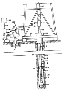
Figure 1 is a schematic view, partly in cross section, of an oil well drilling
and mud
pulse telemetry system employing the signal detection apparatus of the present
invention;
Figure 2 is an enlarged perspective view of the detection apparatus shown in
Fig. 1;
Figure 3 is an enlarged view of a portion of the detection apparatus shown in
Figure
2;
CA 02156224 1995-10-04
~~~3~3~~y
8
Figure 4 is an enlarged cross sectional view of a flow constrictor which
comprises a
portion of the detection apparatus shown in Figure 2;
Figure 5 is a top view of the flow constrictor shown in Figure 3.
DETAILED DESCRIPTION OF THE PREFERRED EMBODIMENTS
Figure 1 depicts a well drilling system configured for MWD operation and
having a
mud pulse telemetry system for orienting and monitoring the drilling progress
of a drill bit 1
and mud motor 5. A drilling derrick 10 is shown and includes a derrick floor
I2, draw works
13, swivel 14, kelly joint 15, rotary table 16 and drill string 8. Derrick 10
is connected to and
supplies tension and reaction torque for drill string 8. Drill string 8
includes a mud motor 5,
drill pipe 2, standard drill collars 3 (only one of which is shown), a mud
pulser subassembly
4, and drill bit 1. A conventional mud pump 18 pumps drilling mud out of a mud
pit 20
through conduit 19 to the desurger 21. Frorn desurger 21, the mud is pumped
through stand
pipe 22 and the rest of mud supply line 24 into the interior of the drill
string 8 through swivel
14. As well understood by those skilled in the art, the interior of the drill
string 8 is generally
tubular, allowing the mud to flow down through the drill string 8 as
represented by arrow 28,
exiting through jets (not shown) formed in drill bit 1. After exiting the
drill string 8, the mud
is recirculated back upward along the annulus 9 that is formed between the
drill string 8 and
the wall of the borehole 7 as represented by arrows 29, where the mud returns
to the mud pit
2U through pipe 17.
Although not shown in Figure 1, the drill string 8 also includes a number of
conventional sensing and detection devices for sensing and measuring a variety
of parameters
useful in the drilling process. A variety of electronic components are also
included in the drill
string 8 for processing the data sensed by the sensors and sending the
appropriate signal to the
pulser unit 4. Upon the receipt of the signals, pulser unit 4 sends a pressure
pulse to the
surface through the downwardly flowing mud 28 in the drill pipe 2.
CA 02156224 1995-10-04
~'i~~'j°::
w w f.r ~:
9
The pressure pulse is received and detected by bypass surface signal detector
100.
Detector 100 generally includes flow constrictor 30, bypass flow lines 32, 34
and differential
pressure transducer 50. As explained in more detail below, bypass flow lines
32 and 34
connect flow constrictor 30 in parallel with segment 23 of stand pipe 22 such
that acoustic
signals transmitted in the stand pipe 22 will also be sensed in the bypass
loop 31 (Fig. 2)
formed by flow constrictor 3U and bypass lines 32, 34. Transducer 50 senses
the pressure
pulses that are generated in the drilling mud by mud pulser 4. These pulses
travel to the top
of the borehole and are transmitted through mud supply line 24, stand pipe 22
and bypass loop
31 to transducer 50. Transducer 50 converts the pulses to electrical signals
and transmits the
signals via electrical conductor 98 to signal processing and recording
apparatus 99.
Referring now to Figure 2, segment 23 of stand pipe 22 is shown carrying
flowing
drilling mud, represented by arrow 28. As previously described, stand pipe 22
also conducts
die pressure pulses generated by the downhole mud pulser 4, such pressure
pulses being
represented by arrow 26. Mud flow 28 and pressure pulses 26 pass segment 23 of
stand pipe
22 travelling in opposite directions.
Referring to Figures 2 and 3, detector 100 further includes a pair of bypass
ports 40,
41. Each bypass port 40, 41 comprises a tapped access port in standpipe 22.
Such ports are
well known to those skilled in the art and generally include an extending
collar 42 having an
internally threaded portion 43 best shown in Figure 3. Bypass ports 40, 41 may
be positioned
at any location in the mud supply line 24 or conduit 19 which interconnects
mud pump 18 and
desurger 21; however, locating ports 40, 41 in stand pipe 22 has been found
successful in
practicing the present invention as well as convenient, as such ports
typically already exist in
locations along standpipe 22 for use with conventional pressure detection
apparatus.
Bypass lines 32, 34 may be connected to bypass ports 40, 41 in a number of
ways
known to those skilled in the art. One such connection means is shown in
Figure 3 where
CA 02156224 1995-10-04
~~~~Hrr.~'1
bypass line 32 is shown connected to bypass port 40 by means of adapter 37 and
end fitting
36 which is attached to and forms the termination of line 32. As shown,
threaded surface 43
of bypass port 40 threadedly receives a threaded extension of adapter 37. In a
like manner,
extension or stem 38 of end fitting 36 threadedly engages adapter 37. So
connected, the
interior passageway of bypass line 32 is thus in fluid communication with
segment 23 of mud
stand pipe 22, by which it is meant that mud from stand pipe segment 23 can
pass into bypass
line 32. Bypass line 34 may be connected to bypass port 41 in a similar
manner. As well
known to those skilled in the art, bypass lines 32, 34 may be interconnected
with ports 40, 41
using a myriad of other fittings and adapters other than those described so as
to achieve the
same fluid transporting arrangement.
Flow constrictor 30, best shown in Figure 4, generally includes tubular body
60 having
central longitudinal passageway or tluough bare 62 and a pair of radial bores
64, 66 which
intersect through bore 62. It is preferred that body 60 be manufactured from
stainless steel and
have a hexagonal-shaped cross section as shown in Figure 5. Through bore 62 is
generally
aligned with longitudinal axis 61 of constrictor 30 and includes two regions
68 and 69 having
substantially identical cross sectional areas. In the preferred embodiment,
bore segments 68,
69 have diameters of 0.54 inches and 0.50 inches, respectively. Disposed
between regions
68 and 69 is a coaxially aligned chamber 70 having a reduced cross sectional
area relative to
the cross sectional areas of regions 68 and 69. Preferably, chamber 70 has a
diameter
approximately equal to 0.25 inches. Tapered bore segments 72, 74 interconnect
chamber 70
with bore regions 68 and 69, respectively. The angle of the taper of bores 72
and 74, as
represented by arrows 76 and 78, preferably are approximately equal to 150
degrees and 170
degrees, respectively. The degree of taper of bores 72, ?4 may be varied from
those shown
and described; however, these tapers have been found to minimize the
undesirable noise that
may otherwise be generated by fluid turbulence inside body 6U. The ends of
longitudinal bore
CA 02156224 1995-10-04
~1~'~~
11
62 include tapped counterbores 80 and 82 to allow for interconnection with
bypass lines 32,
34 as shown in Figure 2.
Referring again to Figure 4, radial bores 64 and 66 are formed in body 60
approximately 180 degrees apart. In one preferred embodiment, radial bores 64
and 66 are
formed with diameters of approximately 0.339 inches and 0.062 inches,
respectively, although
these diameters may be varied to accurtunodate various sized pressure
transducers. Tapped
counterbores 84 and 86 are formed in body 60 and are aligned with radial bores
64 and 66 as
shown in Figure 4. Radial bores 64, 66 serve as pressure sensing ports as
described in more
detail below.
As best understood with reference to Figures 2 and 4, bypass loop 31 is
connected in
parallel with segment 23 of stand pipe 22 such that a proportionately small
amount of the
drilling mud flow passes through flow constrictor 30 in the direction shown by
arrow 63. The
mud pulse signal travels through body 60 in the opposite direction as
represented by arrow 65.
So connected, it is apparent that bypass lines 32, 34 must be capable of
containing what is
sometimes abrasive and corrosive drilling mud at relatively high pressures.
Bypass lines 32
and 34 are preferably flexible hydraulic hoses having inside diameters
approximately equal to
1/8 inch. A hose found to be particularly desirable in this application as
bypass lines 32, 34
is hydraulic hose manufactured by The Aeroquip Industrial Division of Aeroquip
Corporation
in Houston, Texas and which are capable of handling pressures of up to 3000
PSI. Bypass
lines 32, 34 may be any convenient length.
While a flexible hose is preferred for bypass lines 32, 34, rigid or semi-
rigid metallic
conduit or tubing may alternatively be employed. However, it has been found
that a flexible
hose is preferred for ease of handling and installation. High pressure
hydraulic hose is also
inexpensive, light weight and widely available. The hose has the additional
advantages that
it is mechanically simple and reliable.
CA 02156224 1995-10-04
~ +.,
~1W~;~; l
12
Bypass lines 32, 34 include end fittings 36 at each of their ends. One end
fitting 36 of
each bypass line 32, 34 threadedly engages tapped bores 80, 82 of flow
constrictor 30. The
end fitting 36 on the opposite end of bypass lines 32, 34 is connected to a
bypass port 40, 41
in stand pipe 22 as previously described. So connected, it will be apparent to
those skilled in
the art that bypass lines 32, 34 serve to transmit the pressure pulses 26 in
stand pipe 22 to the
parallel-connected flow constrictor 30 via the drilling mud which fills the
lines 32, 34.
Referring again to Figure 2, differential pressure transducer 50 includes two
pressure
input ports 51, 52. As known in the art, differential pressure transducer 50
compares the
pressures appearing at input ports 51 and 52 and generates an electrical
signal corresponding
to the difference in those pressures. The electrical output generated by
differential transducer
50 is communicated to signal processing and recording apparatus 99 (Figure 1)
via conductor
98. Transducer 50 may be any of the conventionally known differential
transducers presently
used for measuring pressures in mud pulses. One transducer found to be
particularly suited
for the present invention is transducer model no. 1151HP manufactured by
Rosemont Inc. of
12001 Technology Drive, Eden Prairie, MN 55344 ((612) 941-SS60). While a
differential
transducer 50 is preferred for use with detector 100, the pressures in regions
68, 70 may
instead be measured independently by discrete pressure transducers and the
outputs from these
transducers compared electronically by processes well known in the art.
Pressure transducer 50 is interconnected to flow constrictor 30 by pressure
comparator
lines 46 and 48. Lines 46 and 48 are preferably hydraulic hoses similar in
structure to bypass
lines 32, 34. Preferably, lines 46, 48 have inside diameters approximately
equal to 1/8 inch.
The ends of lines 46 and 48 include end fittings 36 such as previously
described with respect
to bypass lines 32, 34. Pressure comparator line 46 is connected between
radial bore 64 in
flow constrictor 30 and input port 52 in pressure transducer 50. Similarly,
pressure
comparator line 48 is connected between radial bore 66 in flow constrictor 30
and input port
CA 02156224 1995-10-04
F ~ e'~ ;
N ;a F.. ::
13
51 in pressure transducer 50. During installation, air is bled from bypass
lines 32, 34 and
from pressure comparator lines 46, 48, and the lines are allowed to fill with
drilling fluid to
insure that the acoustic signals will be transmitted to flow constrictor 30,
where they can be
detected by pressure transducer 50.
The operation and advantages of detector 100 are best understood with
reference to
Figuxes 1, Z and 4. Referring first to Figure 1, mud pulses 4 generates
acoustic signals 26 in
the stream of drilling fluid contained in drill string 8. The signal is
transmitted to the surface
and passes through mud supply line 24 and into segment 23 of stand pipe 22,
best shown in
Figure 2. The acoustic signal 26 also passes into bypass loop 31 containing
flow constrictor
30. The pressure signals pass through constrictor 30 in the direction shown by
arrow 65 in
Figure 4. The pressures detected in region 68 and in reduced diameter chamber
70 are
transmitted to differential transducer 50 via lines 46 and 48, respectively,
for comparison.
Because the flow constrictor 30 is in bypass loop 31, it is exposed to a
reduced flow
of drilling mud as compared to the flow in segment 23 of stand pipe 22.
Consequently, the
constrictor 30 is not as prone to erosion, and expensive hardfacing materials
need not be
applied to the body's interior surfaces. Likewise, because transducer 50 is
pasitioned in a
region of relatively stagnant drilling mud, it is similarly protected from
erosion and damage.
Further, by positioning the flow constrictor outside the main mud flow path,
the power
requirements of the system are not increased, as might otherwise be caused by
restricting the
main flow path. Additionally, the flow constrictor 30 may be much smaller than
would be
necessary if applied in the main mud flow supply line 24. The constrictor's
small size permits
quick and easy installation and, if necessary, replacement. The detector 100
may be simply
installed by drilling and tapping two bypass ports 40, 41 at any convenient
location in the mud
supply line 24 and by connecting the flow constrictor 30 to ports 40, 41 by
hydraulic hoses.
Installation is accomplished without cutting and removing a segment of the
relatively large pipe
CA 02156224 1995-10-04
. ~ a ;: ,. ;.,~ ,
NI~I~~~r
14
that typically makes up the mud supply system, and without the necessity of
welding
components into the supply line.
While the preferred embodiments of the invention have been shown and
described,
modifications thereof can be made by one skilled in the art without departing
from the spirit
and teachings of the invention. The embodiments described herein are exemplary
only, and
are iiot limiting. Many variations and modifications of the invention and
apparatus disclosed
herein are possible and are within the scope of the invention. Accordingly,
the scope of
protection is not limited by the description set out above, but is only
limited by the claims
which follow, that scope including all equivalents of the subject matter of
the claims.