Note: Descriptions are shown in the official language in which they were submitted.
WO 94/18897 21~ ~ 2 9 1 PCT/US94/02019
BONE A~ TISSUE L~ ;Nl~G DEVICE
Backqround of the Invention
This invention pertains to apparatus for extending or
lengthening bones and is particularly applicable to length-
ening of hllm~n bones. There are many instances where ahuman being has one limb, particularly a leg, which is
shorter than the other which could be congenital or due to
an accident. It has been found possible to lengthen the
deformed or shortened limb by devices which extend a proxi-
mal portion of a bone which has been severed from a distalportion. Such devices move the distal portion of the bone
away from the pro~;m~l portion in small increments. This
involves extending the gap between the severed bone por-
tions in increments of approximately 1/4 mm at a time.
When the bones are thus separated, new bone tissue grows in
the extended gap as well as soft tissue surrounding the
bone. It is possible to lengthen a bone such as a femur 10
or more centimeters over a period of a few months.
One such device was developed in the USSR by Gavriil
2 0 A . Ilizarov et al. which essentially is an extendable cage
which fits externally around a limb. The distal end of the
cage is incrementally extended from the prox-m~l portion
mechanically. One of the problems with this type of device
is that a plurality of pins are inserted through the muscle
25 of the limb, and into both portions of ~he bone. With the
prox;m~l portion of the limb "anchored" by the pins in the
cage, force is transmitted through the pins to pull the
distal portion away from the anchored portion. Such a
device is described in U.S. Patent 4,615,338. One of the
problems created by this type of device is that numerous
incisions are created in a limb by the pins which are
A~ C111~ 5_~5 ; ,~ ~ o4 ; ~Y ~ 'JJr ~ ); q
~ 21~6291
pulling on the fle~h. Anoth~r d~ad~ntage i~ tha~ the
wearing of a cage over a period o~ mGnt~s ~e~erely 1 imits
the mobility o~ thc patient .
N~mer~u~ other device~ employ an elongated rod or nail
known a~ a~ intramed~llary rod or nail. Such device~ ~re
in~erted into the ~arrow ca~rity or medullary pa~sage of the
~one. The~3e rods are often threaded and are anchored to the
~one ~rom within the medullar canal and ~re incrementally
~noved by nutl3 or r~chet nle~rlA ~c~ incrernent~lly continue
~eparati~g ~one po~tions. t3ne such early de~ice il3 shown in
.S. ~atent 3, 986, 504 to A~ila. The r~cheting ~r extending
o~ the threaded rod is accomplished externally by racheting
mech~ni ~m or wrenches . Again, this typ~ of device lends
it~el~ tc~ ect io~.
othe~ type~ of device~ ha-~e been de~reloped also ir. the
USSR by Alexand~r Bli~kuno~r and en~>loy r~eting devices
which are impl~nted intern~lly arld are operated by the
patient him~;elf who move~ p~rtion~ of hi~ b~dy to acti~rate
the racheting mechanism. C:rle problem with thi~ type of
de~ice i~ that accidental ma~e~ent or ex~es~i~e m~vemen- can
cauæe too much bone ~eparati~n, di~tur~ing the growth
patte~n. It is to the~e problemR that the pre~ent invention
i~ directed. Another o~jecti~e i8 to provide a co~pletely
implant~ble, hydr~ulically operated ~e~hAn;sm with a~ little
~ppo~tunity for infection as po~ible and which i~
substantially foolproo~ in operation.
U.S. Pa~ent 4 ,157, 715 to Westerhoff discl~se~ an
intracorpora} drive ~or an extens;on unit ~or exte~i~n
osteotomy ha~ing driving power generated by the o~motic
r,res:~sur~ be~ween two dlfferently c~ncen~raCed solution~;
separate~ f rom each other by a s~mipermeable diaphraam or
membrane .
s~ssTI TU rE SHEET PCT /Us ~ d~ / 0 2 01
AMENDED SHEET
LPA-Ml.iE~`H~ :~ u;~ . 5~ 5 . ~ ~ ~,4 HkS~K~ (~4~ UY ~ 44~
- 215G291
--2~1-
lJ.S. P~tent 5,~74,88~ to ~;ra~nort et al. di~closes a
n~il for gr~dt~lly lengthening long bones incl~ding o~ter
and inner ~liding t~es ~onnected by a double r~tchet
mech~ni sm .
Sumrnar~ of the In~rention
A device for 1 engthenin~ bone and ti~-~ue in a human or
iLnimal 1~ di~clo~ed ~or incre~entally extending the diatanc~
betwe~n d:iscrete sep~rated portion~ ~f the bo~e to permit
contimled growth between the ~eparated porti~ns. It
include~ an intramedullary nail ~avin~ a di~tal portion and
SUBSI'II~E SHI~ET PCT/US94/0201
AMENDED SHEET
WO94/18897 PCT~S94/02019
2156291
includes an intramedullary nail having a distal portion and
a proximal portion. The proximal portion of the nail is
secured within the intramedullary canal of the bone at the
proximal end thereof and the distal portion of the nail is
secured within the intramedullary canal at the distal end
thereof. A hydraulic cylinder is connected to the proximal
portion and a piston moveable in the cylinder is connected
to the distal end of the nail. There is an implantable
supply of operating fluid in communication with the cylin-
der and racheting mechanism is located between the proximaland distal portions of the nail, i.e., the piston and
cylinder, to limit their relative movement to one direc-
tion.
An alternative racheting mechanism, however, permits
the pro~;m~l and distal portions of the nail (i.e., piston
and cylinder) to reverse directions when the pressure of
the operating fluid is released.
A shock absorbing member is interposed between the
piston and the cylinder and cooperates with lost motion
mechanism to provide a small amount of buffered lost mo-
tion, creating an environment to enhance growth between
the separated portions.
The pressurizable fluid is contained in an implantable
reservoir which may be pumped either m~n~ ly or from an
external signalling device or an internal pump controlled
by an implantable battery operated microprocessor.
It will be understood that the device, while illus-
trated as lengthening the femur, can with simple modifi-
cation be adjusted to lengthen all long bones.
The above and other features of the invention, includ-
ing various novel details of construction and combinations
of parts will now be more particularly described with
reference to the accompanying drawings and pointed out in
WO94/18897 PCT~Sg4/~2019
215~291
--4--
the claims. It will be understood that the particular bone
and tissue lengthening device embodying the invention is
shown by way of illustration only and not as a limitation
of the invention. The principles and features o~ this
invention may be employed in varied and numerous embodi-
ments without departing from the scope of the invention.
Brief Description of the Drawinqs
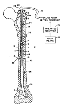
Figure 1 is a sectional view of a bone length~n;ng
device embodying the present invention and which is located
in the femur. Figure 2 is a detail view of an upper por-
tion of the device shown in Fig. 1.
Figure 3 is a detailed sectional view on an enlarged
scale taken on the lines III-III of Fig. 2 of rachet means
for limiting movement of the device shown in Fig. 1.
Figures 4, 5 and 6 are detailed enlarged views of an
alternative embodiment of the racheting mechanism including
means for reversing the direction of the mechanism.
Figure 7 is a detail view of means for supplying
pressurized operating fluid to the device.
Figure 8 is an alternative embodiment of the means for
supplying pressurized operating fluid.
Detailed Description of the Invention
A device for length~n;ng bone and soft tissue in a
hllm~n or other animal by incrementally extending the dis-
tance between discrete separated portions of the bone or
tissue to permit continued growth between the portions will
be seen in Fig. 1. The device is shown inserted into a
human femur 2, although it could be another bone in a human
or ~n;m~l. Initially, a surgeon removes the soft, pulpy
material in the medullar canal to produce an elongate
opening. He then cuts the bone transversely as at 3 to
W094/18897 PCT~S94tO2019
21562~
receive an intramedullary nail or rod generally designated
4.
The rod includes a distal portion 6 and a proximal
portion 8. The proximal portion has formed in it a central
bore 10 which leads to a cylinder 12 having an upper, domed
shaped, fluid chamber 14. The pro~;m~l portion terminates
at a point designated 16. A plate 18 is secured by screws
20 to the femur. A one-way valve 22 is threaded into the
plate 18 and/or portion 8 and is secured by a nut 24 at the
proximal end of the femur. A flexible conduit 26 leads
from the one-way valve 22 to an implanted reservoir 30
(Fig. 1) which, in turn, is actuated by a pump 32, both
elements to be described in greater detail hereinafter.
The proximal portion 8 of the intramedullary nail is se-
cured to the femur by screws 34. The diætal portion 6 of
the intramedullary nail is secured by screws 36 within the
distal portion of the medullar canal and on its upper end
is formed a piston 9. Ratchet teeth 40 are formed in a
line 42 in the piston 9.
A collar 44 is secured to the piston 9 by screws 48
and is received within an annular groove 46 in the cylinder
12. A dog 46 is received within a slot 49 in the collar 44
for movement inwardly and outwardly radially with regard to
the piston and has teeth 50 engagable with the mating teeth
40 formed in the piston 9. A fluid tight gasket 51 is
fitted in a groove in the piston 9 a~d engages the wall of
the cylinder 12. An annular, elastomeric shock absorbing
element 52 is engagable with the sleeve 44 and the top 55
of the slot 49.
Lost motion between the piston 12 and the cylinder 4
occurs to the extent of the gap 54 between the sleeve 44
and the slot 49 as the patient's lower leg is moved, thus
causing the lower cut portion of the femur to move or
WO94/18897 PCT~S94/02019
g~
--6--
vibrate slightly relative to the upper cut portion. Inother words, the piston is permitted a small amount of lost
motion relative to the cylinder, buffered by the shock
absorber 52, which motion or vibration is beneficial to
bone growth.
The dog 46 is urged to the left as seen in Fig. 3 by a
compression spring 56 which is received within the sleeve
44. When the piston 9 and, hence, the distal portion of
the bone, is urged downwardly by pressurized fluid entering
the chamber 14, the dog 46 is moved slightly to the right
as viewed in Fig. 3 by the teeth 44. Each tooth moves
downwardly engaging the next adjacent tooth. This limits
the motion of the distal end of the nail relative to the
proximal portion to one direction. Thus, the piston can
only move out of the cylinder upon admission of pressurized
fluid to the chamber 14 above the piston head and not
reverse direction. This will be done by the surgeon when
the bone growth is completed.
An elastomeric piston cap 60 (Fig. 2) is secured by a
screw 62 to the top of the piston member 9. The edges of
the cap 62 maintain a seal against the inner walls 64 of
the cylinder 12 which in conjunction with the annular seal
51 assures that there is no leakage of the saline operating
fluid.
Referring next to Figure 7, there will be seen an
implantable supply of saline operating fluid 70 contained
within an elastomeric diaphragm reservoir 72, implanted and
secured by sutures 74 on an inner portion of the skin and
muscle of the patient generally indicated 76. A ferro-
magnetic disk 78 is secured in an upper domed portion 73 of
the diaphragm reservoir. The implanted conduit 26 which
leads to the one-way valve 22 of the cylinder communicates
with an opening 80 in the fluid reservoir 72. An exter-
WO94/18897 PCT~S94/02019
.
215629~
nal pump exciting member 82 is engagable with the skinadjacent the ferromagnetic disk 78. It comprises an elec-
tromagnet 84, a battery 86 and a trigger 88 such that a
surgeon or even a patient can trigger the exciting member
to cause the ferromagnetic disk 78 to pulse toward and away
from the electromagnet 84 to compress and relax the dia-
phragm reservoir to cause the saline fluid to pass through
the conduit 26 through the one-way valve 22 and into the
domed reservoir 14 at the top of the piæton.
An alterative pumping mechanism is shown in Fig. 8.
The reservoir 72 is connected by a flexible conduit 88 to a
pump 90 operated from a reversible geared motor 92. A
programmable microprocessor 94, through batteries 96,
supplies signal to the motor 92 to pump fluid from the
reservoir through the conduit 26 into the upper domed
portion 14 of the cylinder 4. The motor 90, being revers-
ible, may also pump fluid back to the reservoir 72.
With reference to Figs. 4, 5 and 6, mechanism for
reversing the direction of the piston 9 within the cylinder
12 will now be described. At the top of the piston, an
inverted, bell shaped seal 100 is provided which is mounted
for flexure between a pair of hinged racheting wings 102,
104, having teeth 106 which are engagable with mating teeth
108 on the interior of the cylinder wall. The wings 102,
104 are pivoted on a rod 112 received within bores in the
top of the piston 9. The piston is cut away at 114 to
accommodate the lower ends of the wings which piVGt in-
wardly and outwardly under the control of a coiled spring
116. When it is desired to incrementally separate the
proximal and distal portions of the bone, the implantable
reservoir 72 is pressurized either externally by the elec-
tromagnet 82 or, preferably, by the microprocessor operated
pump 90 because the system is reversible. This causes
WO94/18897 PCT~S94/02019
2~6~
fluid to flow through the flexible tube 26 through the
passageway 10 into the upper domed portion 14 of the cylin-
der. The pressurized fluid acts against the seal 100
expanding its upper annular portion 101 to expand against
the cylinder walls as shown in Figs. 4 and 5. The pressure
urges the wings 102, 104 apart against the force of its
spring 116. The teeth 106 engage the teeth 108 in the
cylinder walls, one by one. Continued pressurization urges
the piston 9 downwardly causing the bones to separate and
permit new growth to take place.
If, for some reason, the bone portions have been
separated too much or it is desired to terminate the bone
growth, depressurization of the fluid above the piston
permits the coiled spring 116 to squeeze the seal 100
together as shown in Fig. 6 with the pressurized saline
fluid reversing direction in the passageway lO and return-
ing to the reservoir 72. The reversible pump 90 controls
the fluid reversal.
Without using the pump 90, with the teeth 106 on the
wings 102, 104 withdrawn from the teeth 108 on the inner
cylinder walls, pressure on the distal end of the bone, as
for example, by the orthopedist applying counter pressure,
can cause the piston 9 and the distal end of the bone to
rise slightly, closing the gap 3 between it and the proxi-
mal portion of the bone.