Note: Descriptions are shown in the official language in which they were submitted.
21~6305
~O 95/lC868 ~CT/BP94/0-
~18~
CONTINUOU8 ~YDR08TATIC POWER DIVI8ION TRAN8~I8~ION
The invention is concerned with a continuous hydrostatic power
division transmission, especially with the hydrostatic
transmission part of this transmission, in detail, with the
characteristics of the main clause of Claim 1.
Continuous hydrostatic power division transmissions, abbre-
viated below as C~P, make it possible to change speed without
interruption of the tensile force, with synchronous rpm, and
without load. The principle and the structure of continuous
hydrostatic power division transmissions are known, for
example, from publications
1) DE 28 10 086
2) DE 29 045 72 C2.
Such transmissions include hydrostatic and merh~nical
transmission parts which are coupled to each other in such a
way that the power to be transmitted is transmitted to certain
parts in the individual driving regions hydraulically and/or
m~r~nically. The power division makes it possible to improve
efficiency in comparison to a purely mechanical or a purely
hydrostatic transmission. Both hydrostatic units can be
driven as a pump and as a motor.
The transmissions that have thus far been realized in the art
which are based on conventional solutions for use in passenger
cars and heavy vehicles, have significantly larger dimensions
and a correspondingly increased weight, and are less cost-
effective in comparison to automatic torque converter
transmissions.
215~3~5
WO 95/16868 PCT/EP94/0-
~18~
Based on favorable characteristics, for example, a high start-
up torque, better insensitivity of the system, a larger
control range in variable displacement motors, significantly
higher efficiency, as well as the possibility of higher
limiting rpm and speed increasing ratios, the two hydrounits
are designed as slanted axis units which can be operated as a
pump and as a motor. However, the large dimensions and high
noise level that generally are characteristics of hydrostatic
transmissions represent problems.
Furthermore, integration of a slanted-axis hydrostat into a
CHP transmission concept has not been possible so far in such
a way that optimum arrangement of the other components could
be achieved with a tolerable manufacturing cost. In general,
in the conventional solutions, the hydrostatic units are
flanged outside of the transmission housing of the mechanical
transmission part, i.e., all parts that carry high pressure
are disposed outside the transmission housing. Optimization
of the constructional size of the hydrostat has not been
possible since back gear transmissions have been limited by
the distance between the axles and the shaft diameter. Also,
the start-up pulling force was the essential design criterion
for the hydrounit~ to be used. The realization of a
marketable transmission regarding the size of the structure
and its cost has thus so far had limited possibilities.
In a device disclosed in DE 36 24 989 C2 wherein two
hydrounits are used as premounted units with a connecting or
control block, the transmission design is very compact. The
hydrostats are disposed in the inner casing of the planetary
gear and the control heads of the hydrostats are disposed
against each other at such an angle that their ends almost
touch and extend tangentially to the envelope toward the top
and bottom. As a result, the space required by the structure
is minimized. Disadvantages of such an arrangement consist
215630~
WO 95/16868 PCT/E~9~/0-
~18~
above all in increased manufacturing costs for the control
block and realization of energy coupling of the hydrounits
based on the angled orientation of the control heads, and thus
in providing a flange designed for this; furthermore, there is
also no poæsibility of reducing the size of the hydrounits.
Therefore, the task of the invention consists in avoiding the
above disadvantages and in further developing a CHP unit of
the type explained at the outset in such a way that one can
produce a transmission which is marketable from the point of
view of size and cost. The dimensions and the weight of the
transmission are to be reduced using commercial hydrostatic
components to the extent that these reach the magnitude of
transmissions that are on the market today, for example, of
torque converter transmissions, without having to consider the
technical disadvantages. At the same time, it is of enormous
importance for the use of CHP transmissions in passenger
vehicles and in the heavy vehicle area to acoustically
decouple the two hydrounits from the housing in order to
reduce noise levei as much as possible, the noise mainly being
caused by the hydrostatic transmission part.
The task is solved by the characterizing parts of claim 1.
Advantageous embodiments are given in the subclaims.
By disposing two hydrostatic units with their axes slanted and
next to one another in such a way that their driving and
driven shafts (depending on whether operated as a pump or as a
motor) have parallel axes, but are oppositely oriented and
displaced with respect to one another a maximum distance of
the length of one hydrounit in a direction of the axis of
symmetry of the driving shaft or driven shaft of one of each
of the hydrounits, so that the drum axes are disposed in a
plane, there is a possibility of integration of the hydrounits
together with the mechanical transmission part in a common
2 1 ~
~0 95/16868 PCT/~P94/0-
~18
transmission housing, preferably above and below the
me~hAnical transmission part in fitting position. A sidewayc
arrangement, i.e., one according to the invention, in the
vertical direction or fitting position, can also be considered
if the oil Cump is displaced. The hydrostatic transmission
part can be disposed in the region of the mechanical
transmission part without increasing the dimensions of the
entire transmission with respect to the purely mechanical part
of the transmission. In order to keep the dimensions of the
entire assembly as small as possible, the slanted-axis
hydrostats are preferably oriented with respect to one another
in such a way that the drums of the hydrounits are directed
toward one another in a moved-out state.
The extensions of the axes of symmetry of the driving and
driven shafts of each hydrounit and straight lines drawn
through the intersections of the outside contours of one of
each hydrounit with the symmetry axes describe a
parallelogram. The energy coupling of the two hydrounits is
done via tubings which are disposed between the two hydrounits
in such a way that these essentially describe a diagonal of
the parallelogram.
The integration of the hydrounits with the mechanical part of
the transmission in a common transmission housing allows
creation of a transmission in a compact form into which even
the high-pressure parts of the hydrostatic part of the
transmission are integrated, so that, in case of leakage, no
oil can escape to the outside.
Providing at least one additional intermediate shaft makes it
possible to increase the start-up speed increase ratio of a
hydrounit and thus the use of smaller hydrostats, as a result
of which, in the final analysis, the dimensions of this can be
adapted better to the entire transmission concept.
21~6~0~
WO 95/16868 PCT/~P9~/0-
~184
Furthermore, as a result of the speed increase ratios, the
same hydrounits can be used in the structure and in the
design. When using different hydrounits, the jump in
structure size can be reduced considerably.
s
Preferably, slanted-axis-built hydrounits of the same series
can be used as hydrounits, i.e., the same hydrsunits with
regard to structure, size and design. The placement of the
second hydrounit next to the first hydrounit is accomplished
in such a way that an axis is present between the two
hydrounits, with reference to which the two hydrounits are
oriented with respect to one another with axial symmetry. The
position of the second hydrounit is obtained by rotation of
180 around this axis, which is directed perpendicularly to
one of the planes defined by the axis of symmetry of the
driving and driven shafts of the hydrounits. The position of
the axis is chosen in such a way that the two hydrounits are
disposed directly next to one another without any significant
displacement in the direction of the axes of symmetry. In
such an embodiment, the extension of the axes of symmetry of
the driving shaft and driven shaft of each hydrounit and the
straight lines laid through the intersections of the outside
contours of the hydrounits with the extended symmetry axis
describe a rectangle. The hydraulic connecting lines,
preferably designed in the form of tubes, are disposed between
the two hydrounits and essentially define a diagonal of the
rectangle. In connection with a transverse bar or connecting
lines disposed between the two hydrounits, the two hydrounits
always describe a letter Z and therefore this arrangement can
also be called a Z arrangement. The two hydrounits are
disposed parallel to one another but reversed right-to-left
with respect to one another. An especially positive aspect of
this embodiment is that this arrangement requires the least
constructional space in the entire transmission in compArison
to transmission arrangements of the conventional design, and
~O 95/16868 2 1 5 6 3 ~ ~ PCT/ ~P9 ~ / O -
418
thus the possibility of building a very compact total
transmission is created.
Based on the orientation of the driving and driven shafts of
the individual hydrostats and their drum axes in a common
plane, no additional manufacturing expenditure is re~uired in
the production of hydrostats for realization of the energy
coupling between the hydrostats, and the same is true for the
integration of the control block.
The control block is preferably integrated in the connecting
block. With corresponding disposition of the individual valve
functions, the control block and connecting block can be
structured symmetrically. In addition, there is also the
possibility to integrate the adjustment or adjustment devices
of the hydrounits in the connecting block. This provides the
advantage that the connecting block can be arranged without
consideration of the connections or design of the connecting
sides of the individual hydrounits to the housing end
surfaces, that is, the connecting block can also be
incorporated, turned by 180. Another possibility to make the
entire unit significantly more compact consists in integration
of the housing end parts of the hydrounits in the connecting
block.
In the transmission embodiment recited in the main clause of
Claim 1, the hydrounits can be disposed in the region of the
outer crown of the planetary differential whereby the distance
between the axes of the driving and driven shafts of the two
hydrounits depends on the size of the planetary differential.
A significant advantage of this embodiment consists
furthermore in the fact that the two hydrounits can be
combined into a single assembly, which can be premounted,
tested, and incorporated into the transmission as a single
215~
~o 95/16868 PC~/~P9~/0-
418~
assembly. For this purpose, two hydrounits are rigidly joined
to each other with at least one bridge or transverse bridge.
The connection is preferably done to bridges applied onto the
housing. As recited in claim 12, the entire assembly can then
be elastically hung in the transmission.
Advantageously, the integration of the hydrostatic part of the
transmission into a transmission housing is accomplished
together with the mech~nical part of the transmission. The
high-pressure parts are all integrated in the housing so that
in case of leakage, no oil can reach to the outside. The
hydrostatic transmission part can be handled and mounted
easily in the form of a single assembly. A CHP transmission
with two hydrounits oriented according to the invention i8
characterized by smaller dimensions of the entire
transmission, lower noise emission, and lower cost in
comparison to the CHP units having a conventionally oriented
hydrounit.
The magnitude of the distances between the axes of symmetry of
the driving and driven shafts of the hydrounits can be
minimized, but is always dependent on the structure of the
mechanical part of the transmission and on the orientation of
the hydrostatic part of the transmission in the total
~5 transm1ss1on.
A purely hydrostatic transmission in a very compact form can
be created according to another aspect of the invention
wherein two hydrostatic units are disposed next to one another
in such a way that the position of one of the hydrostatic
units is obtained by turning the other hydrostatic unit by
180 around an axis which is perpendicular to a plane going
through the axes of symmetry of the driving and driven shafts
of the hydrounit, and the displacement of which, in the
direction of the axes of symmetry is essentially zero, as well
21~53V~
WO 95/16868 PCT/EP94/0-
4184
as that the connection of the two hydrounits is accomplished
with at least one transverse bridge. The drum axes of the
individual hydrounits are in one plane. The assembly is
characterized by simple and easy handling and can be obtained
completely premounted and tested.
The solution of the task according to the invention is
explained below with the aid of figures. The following are
shown in these:
Figure la shows an arrangement of two hydrounits in one
assembly according to the invention.
Figure lb illustrates schematically an arrangement of the
hydrounits in the Z arrangement in a CHP transmission
according to the invention.
Figure 2 illustrates schematically the coupling of the
hydrounits in the Z arrangement in a CHP transmission.
Figures 3a to c explain the structural rearrangement within
the total transmission concept according to Figure 1 with
flanged-on control block.
Figures 4a to 4c illustrate schematically other possibilities
of defining the control block.
Figures la and lb show a preferred embodiment of an
arrangement of two hydrostatic units Hl and H2 according to
the invention having a slanted-axis structure, and their
combination to a single assembly. The two hydrounits Hl and
H2, preferably commercially available ones, are disposed in a
plane E1, as can be seen from Figure lb. The plane E1 is
215~30~-
Wo 95/168C8 PC~/EP9~/o-
~184
axes of symmetry A1 and A2 of the driving and driven shafts of
the individual hydrounits Hl and H2.
Preferably, the two hydrounita are similarly designed. Both
hydrounit~ are axially symmetrical with respect to an axis A,
which is directed perpendicularly to a plane E1, that is, the
position of the hydrounit H2 can be described by turning the
hydrounit H1 by 180 around the axis A. The position of the
axis A is chosen in such a way that both the hydrounits H1 and
H2 are disposed directly next to one another without
displacement in the direction of the axes of symmetry of their
driving and driven shafts. The extensions of these axes of
symmetry A1 and A2 of the driving and driven shafts of each of
the hydrounits H1 and H2 and the straight lines Gl and G2
drawn through the intersections of the outside contours of the
hydrounits with the axes of symmetry, describe a rectangle.
Drum axes T1 and T2 of the hydrounits H1 and H2 also lie in a
common plane, which is the same as the plane E1, which goe~
through the axes of symmetry A1 and A2 of the driving and
driven shafts of the two hydrounits Hl and H2.
The two hydrounits are coupled to each other through a
connecting block including connecting lines, in the embodiment
shown in the form of pipelines 3. These are disposed between
the two hydrounits Hl and H2. Preferably, the two hydrounits
are rigidly joined to a single unit (assembly 8) with at least
one cross bridge 7. The cross bridge 7 is joined to the
housings of the two hydrounits. The valve functions are
integrated into a control block 6. In the examples shown
here, this control block 6 is disposed on the hydrounit H2 in
order to keep the valves accessible from the outside in case
they are contaminated. However, it is possible to integrate
the control block 6 directly into the pipelines 3.
21~30~
~O 9S/168C8 PCT/FY94/0-
~18~
The entire assembly 8 can be connected to the transmission
housing, not shown here, via elastic elements 4, and can be
coupled through couplings 5a and 5b to the corresponding
shafts, for example, to the shafts of the mechAnical
transmission part of a CHP transmission.
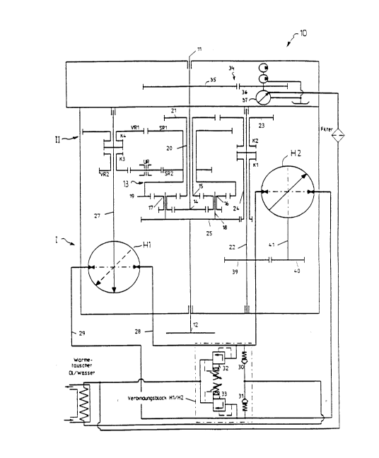
Figure 2 shows schematically the arrangement of the two
hydrounits in a CHP concept according to a proposal made
internally. The power division transmission, generally
designated 10, consists of a hydrostatic transmission part I,
including two hydrounits Hl and H2, which can be operated as a
pump and as a motor, and a mechanical transmission part II. A
driving machine, not shown, is connected on the side of the
transmission input shaft 11. A transmission output shaft of
lS the power division transmission 10 is designated 12. There is
a planetary differential 13 disposed between the transmission
input shaft 11 and the transmission shaft 12. The
differential includes a large sun wheel 14, a small sun wheel
15, double planet wheels 16 and 17, a bridge shaft 18, and a
hollow wheel (annulus) 19. The large sun wheel 14 is
nonrotatingly connected to the transmission input shaft 11.
The small sun wheel 15 is nonrotatingly connected to a hollow
shaft 20, on which, again, a toothed wheel (gear) 21 is
nonrotatingly disposed. The toothed wheel 21 meshes with a
toothed wheel 23 which is disposed on a shaft 22 so that it
can rotate. A toothed wheel 39 is nonrotatingly attached to
the shaft 22 and meshes with a toothed wheel 40, which is in
nonrotating connection with a shaft 41, which functions as the
driving or driven shaft of the hydrounit H2. The shaft 22
represents the mech~nical connection between the hydrounit H2
and the planetary differential transmission 13, as an
intermediate shaft. Furthermore, a toothed wheel 24 can be
nonrotatingly connected to the shaft 22 with the aid of a
coupling K1, which is engaged with a toothed wheel 25 that is
nonrotatingly connected with the transmission output shaft 12.
215630~
~O 95/16868 PCT/EP94/0-
~18~
With the aid of a coupling K2, the toothed wheel 23 can be
nonrotatingly coupled to the shaft 22.
A spur pinion SR~ and a spur pinion SR2 are nonrotatingly
connected with the hollow wheel 19. The spur pinion SRl meshes
with a countertransmission VR~ and the spur pinion SR2 meshes
with a countertransmission VR2 through a reverC~e wheel UR.
Both countertransmissions VR1 and VR2, can be coupled
optionally with clutches K3 and K4 to a shaft 27, which
functions as a driving shaft or a driven shaft of the
hydrounit H1.
The hydrounits H1 and H2 are joined together with connecting
lines 28 and 29. The hydrostatic coupling of the hydrounit H1
to the hydrounit H2 is done via the control block H1/H2, which
includes two check valves 30 and 31 for feeding the amount of
oil leaked and two relief valves 32 and 33 to limit the
maximum pressure.
The oil is supplied to the hydrounits via a feed pump 37
driven by the driving machine through a spur pinion stage 34,
including a spur pinion 35, which i8 nonrotatingly joined to
the transmission input shaft 11, this spur pinion being
engaged to a spur pinion 38 which is nonrotatingly joined to
the drive shaft 36 of the feed pump 37.
The rate of rotation of the transmission output shaft 12 i8
the sum of the rates of rotation of the large sun wheel 14 and
of the hollow wheel 19, which determine the rate of rotation
of the planet wheels 16 and 17 and of bridge shaft 18.
In a top view, the two hydrounits H1 and H2 are arranged in
such a way that their driving and driven shafts 14 and 27 are
directed opposite to one another, as a result of which, in
2 1 ~
~O 95/16868 PC~/EP94/0-
~18~
contrast to the internal solution, the additional intermediate
states 39/40 could be integrated. The advantage of this is
that the speed increase ratio to hydrounit H2 can be increased
by about 50% without exrPe~;ng the limiting rates of rotation
of the hydrostats.
Figures 3 show a constructive arransement of the two
hydrounits into one assembly 8 according to Figure 1 in a
total transmission concept of a continuous hydrostatic power
division transmission according to Figure 2. Therefore, in
the following description, the same reference numbers are used
for the same elements.
Figure 3a shows the arrangement of assembly 8 which was
already described in detail in Figure 1, in a total
transmission concept according to Figure 2 in a top view.
However, the mPchAnical part of the transmission is not shown
for the sake of clarity. The hydrounits Hl and H2, which are
combined to an assembly 8 with the aid of the transverse
bridge 7, are connected to the transmission housing 9 with the
aid of the elastic elements 4a and 4b. The mechanical
transmission part 1, which is not shown here for the sake of
clarity, is also integrated into this transmission housing 9.
The hydrounits Hl and H2 are coupled to shafts 27 and 41
through couplings 5a and 5b, which can be designed, for
example, in the form of a curved teeth couplings. The
hydrounits are coupled to the planetary differential
transmission through spur pinions nonrotatingly connected to
these shafts, but the spur pinions are not shown here
individually.
Figure 3b shows the top view as shown in Figure 3a, with the
mechanical transmission part drawn in. The hydrounit H2 is
disposed below the intermediate shaft 22.
12
21~305
~O 95/16868 PCT/ EP9 4 / O -
~18~
Figure 3c show~ a section through the transmission according
to Figure 3b. It can be seen from this representation that,
when the hydrounits are of a small size, there is a
possibility to disposed the hydrounit~ essentially below the
outer crown of the planetary differential transmission 13.
However, here, only the head circle diametQrs of the
individual elements of the planetary differential transmission
are shown. In the embodiment that i8 illustrated here, the
arrangement is accomplished in connection with the arrangement
shown in Figure 3b below the hollow wheel 19 and above the
spur pinion 25 connected to bridge shaft 18. This has the
advantage that the space required by the mechanical part of
the drive does not have to be enlarged in the axial direction
as it would be in any embodiment in which the mer-hAnical and
hydrostatic transmission parts would be displaced in the axial
direction. Both of the hydrounits are disposed in the
transmission sump.
Figure 4a shows schematically, and as an example, the
integration of the control block with two pressure limiting
valves into the connecting block 3. Preferably, the control
block is designed in such a way that a pressure limit valve is
assigned to each hydrounit Hl and H2 on the high-pressure
side. Thi~ provides the advantage that the control block 6,
and thus the connecting block 3, can be constructed
symmetrically, as a result of which, the control block can be
disposed on the housing end surfaces of the individual
hydrounits without consideration of the connections or the
design of the connecting sides.
Figure 4b shows the additional integration of hydrostat
adjustments (40, 41) in the connecting block 3, by way of
example.
~15~o~
~0 95/1686~ PC~/~P9~/0-
418~
Figure 4c schematically shows the constructive design in a
very simplified form. The connecting block 3 can be flanged
onto the end housing of the particular hydrounit H1 and H2.
However, it is also possible to integrate the end housing of
the hydrostats with the connecting block.
According to another aspect of the invention, the hydrostatic
transmissions can also be designed in the form of the assembly
described here when the driving and driven shafts are not very
far-removed from each other.