Note: Descriptions are shown in the official language in which they were submitted.
WO 94/21851 ~ ~ ~ PCT/US94/03176
1
"ALIGNED FIBER REINFORCEMENT PANEL FOR WOOD MEMBERS"
' Technical Field
This invention pertains to reinforcement of
' structural wood, such as beams, columns and trusses.
More particularly, the present invention pertains to the
use of unidirectional fibers as a reinforcement in struc-
tural wood members to improve the tensile or compressive
loading of the wood member.
Backaround Art
To remain competitive, wood product engineers
have had to adopt innovative designs in combination with
alternate materials to enhance the structural limits and
cost effectiveness of engineered wood products. Examples
of engineered wood products include glued laminated wood
beams, laminated wood columns, wood I-beams, and wood
trusses. The prior art is replete with examples of these
engineered wood products.
O'Brien, U.S. Patent No. 5,026,593 discloses
the use of a thin flat aluminum strip to reinforce a
laminated beam. O'Brien teaches that the aluminum strip
must be continuous across the width and length of the
beam and that the reinforcing strip may be adhesively
fixed to the lowermost lamina to improve tensile
strength, or to the uppermost lamina to improve strength
in compression of the beam. Thus, while O'Brien teaches
the engineering principal of locating a reinforcement
strip in a wood laminated beam to improve the tensile
strength (or strength in compression) of the beam and
thus to improve the overall load carrying capacity of the
beam, O'Brien only teaches the use of an aluminum rein-
forcing strip. And although O'Brien states that the
reinforcing strip may be any "high tensile strength"
material, O'Brien does not teach nor suggest means for
optimizing the reinforcing strip nor of solving problems
CA 02156417 1999-OS-26
2
associated with the use of reinforcing strips other than
aluminum.
At the 1988 International Conference on Timber
Engineering, a paper was presented entitled "Reinforced Glued-
Laminated Wood Beams" by Mr. Dan A. Tingley (hereinafter
"Tingley paper") that disclosed the use of reinforced plastics
(RP) in glue laminated wood beams (glulams). The Tingley paper
disclosed test results of glulams having "KEVLAR" (Trade-mark)
reinforced plastic panels) located at high stress areas. The
results indicated a 19a improvement in ultimate load-to-
failure of beams with "KEVLAR" reinforcement as opposed to non-
reinforced beams. Although not disclosing why longitudinal
alignment was desirable or how it was achieved, the paper
states that the manufacturers were able to achieve one hundred
percent longitudinal alignment of fibers. The paper also
disclosed that the reinforcing panel was sanded on two sides
and further stated that the sanded surfaces of the "KEVLAR"
reinforced panel was found to be important. However, the
paper does not disclose why the sanding was important nor a
suggestion that the sanding process exposed or abraded the
"KEVLAR" fibers. The Tingley paper also teaches that there
are economic advantages to shortening the length of the RP
relative to the length of the glulam beam without significant
reduction of reinforcement benefit in beam strength. The
Tingley paper does not disclose any process for fabricating RP
reinforcement panels, nor benefits associated with curing the
panels while the fibers are in tension to reduce initial
strain. Nor does the paper disclose the benefits of exposing
some of the outermost fibers in order to "hair up" the RP to
produce a surface that facilitates the use of commercial grade
adhesives such as resorcinol. On the contrary, the paper
teaches away from resorcinol adhesives by teaching the use of
epoxies to adhere the RP to the surrounding wood laminae even
though the less
71073-50
CA 02156417 1999-O1-15
- 3 -
expensive commercial adhesive, resorcinol, was used between
the other layers of wood laminae.
Another area of related art is the fabrication
process of pultrusion. Pultrusion is defined as a continuous
manufacturing process for producing lengths of fiber
reinforced plastic parts. Pultrusion involves pulling
flexible reinforcing fibers through a liquid resin bath and
then through a heated die where the RP is shaped and the resin
is cured. Pultrusion is known for its ability to fabricate a
continuous length of RP and to accommodate custom placement
and orientation of fibers, which allows for the mechanical
properties of the pultruded part to be designed for a specific
application. Pultruded parts have longitudinally aligned
fibers for axial strength and obliquely aligned fibers for
transverse strength.
Disclosure of the Invention
The invention provides a panel to be adhered to an
elongate wood structural member for increasing a load carrying
capacity of the structural member, said panel comprising: (a)
a plurality of reinforcing fibers, a substantial majority of
which are continuous along the length of said panel, arranged
substantially parallel to one another and aligned so as to
comply with a longitudinal direction of said structural member
when said panel is adhered to said structural member; (b) a
resin encasement for said plurality of reinforcing fibers
maintaining said parallel arrangement and said longitudinal
alignment; and (c) fiber material originating from aligned
71073-50
CA 02156417 1999-O1-15
- 3a -
reinforcing fibers closest to a major surface of the panel
protruding from the resin encasement of that surface.
The invention further provides a panel to be adhered
to an elongate wood structural member for increasing a load
carrying capacity of the structural member, said panel
comprising: (a) a plurality of continuous fibers along the
length of said panel, arranged substantially parallel to one
another and aligned so as to comply with a longitudinal
direction of said structural member when said panel is adhered
to said structural member; (b) a plurality of noncontinuous
fibers originating from said plurality of continuous fibers
and protruding therefrom; and (c) resin encasing all of said
continuous reinforcing fibers but not all of said protruding
fiber material so that fiber ends protrude beyond the encasing
resin along a major surface thereof and serve to facilitate
adhesion of said panel to said structural member.
The invention also provides a panel to be adhered to
an elongate wood structural member for increasing a load
carrying capacity of the structural member, said panel
comprising: resin encasing a plurality of reinforcing fibers
arranged substantially parallel with one another and aligned
with respect to the panel to complylwith a longitudinal
direction of said structural member when said panel is adhered
to said structural member and wherein said panel includes a
major resin surface treated to be bondable to the structural
member with a nonepoxy adhesive.
The invention also provides an elongate wood
71073-50
CA 02156417 1999-O1-15
- 3b -
structural load-bearing member having a first longitudinal
axis, comprising: (a) plural elongate wood segments adhered
together with their lengths generally aligned with the first
longitudinal axis; and (b) a first synthetic reinforcement
panel having plural synthetic fiber strands held within a
resin matrix, the first synthetic reinforcement panel being
adhered with a nonepoxy adhesive to at least a first selected
one of the wood segments, the first synthetic panel having at
least one surface formed to facilitate adhesion to at least
the first selected one of the wood segments with the nonepoxy
adhesive.
The invention also provides an elongate wood
structural load-bearing member having a first longitudinal
axis, comprising: (a) plural elongate wood segments adhered
together with a first adhesive with the lengths of the wood
segments generally aligned with the first longitudinal axis;
and (b) multiple synthetic reinforcement panels each having
plural synthetic fiber strands held within a resin matrix and
at least a selected first one of the synthetic reinforcement
panels being adhered with the first adhesive to at least a
first selected one of the wood segments, each synthetic
reinforcement panel having at least one surface formed to
facilitate adhesion to an associated wood segment with the
first adhesive.
The invention also provides a panel to be adhered to
an elongate wood structural member for increasing a load
carrying capacity of the structural member, said panel
71073-50
CA 02156417 1999-O1-15
- 3c -
comprising: (a) a resin encasement; and (b) a plurality of
fibers arranged substantially parallel with one another and
aligned with respect to the panel so as to be aligned with a
longitudinal direction of said structural member when said
panel is adhered to said structural member, said fibers
encased in said resin while said fibers are maintained in a
state of tension.
From another aspect the invention provides a process
of making a panel to be adhered to an elongate wood structural
member for increasing a load carrying capacity of the
structural member, said process comprising steps of: (a)
arranging substantially all of a plurality of reinforcing
fibers substantially parallel with one another so that there
are substantially no nonparallel fibers; (b) aligning said
plurality of fibers within a die that forms said panel; (c)
wetting said fibers with a curable resin to form an encasement
for said plurality of fibers, the encasement including a major
resin surface; (d) tensioning said fibers; (e) curing said
resin encasement within said die while said fibers are in
tension; and (f) treating the major resin surface to be
bondable to the structural member with a nonepoxy adhesive.
The present invention improves upon the teachings of
the prior art of using RP panels as reinforcement in laminated
wood beams and other wood structural members. The present
invention provides a panel that may comprise many thousands of
high strength fibers, all of which are arranged substantially
parallel with one another and aligned with the longitudinal
71073-50
CA 02156417 1999-O1-15
- 3d -
axis of the reinforcing panel. Fibers that are closest to the
surface are abraded to "hair up" the panel's surface so that
commercial grade adhesives, such as resorcinol, may be used to
adhere the RP panel to the wood structure.
The present invention also comprises mixed fiber RPs
wherein there is a core of continuous length aligned fibers
and an outer layer (or layers) of noncontinuous fibers that
have been abraded to hair up the RP to facilitate adhesion of
the panel to a wood structure. Mixed fiber RPs are
significant where design considerations call for using a fiber
which cannot hair up. For example, to fabricate a panel
having a high strength in
71073-50
WO 94/21851 ~ PCT/US94I03176
4
compression, carbon fibers are sandwiched between
"KEVLAR" because carbon has a superior modulus of elas-
ticity in compression over most other commercial fibers
and "KEVLAR" can hair up for a superior adhesive surface,
whereas a panel comprising only carbon fibers would
require epoxy based adhesives to adhere the panel to the
adjacent laminae of wood.
The present invention also comprises the
fabrication process of making the panel wherein substan-
tially all the fibers are arranged and aligned and
tensioned while the resin is cured in a heated die.
The foregoing and other objectives, features,
and advantages of the invention will be more readily
understood upon consideration of the following detailed
description of the invention, taken in conjunction with
the accompanying drawings.
Brief Description of the Drawings
FIG. 1 is a perspective view of a prior art
pultrusion fabrication process.
FIG. 2 is a perspective view of a pultrusion
process of the present invention which produces an
elongate reinforcement panel having substantially all of
its fibers arranged parallel to one another and aligned
with a longitudinal axis.
FIGS. 3a-3c are perspective views of a section
of a portion of a panel of the present invention wherein
the cut-away views show the alignment and orientation of
the fibers which comprise the panels.
FIG. 4 is an elevation view of a wood laminated
beam having reinforcing panels of the present invention
located between the laminae.
FIG. 5 is an elevation view of a wood laminated
beam having reinforcing panels of the present invention
located on exterior surfaces thereof.
FIG. 6 is an elevation. view of a wood I-beam
showing preferred locations of reinforcing panels of the
WO 94/21851 ~ ~ ~ ~ ~ ~ ,fI PCT/US94/03176
present invention for improving th.e load-carrying
capacity of the I-beam.
FIG. 7 is an elevation view of a wood truss
' showing a preferred location for a reinforcing panel of
5 the present invention for improving the load-carrying
' capacity of the truss.
Best Modes for Carrvinq Out the Invention
The present invention is best understood by
l0 beginning with a description of its use. With reference
to FIGS. 4 and 5 there is shown a glued laminated wood
beam 10 having a plurality of laminae 12. Each lamina 12
is preferably an elongate wood board.
A primary structural use of laminated beams is
to span an open area, represented as an area between
blocks 14, and support a load as represented by arrow 16.
When thusly configured, the lower most lamina 18 is
subjected to a substantially pure tensile stress. Con-
versely, the uppermost lamina 20 is subjected to a
substantially pure compressive stress. Scientists have
found that the load-bearing capacity of laminated beams
may be substantially increased by adding a reinforcing
panel 22 or 23 in the areas of greatest stress; namely,
closest to the lowermost lamina or uppermost lamina 18,
20, respectively. Reinforcing panel 22 is distinguished
from reinforcing panel 23 because panel 22 is designed
for, and located at, areas of high tensile stress,
whereas panel 23 is designed for and located at areas of
high compressive stress. In FIG. 4 the reinforcing panel
22 is shown between the lowermost lamina 18 and its
adjacent lamina and the panel 23 is shown between the
' uppermost lamina 20 and its adjacent lamina.
In FIGS. a and 5 the length of the reinforcing
panel is approximately three-fifths of the beam length.
Testing has shown, and been disclosed in the prior art,
that a reinforcing panel which covers two-fifths to
three-fifths of the central portion of the beam provides
WO 94/21851 PCT/US94/03176
substantially all the benefit of a full-length reinforc-
ing panel, but at a lower cost per beam. In FIG. 4 the
reinforcing panel is mounted between lamina and extends
approximately three-fifths of the length of the beam,
thus requiring spacers 24 to be located adjacent the ends
of the reinforcement panel 22. The spacers 24 may be of
wood. When the reinforcing panel is located on the
exterior of the beam, as in FIG. 5, no spacers are
required.
In the preferred embodiment of the present
invention, and under conditions established above,
namely, a simple beam with point loading or uniform
loading, the lowermost reinforcing panel 22 will be
comprised of a material having high strength in tension
whereas the uppermost reinforcing panel 23 will be
comprised of materials having a high strength in compres-
sion. It is to be understood that the configurations
shown in FIGS. 4 and 5 are suitable for the loading
conditions associated with those figures only. If the
laminated beams were subjected to different loading, the
optimum configuration of locating the reinforcing panel
would be different. For instance, if the laminated beam
were cantilevered, design considerations would require
that the reinforcing panel having the most strength in
tension be located on the upper portion of the beam
whereas the reinfarcing panel having the most strength in
compression would be located on the lower portion of the
beam. Also, in a cantilever loading situation the rein-
forcing panels would not be located at a center of the
beam length, but rather would be located along the beam
at the areas of maximum strain.
FIGS. 6-7 show alternative configurations of
wood structural members and preferred locations for
mounting the reinforcing panels for maximum benefit of
increasing the load bearing capacity of the structural
members. FIG. 6 shows a wood I-beam having reinforcing
panels along the top, the bottom, and on the web portions
WO 94/21851 ~ ~ ~~ PCT/US94/03176
7
at the distal ends. FIG. 7 shows a wood truss having a
reinforcing panel 22 mounted at the location of highest
tensile stress. FIGS. 4-7 are included herein to show
' some applications of the reinforcing panel of the present
invention and are not intended to include all applica-
' tions for all types of wood structures for which the
reinforcing panel of the present invention is suitable.
It is to be understood that the reinforcing panels of the
present invention are also suitable for solid wood beams
and columns, and other engineered wood structures, such
as parallams and laminated veneer lumber.
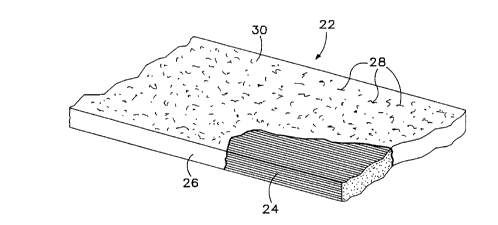
A preferred embodiment of the reinforcing panel
of the present invention is shown in FIG. 3a. The panel
22 comprises a plurality of synthetic fibers 24 that are
arranged parallel to one another and aligned with a
longitudinal direction of the panel. The fibers 24 are
maintained in their arrangement and alignment by a resin
encasement 26 that surrounds the fibers and fills the
interstices between the fibers. The panel 22 has been
treated, as described below, so that the surface areas 30
that will be adhered to the wood structure have exposed
fibers 28 to facilitate adhesion.
The parallel arrangement and longitudinal
alignment of the fibers 24 provides a panel having maxi-
mum strength because the strength comes from the fibers
(not the resin) and the configuration of fibers in the
present invention permits the maximum density of fibers.
Commonly, reinforced plastic parts have a fiber to resin
volume ratio of 40/60. However, the configuration of
fibers in the present invention permits fiber to resin
volume ratios as high as 60/40 when fabricated by the
' pultrusion method. Furthermore, the configuration of
fibers in the present im~ention facilitates wetting of
the fibers by the resin. In fabricating reinforced
plastic parts it is very important that the resin fully
impregnate the reinforcing fibers--this is known as
wetting. One hundred percent wetting is difficult to
WO 94121851 PCT/US94/03176
8
achieve with fibers configured ?n a complicated weave.
By providing a fiber configuration of parallel arrange-
ment, the present invention is able to achieve 100%
wetting even with high fiber to resin ratios.
Prior to the present invention, reinforced
plastic panels could be adhered to wood beams and struc-
tures by an epoxy adhesive only, which is more expensive
than the adhesives normally used in the preparation of
wood laminated products. A commercial grade adhesive
l0 that is frequently used in the preparation of laminated
wood is resorcinol, which is less expensive than epoxy
adhesives. By treating the surfaces of the reinforcing
panels 22 to cause the surface to hair up, wherein fibers
near the surface 30 are broken and the broken ends 28 are
caused to protrude from the resin encasement 26, there is
provided a heretofore unknown means for adhering a rein-
forced plastic panel to a wood structure by means of
nonepoxy adhesives.
The preferred method for causing the surface of
the reinforcing panel 22 to hair up is by sanding the
surface of the panel with 60 grit abrasive in a direction
transverse to the longitudinal direction of the panel.
The Sanding removes a small portion of the resin encase-
ment and exposes fibers that are closest to the surface.
Further sanding breaks individual fibers so that one end
of the fiber remains in the resin encasement and one end
of the fiber protrudes from the resin encasement
providing the hairy surface.
Alternative methods of hairing up the surface
of the panel 22 will be apparent to those skilled in the
art cf reinforced plastic fabrication and include chem-
ically treating the surface of the panel prior to curing
the resin encasement so as to cause voids in the surface
of the panel as it emerges from a curing die thereby
removing portions of the resin and exposing underlying
fibers. Another alternative method for causing the
surface of the panel to hair up is the use of broken
CA 02156417 1999-OS-26
9
rovings. As will be explained below, all the fibers
referred to herein are synthetic fibers and the fiber
manufacturing process first produces filaments which are
grouped together into strands or fibers which are further
grouped together into twisted strands, known as yarn, or
untwisted strands, known as rovings. Typically the
rovings or yarns are woven into a fabric for use in a
fabrication process. Ona type of roving that is avail-
able is referred to as a broken roving wherein the roving
l0 has been subjected to forces, which fray soma of the
individual fibers of the roving. By using the broken
rovings as a source of fibers to be aligned and encased
in the resin encasement, the panel which emerges has
surfaces which are haired up.
The panel shown in FIG. 3a is the preferred
embodiment of a panel to be used to reinforce the areas
of a wood beam 10 subjected to high tension stress.
Preferably, the fibers 24 would be aramid fibers or
carbon fibers. Aramid fibers are commercially available
as "I~ThAR," and the preferred grade for the present
invention is "~I,AR 49." Alternatively, the fibers
would bs a high modulus polyethylene which is sold
commercially as "SPECTRA" (Trade-mark).
An alternative embodiment of the reinforcing
panel is shown in FIG. 3b as a panel having two types of
fibers. A first fiber 30 is arranged parallel to one
another and aligned with the longitudinal direction of
the panel 22 as described above and a second fiber 31 is
arranged between the first type of fibers and a surface
32 that will be adhered to the wood structure. This
embodiment is most suitable for circumstances which
require a first fiber that will not hair up, such as
carbon or "SPECTRA." Carbon fibers alone are struc-
turally suitable for a reinforcing panel for a wood beam.
However, experimentation has shown that it is not possi-
ble to adhere the carbon fiber panel to the wood beam
with resorcinol adhesive and efforts to hair up the
71073-50
WO 94/21851 ~ -~ ~ j , , PCT/US94/03176
surface of the carbon fiber panel have proved ineffec-
tive. Thus, where it is desirable to use carbon or
"SPECTRA" as the first fiber 30, it has been found advan-
tageous to overlay the major surfaces of the panel with
5 aramid fibers as the second fiber 31, which are also
encased within the resin encasement 26. The use of
aramid fibers permits the panel to be haired up as
described above so that it may be adhered to wood beams
with nonepoxy adhesives such as resorcinol.
10 Another alternative embodiment is shown in
FIG. 3c as a panel having a first fiber 34 and a fiber
mat 35, both of which are encased in the resin encasement
26. This embodiment is most suitable for resin encase-
ments that are made of nonepoxy resins. Experimentation
with nonepoxy resin encasements has resulted in inter-
laminar shear failure in the reinforcing panel 22. Thus,
although the optimum configuration of fibers in the
reinforcing panel for maximum strength is parallel and
longitudinally aligned, the fiber mat 35 improves the _
interlaminar shear strength of the reinforcing panel 22
by providing fibers that are arranged oblique to the
longitudinal direction of the panel and thus resist
interlaminar strain.
Preferably, the resin 26 used in fabrication of
the panel is an epoxy resin. However, alternative embod-
iments could use other resins such as polyester, vinyl
ester, phenolic resins, polyimides, or polystyrylpyridine
(PSP). Alternative embodiments of the present invention
could use thermoplastic resins such as poly(ethylene-
terephthalate) (PET) and nylon-66.
The reinforcing panel of the present invention
provides a panel having an extremely high modulus of
elasticity in tension or in compression. However, the
reinforcing panel of the present invention has very
little lateral strength because substantially all fibers
are arranged parallel and aligned longit-.udinally. The
reinforcing panel is so weak transversely that a person
WO 94/21851 ~ ~ ~ ~ ~ ~ PCT/US94/03176
11
of average strength is able to bend the reinforcing panel
along its longitudinal axis to the point of breaking the
panel. A reinforcing panel of the present design is only
useful for reinforcing structures where the loads will be
unidirectional and of a direction that can be determined
and controlled.
Fabrication of the Reinforcing Panel
As discussed in the prior art, pultrusion is a
fabrication process wherein synthetic fibers are wetted
in resin and pulled through a heated die to cure the
resin which encases the synthetic fibers. All prior art
pultrusion fabrication processes use a substantial amount
of fibers aligned obliquely to the longitudinal axis of
the direction of the pull to provide lateral strength for
the pultruded product. In addition, prior art pultrusion
processes are carefully controlled to ensure sufficient
resin to prevent exposing any of the structural fibers.
Also, prior art pultrusion processes do not treat the
pultruded product in a way that would expose fibers
because it is well known in the reinforced plastics
industry that exposed fibers weaken the product and
cannot be used where it would be exposed to environmental
elements or people.
With reference to FIG. 1 the prior art
pultrusion process will be explained. The pultrusion
process shown in FIG. 1 is set up to fabricate a hollow
rectangular section member thus requiring a mandrel 40 to
maintain the hollow core during the pultrusion process.
To fabricate a solid member, the prior art pultrusion
process would be modified by eliminating the mandrel 40.
The prior art pultrus~or. process comprises upper and
lower mats 44, 45 respectively, that ars typically woven
rovings or woven fabric. There is also a plurality of
rovings 46 that may be longitudinally aligned with the
structural member being formed and are sandwiched between
the woven mats. Fuller 48 provides the force that pulls
the fibers through the process. Thus, beginning with
WO 94/21851 PCT/US94/03176
215~~~~
12
lower woven mat 44, the mat is nulJ_ed through a resin
bath 50 and formed around mandrel 40 by forming die 52.
The rovings 46 are likewise wetted in a resin bath 54 and
formed around the mandrel/mat combination by forming die
56. Thereafter, upper woven mat 45 is wetted in a resin
bath 58 and formed around the combination of the mandrel
40, lower mat 44, and rovings 46 by forming die 60.
Thereafter, the entire combination is pulled through
heated die 42 which cures the resin so that the struc-
tural member 38 emerges from the die as a rigid member
38.
The present invention improves upon the
pultrusion process of the prior art for the purpose of
fabricating the reinforcing panel 22 (or 23) of the
present invention. Beginning with a plurality of bobbins
70 having synthetic fiber rovings 72 thereon, the rovings
are pulled through a card 74 for alignment and to prevent
entanglement of the rovings. The card 74 has a plurality
of openings 76 through which the rovings 72 pass. The
openings 76 are typically gasketed wii.h a low friction
material such as a ceramic or plastic to prevent any
abrasion or resistance to the rovings 72 from the edges
of the openings. After the rovings 72 pass through the
card 74, the rovings are gathered and arranged parallel
to one another by a first comb 78. After the first comb,
the rovings pass over a tensioning mandrel 80 and under a
second comb 82 which further maintains the parallel
arrangement of the rovings 72. Thereafter, the rovings
are wetted in a resin bath 84 and gathered by a forming
die 86 prior to entering a heated die 88 having an
orifice 90 that shapes the panel 22 (or 23). Heat from
the die 88 cures the resin so that the panel which
emerges is a substantially rigid member.
The prior art pultrusion process was considered
desirable for fabricating continuous lengths of rein-
forced plastics. However, by pultruding reinforcing
panels of the present invention an unexpected benefit was
WO 94/21851 w
PCT/US94I03176
13
realized because of the ability to arrange the fibers
substantially parallel to one another and aligned with
the longitudinal direction of the reinforcing panel. An
additional unexpected benefit of the improved pultrusion
process of the present invention was the tensioning of
the fibers while the resin was cured which provides two
benefits. First, the tension in the fibers assists in
maintaining the parallel arrangement and alignment of the
fibers within the panel. Second, by curing the resin
while the fibers are under tension it was found that the
resulting reinforcing panel was more rigid and subse-
quently there was less deflection upon an initial loading
of a wood beam reinforced by a reinforcing panel of the
present invention. By curing the resin while the fibers
were under tension the initial strain of the fibers was
set during the fabrication process and, accordingly, when
the reinforcing panel was adhered to a wood beam and the
beam was loaded, there was less deflection than in beams
using reinforcing panels made of fibers that were not in
tension during the resin cure.
Experimentation has shown that the optimum
tension in the fibers during the resin cure is approxi-
mately three to eight pounds. The fiber tension force is
created by a back pressure on the rovings which may be
accomplished by the tensioning mandrel 80 in combination
with the combs 78, 82 or by the use of friction bobbins
70 wherein the rotational friction of the bobbins may be
adjusted to provide the desired back pressure on the
rovings.
The terms and expressions which have been
employed in the foregoing specification are used therein
' as terms of description and not of limitation, and there
is no intention, in the use of such terms and expres-
sions, of excluding equivalents of the features shown and
described or portions thereof, it being recognized that
the scope of the invention is defined and limited only by
the claims which follow.