Note: Descriptions are shown in the official language in which they were submitted.
WO 94/18888 ~ ~~ PCT/US94/01885
-1-
Description
Surgical Extractor
Technical Field
This invention generally relates to medical
instruments and more specifically to an extractor for
removing an object from a body, particularly calculi that
can form in the biliary and urinary systems.
Background Art
Recently developed medical instruments reduce the
invasiveness and potential trauma previously associated
with various medical procedures. The removal of calculi
in the form of kidney stones, gallstones and the like from
the body is one area where this effort is meeting with
success. Various instruments now permit the removal of
kidney stones and gallstones without the need for major
surgery.
Some of these instruments incorporate miniaturized
grasping forceps. This invention, however, is directed to
an alternative set of instruments that utilize mechanical
retrieval baskets as described in the following United
States Letters Patent:
4,590,938 (1986) Segura et al
4,611,594 (1986) Grayhack et al
4,625,726 (1986) Duthoy
4,807,626 (1989) McGirr
The Segura et al patent discloses a medical retrieval
device that can be inserted through the working channel of
an endoscope for removing stones and the like from the
kidneys or the ureter or biliary duct. It includes a
retrieval basket of relatively large diameter that is
extendable from the distal end of a sheath and collapsible
when withdrawn into the sheath. Outwardly bowed spring
strips form the retrieval basket. These strips extend
generally axially of the sheath and join at respective
distal and proximal ends. The retrieval basket has a
generally bulbous form which is relatively stiff due to
WO 94/18888 PCT/US94/01885
-2-
the spring strip construction and facilitates dislodgement
and capture of stones.
The Grayhack et al patent discloses another retrieval
basket that is useful during the removal and/or '
destruction of calculi. A smooth outer tubular sheath
overlies and contains a stranded wire cable terminating in '
a protective tip at the,working or distal end of the
device. When the cable is extended distally, the spring
wire strands at the working end of the cable expand to
form a retrieval basket. The distal end of this device
additionally includes an expandable distal portion for
protecting surrounding tissue during withdrawal of the
device and calculi.
The Duthoy patent discloses an extraction device that
includes a retrieval basket formed from a plurality of
wires spaced about and outwardly from ark imaginary
extension of the center line of a hollow cable. A
filiform extends distally from the distal end of the
retrieval basket to extend past a stone and to allow the
basket to be threaded around and onto the calculi.
The P~IcGirr patent discloses an extractor included a
self-closing retrieval basket at the distal end of a
catheter with a flexible control line for opening the
basket from the proximal end of the catheter. The basket
assumes a normal position wherein it is in a compact
closed form. Pulling on the control line flexes the
strips to open the basket. When the control line is
released, the strips relax and surround the calculi or
object being removed.
These and other surgical extractors using retrieval
baskets have certain common characteristics. Each
retrieval basket comprises a plurality of strands in the t
form of individual strips or wires substantially
equiangularly spaced about the retrieval basket. In some
retrieval baskets the strands are formed along
substantially straight lines when the basket is in a
compact form; in others, the individual strands extend
along a generally helical path. Each instrument includes
WO 94/18888 ~ ~ ~ PCT/US94/01885
-3-
a plurality of three or more strands. However, the
overall size or diameter of an extractor and ancillary
equipment, such as an endoscopic device, can impose upper
limits on that plurality. For example, an instrument
having a sheath outer diameter of 3.0 Fr can incorporate
up to 6 wires each having a diameter 0.008 inches in the
prior art.
Additional wires could be advantageous because
increasing the number of wires increases the number of
contacts between the basket and any entrapped calculi.
However, the overall size limitation means that additional
wires can be incorporated only by decreasing their
diameters. As the individual diameters reduce, they
become weaker. Moreover the individual wires are
generally equiangularly spaced, so the additional wires
reduce the angular spacing between adjacent wires. This
can complicate the manipulation of an expanded retrieval
basket onto calculi. Wires of reduced diameter can also
limit any radially acting, dilating force that the wires
exert against surrounding tissue when the retrieval basket
expands. In some applications the retrieval basket may
not fully open. This attribute can reduce the opening
between adjacent wires and make it more difficult to
entrap calculi. Even prior art extractors with larger
single wires can fail to expand fully with the same
result.
Disclosure of Invention
Therefore it is an object of this invention to
provide a surgical extractor that increases the
reliability of retaining calculi in a retrieval basket.
Another object of this invention is to provide a
surgical extractor that increases the number of contact
points with calculi in a retrieval basket without
increasing the overall size of the instrument.
Still another object of this invention is to provide
a surgical extractor that increases the number of contact
points with entrapped calculi without reducing the
CA 02156517 2001-03-05
74611-13
4
dilating force that can be extractor can apply to surrounding
tissue.
Yet another object of this invention is to provide a
surgical extractor that increases the number of contacts with
entrapped calculi in an extractor and that opens fully when
expanded.
Yet still another object of this invention is to
provide a surgical extractor that increases the number of
contacts with entrapped calculi in an extractor that is readily
manufactured.
Still yet another object of this invention is to
provide a surgical extractor that increases the number of
contact points with entrapped calculi and requires
substantially the same level of physician dexterity as required
by prior art extractors having a fewer number of such contact
points.
In accordance with this invention there is provided
in a surgical extractor for removing an object from a body
including a plurality of threads normally encased in a sheath
and wrapped in a helical form whereupon displacement of a
portion of the threads from the sheath enables the portions of
the threads to become relatively widely angularly spaced to
form a basket with distal and proximal ends for retrieving an
object, the improvement wherein each thread comprises a
plurality of individual filaments that are closely angularly
spaced throughout the length of the basket relative to the
spacing of adjacent threads upon the displacement of the
portions of the threads from the sheath.
The invention also seeks to provide a surgical
extractor for removing an object from a body comprising: a
CA 02156517 2001-03-05
74611-13
4a
handle extending along an axis at a proximal portion of said
extractor for operating said extractor, said handle having a
base for being grasped by a physician and a slider for
reciprocating along the axis with respect to said base; a
basket forming means connected to said base for forming a
basket distally of said handle, said basket forming means
including a plurality of sets of filaments being helically
wound with each of said sets of filaments constituting a turn
in a helix, and each of said sets of filaments comprising a
plurality of individual, closely angularly spaced filaments
that are prestressed in a distal portion thereof for forming an
enlarged basket; and a sheath connected to said slider and
axially displaceable between first and second positions with
respect to said basket forming means whereby said sheath
retains said filaments in a compact form within said sheath in
a first position and exposes the distal portion of said basket
forming means in the second position thereby to enable said
prestressed filaments to form the enlarged basket with each of
said sets of filaments throughout the length of said enlarged
basket being relatively widely, angularly spaced from adjacent
ones of said sets of filaments and said filaments in one of
said sets remaining closely angularly spaced throughout the
length of the basket relative to the angular spacing of
adjacent sets of filaments.
The invention also seeks to provide a surgical
extractor for removing objects from a body comprising: a molded
plastic, partially hollowed base extending axially; a support
including a solid stainless steel radially flexible, axially
stiff rod attached to said base and extending distally
therefrom, a stainless steel cable extending distally from said
rod and means for connecting said rod and said cable together
axially; a plurality of strands comprising a plurality of pairs
of spaced stainless steel wires attached to the distal end of
CA 02156517 2001-03-05
74611-13
4b
said cable and including means for defining proximal and distal
portions of said wires, said strands in said distal portion
being formed to conform to a helix having a greater diameter
than said proximal portion and each of said strands being
equiangularly spaced with individual wires in each of said
strands being closely angularly spaced; a plastic slider
captured in said base for limited axial movement relative
thereto between distal and proximal positions; and a polyimide
sheath of a given diameter having a proximal end attached to
said slider for overlying said support and said strands, said
slider, in its distal position, locating said sheath
coextensively with said distal portion of said strands thereby
to compact and retain said strands at substantially the given
diameter and, in its proximal position, retracting said sheath
to release said strands to form an enlarged retrieval basket
for entrapping the object intermediate proximal and distal ends
of said basket with adjacent ones of said strands extending
between the proximal and distal ends of the basket being
relatively widely angularly spaced and individual wires in at
least one of said strands being relatively closely angularly
spaced between the proximal and distal ends of the basket.
Brief Description of the Drawings
The appended claims particularly point out and
distinctly claim the subject matter of this invention. The
various objects, advantages and novel features of this
invention will be more fully apparent from a reading of the
following detailed description in conjunction with the
accompanying drawings in which like reference numerals refer to
like parts, and in which:
CA 02156517 2001-03-05
74611-13
4c
Fig. 1 is a plan view of a surgical extractor
constructed in accordance with this invention with a handle at
a proximal end and an expanded retrieval basket at a distal
end;
WO 94/18888 ~ ~ ~ PCT/LJS94/01885
-5-
Fig. 2 is a enlarged plan view of the distal end of
the extractor shown in Fig. 1;
Fig. 3 is an enlarged view, partially in cross
section, of the distal end of the extractor shown in Figs.
1 and 2 in a compact form
Fig. 4 depicts the distal end of a surgical extractor
incorporating a different embodiment of a retrieval
basket;
Fig. 5 depicts the distal end of another surgical
extractor with still a different retrieval basket;
Fig. 6 is an enlarged plan view of the handle at the
proximal end of the extractor shown in Fig. 1; and
Fig. 7 is another view, partially in section, taken
along lines 7-7 in Fig. 6; and
Fig. 8 is a cross sectional view taken along lines 8-
8 in Fig. 7. a
best Mode for Carryina out the Invention
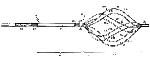
Fig. 1 depicts one embodiment of a surgical extractor
10 constructed in accordance with this invention. The
surgical extractor 10 includes a handle 11 at a proximal
end 12 having a base 13 and a slider 14. A physician can
grasp the base 13 in the palm in his or her hand and
manipulate the slider 14 with his or her thumb. A
retrieval basket 15 constructed in accordance with this
invention is located at the distal end 16 of the extractor
10. A sheath 17 overlies an intermediate supporting
structure between the handle 12 and the retrieval basket
15.
As shown in Fig. 1 the slider 14 is located at a
proximal position. When the slider 14 advances to a
distal position, that is to the right in Figs. 1 and 2,
the sheath 17 advances to compact and cover the retrieval
basket 15 as shown in Fig. 3. The sheath 17 typically
comprises a polyimide tube or a tube of another material
that exhibits the radial flexibility, axial stiffness,
biocompatability and hoop strength of a polyimide tube.
WO 94/18888 - PCT/US94/0~885
-6-
Fig. 2 depicts the distal end 16 of the surgical
extractor 10 in an enlarged form and specifically
discloses a substitute for a prior art four-wire retrieval
basket. The retrieval basket comprises a plurality of '
four prestressed strands 21, 22, 23 and 24. In accordance
with this invention, each of these strands comprises a '
plurality of individual wires. The strand 21, for
example, comprises wires 21a and 21b; the strand 22, wires
22a and 22b; the strand 23, wires 23a and 23b and the
strand 24, wires 24a and 24b. These wires will be made
from stainless steel or some other shape memory material.
A cap 25 captures distal ends of all the wires 21a
through 24b by soldering the wires in the cap 25, by
swaging or by some other method. A sleeve 26 at the
proximal end of the basket 25 encircles and is affixed to
the wires. The cap 25 and sleeve 26 thereby define the
axial extent of the retrieval basket 15 in which the
individual wires are prestressed or preformed to the
helical expanded shape show in Figs.l and 2. Portions of
the individual wires, such as wires 21a and 21b, extend
proximally of the sleeve 26 to a connector 27 inside the
sheath 17. These portions extend essentially axially
between sleeve 26 and a connector 27 and within the sheath
17.
Consequently, the structure shown in Fig. 2 produces
a retrieval basket 15 in a distal portion 30 of the wires
21a through 24b and a proximal portion 31 intermediate the
sleeve 26 and connector 27. Each of the wires lies in
parallel in the proximal wire portion 31, and each of the
wires is independent in the distal portion 30.
Therefore, the distal end 16 of the extractor 10 remains
rad~ally flexible and, by virtue of the sheath 17, axially
stiff to facilitate placement of the extractor 10. The
combination of radial flexibility and axial stiffness is ,
particularly important when the extractor 10 has the form
shown in Fig. 3 with the sheath 17 advanced distally to
the cap 25.
WO 94/18888 ~ PCT/US94/01885
_7_
More specifically, a physician will introduce the
extractor 10 with its distal end 16 in the form shown in
Fig. 3. In this form the sheath 17 retains the distal
wire portion 30 in its compact form and stresses the
individual wires. When the extractor 10 is positioned
proximate to calculi to be retrieved, the physician uses
the slider 14 in Fig. 1 to retract the sheath 17 and
expose the wires in the distal wire portion 30. With the
constraint of sheath 17 removed, the wires return to their
original shape as shown in Fig. 2 thereby to dilate
surrounding tissue and to provide a structure that can be
manipulated over the calculi. Once the physician has
moved calculi into the retrieval basket 15 defined by the
strands 21 through 24, the physician advances the sheath
17 distally and reduces the volume of the retrieval basket
15 until it contacts the entrapped calculi. Then the
physician withdraws the extractor 10 with the entrapped
calculi.
During manufacture of the specific embodiment of Fig.
2, eight individual wires 21a through 24b are collected
together. The distal ends of the wires are soldered or
swaged into the cap 25. The wires are separated into
pairs corresponding to the strands 21 through 24. Each
pair is then formed onto a four-part helix former.
Although the wires in a strand, such as wires 21a and 21b
associated with strand 21, are formed as a pair of a
single strand or thread, the wires are not twisted.
Consequently, each of the strands 21 through 24 will be
equiangularly spaced, by approximately 90°, but individual
wires, such as wires 21a and 21b of a strand, such as
strand 21, will be closely angularly spaced. A typical
close angular spacing will produce a separation of the
wires in a set, such as wires 21a and 21b, by a distance
in the range from 0 to 0.5 mm or so.
The increase in the number of wires does not reduce
the openings between adjacent strands appreciably, so the
effort for moving the retrieval basket 15 over calculi is
about the same as required to position a prior art four-
WO 94/18888 PCTII1S94/01885
_g_
strand basket. The sleeve 26 provides a confining force
that allows the proximal portion 31 of the wires to lie in
a substantially parallel entrusted relationship between
the sleeve 26 and connector 27. The manufacturing process '
also prestressed the individual wires 21a through 25b into
the helical form shown in Fig. 2. '
The use of multiple wires for a given strand, such as
wires 22a and 21b in strand 21, increases the number of
contact points with any entrapped calculi. In Fig. 2, for
example, eight wires will contact the calculi rather than
four. Moreover, the close equiangular spacing of adjacent
wires in a given strand also permits the wires
collectively to accommodate any surface unevenness of such
calculi surfaces to further increase the reliability with
which the retrieval basket 15 entraps calculi.
Further, the increase in the number of wires, such as
doubling the wires from four to eight in Fig. 2, occurs
without increasing the overall size of the sheath 17 or
reducing the strength of the retrieval basket 15. For
example, it is possible to replace four individual wires
having a diameter of 0.008" in a sheath 17 with an outside
diameter of 3.0 Fr with eight wires having a diameter of
0.006" due to the change in packing efficiency without a
concomitant reduction in the diameter. Thus, for a given
material, the collective strength of the retrieval basket
15 and of the strands 21 through 24 can increase by as
much as 50~ over a single-filament strand of the prior
art.
When the sheath 17 moves from the position shown in
Fig. 3 to the position shown in Fig. 2 and releases the
retrieval basket 15, the retrieval basket 15 can exert the
same or a greater dilating force on surrounding tissue as .
produced by a corresponding prior art device with half of
the wires. Thus, the reduction in the wire size and the ,
doubling of the number of contacts with entrapped calculi
occurs without affecting the overall strength and
reliability of the extractor 10.
WO 94/18888 ~ ~ ~, PCT/US94/01885
_g_
Fig. 4 depicts an alternative embodiment of a
retrieval basket 15A and sheath 17A at a distal end 16A of
the extractor 10A. In this particular embodiment, the
retrieval basket 15A comprises three strands 41, 42 and
43. Each 'strand, again, includes a pair of wires or
filaments. For example, the strand 41 includes wires 41a
and 41b. A cap 25A captures the distal end of the strands
41, 42 and 43 and another sleeve connector A sleeve,
corresponding to sleeve 26, defines the proximal end of
the retrieval basket 15A. In this particular embodiment
the strands 41, 42 and 43 would be angularly spaced by
about 120°.
In this particular embodiment, the sleeve connector
25A also carries a filiform 44 that extends distally from
the retrieval basket 15A. Such filiforms are know in the
art. Fig. 4 illustrates the use of a filiform in
appropriate circumstances; a filiform can be included as
an element in any embodiment of this invention.
Fig. 5 depicts another embodiment of a surgical
extractor 10B that includes a retrieval basket 15B at a
distal end 16B and a sheath 17B. In this particular
embodiment the retrieval basket 15A comprises five
substantially equiangularly spaced strands 51 though 55.
Each strand comprises a pair of wires or filaments, such
as wires 51a and 51b that form strand 51, and forms a
portion of a turn of a helix. An end cap 25B retains the
distal ends of the wires that form the strands 51 through
55.
As previously indicated with respect to Fig 1, the
sheath 17 extends between the handle 11 and the distal end
16 and contains an interconnecting link that allows the
slider 14 to move the sheath 17 relative to the distal end
16. This link comprises a radially flexible stainless
steel cable 60 that is shown at its distal end in Figs. 2
and 3, and at its proximal end in Figs. 6 and 7. The
sheath 17 retains the cable 60 on its axis.
Now referring to Figs. 6 through 8, the proximal end
of the cable 60 attaches to a rod 61 by swaging, soldering
WO 94/18888 PCT/US94/01885
-10-
or other method. The rod 61 extends proximally into the
handle 11.
More specifically, the handle base 13 includes a
hollowed handle portion 62 with an internal boss or
receptacle 63 that receives the proximal end of the rod
61. Typically the proximal end of the rod 61 will be
affixed in the receptacle 63 by an adhesive, ultrasonic or
other fastening technique. Consequently, the rod 61, the
cable 60 and the basket 15 are fixed spatially with
respect to the handle 11.
The slider 14 rides in an axially extending chamber
64 within the base 13 formed with a radially extending
slot 65. The slider 14 comprises a cylindrical, elongated
body 66 that has a radial passageway 67 for allowing the
cylindrical body 66 to slide axially and freely in the
chamber 64 with respect to the base 13 and the rod 61.
A thumb actuator 70 includes a thumb pad 71 and
radial arm 72 that are molded integrally with and extend
radially from the cylindrical body 66. The arm 72 extends
through the slot 65 and is therefore slidable along the
axis of the extractor 10 between distal and proximal
positions. In this particular embodiment the base portion
11 includes radially extending bosses 73 and 74 that
define the proximal and distal terminations of the slot 65
respectively. The slider than moves between a proximal
position, defined when the arm 72 reaches the boss 73, and
a distal position defined when the arm 72 reaches the boss
74.
The distal end of the cylindrical body 66 supports a
Luer-lock fitting 75. A first component or base 76
attaches to the cylindrical body 66 and includes an
axially extending aperture that allows the rod 61 to pass ,
through the fitting 75. A detachable component 77 carries
the sheath 17. Consequently, as a physician moves the ,
thumb actuator pad 71 between proximal and distal
positions, the slider 14 and the sheath 17 move relative
to the rod 61, the cable 60 and the retrieval basked 15
(Fig. 1). Further as the thumb pad 71 moves toward the
WO 94/18888 PCT/US94/01885
-11-
distal position, the distal end of the sheath 17, as shown
in Figs. 2 and 3, advances over and compacts the strands
21 through 24 of the retrieval basket 15 due to the axial
' stiffness and hoop strength of a polyimide tube or tube of
similar material.
Therefore, each embodiment disclosed in Figs. 1
through 8 provides an extractor that meets the various
objects of this invention. The extractor requires
essentially the degree of dexterity as would be involved
with a prior art extractor. In each embodiment the use of
strands having multiple, closely adjacent, independent
wires formed to be closely adjacent increases the number
of contact points with an entrapped calculi without
requiring a concomitant increase in the size of the
overlying sheath or in the difficulty placing the
retrieval basket over calculi. Thus the extractor with
multiple wire strands does not subject patient to any
increase or trauma during its introduction into the body.
Moreover, this is accomplished without affecting the
strength and reliability of the retrieval basket.
This invention has been described with respect to
specific embodiments constructed with specific materials.
Other materials can be substituted for various components.
The interconnecting structure between the retrieval basket
at the distal end of the extractor and the handle can be
modified. Different numbers of strands and different
numbers of wires or filaments in a strand may be
incorporated in an extractor. It also will be apparent
that many other modifications can be made to the disclosed
apparatus without departing from the invention.
Therefore, it is the intent of the appended claims to
cover all such variations and modifications as come within
the true spirit and scope of this invention.