Note: Descriptions are shown in the official language in which they were submitted.
2156547
Case: 6064
RAILCAR TRUCK BEARING ADAPTER CONSTRUCTION
Bac~l-~u"d of the Invention
Field of the Invention
The present invention relates to a bearing adapter assembly for a railcar truck. More
5 ~ecirlcally, tightly secured bearing adapters f~y hold the axle bearing in position to avoid
angling and lateral axle variation, and the resll1t~nt truck "wal~ing". Past l~,sear~h has illustrated
railcar truck ~.a~ g induces truck hllntin~ during railcar travel, which wal~ing causes undue
wear on rails and wheels as well as h~asil~g fuel usage.
Descriplion of the Prior Art
In a three-piece railcar truck assembly, the side frames and bolster are generally square,
that is the axles and bolster are appro~hl~tely parallel to each other, and the side frames are
parallel to each other but normal to the axles and bolster. After truck assembly and at certain
Milcar speeds, the truck may become ~ly~ lly unstable, which may be loosely defined as truck
l,...,1;n~. Truck l.~ is defined in the Car and Locomotive Cyclopedia (1974) as "an instability
15 at high speed of a wheel set (truck), causing it to weave down the track, usually with the (wheel)
flanges strikin~ the rail." Truck hllntin~ has been the subject of many past and Ol1gOil~g l~sealch
efforts within the rail i~.lu~ by truck suppliers, car builders and railroad lines, as this condition
is u~desilable from both operational and safety considerations. Past ~seal~;h efforts have noted a
si~.ir.~ relationship ~t~n truck ~al~ing and reslllt~nt truck hllntin~. These l~se~ch efforts
20 and some of their conclusions are ~ ~l in the ASME paper, "Truck ~llntin~ in the Three-
Piece Freight Car Truck" by V. T. Hawthorne, which paper in-~hl~ olical l~,f~.e.~ce to still
earlier l~,se~.,h in this field. One of the earlier rcsedlch.,.~ noted "...that in the empty car the
higher column fo~e of the co~l column d~llph~g provides a greater warp slirrll~ss and,
con~luently, yields a higher critical (truck) hllntin~ speed." The ASME paper desclil~d a project
25 that was ~lesi~od to ~ as~l-. the following p~ll~t~ warp sl;rr~ss; lateral d&ll~hlg force; and,
lateral spring rate.
The warp ~l;rr.,~ss results in this Hawthorne project duplicated earlier test results and it
was noted that as the warp angle h~ ,a~d to 1~(60 ~ s) of angular di~pl~~e~ the warp
-1-
2156547
irr.~cc dropped off app-~cciably. Further, it was noted that earlier warp ~lirr~Pss data showed
that 1 ~ of displ~ r~l~se,lLed the m~ximllm warp travel of a relatively new truck during
l....~l;.~g. Th~fo~, at warp angles prevalent in truck hnnting, the warp ~lirr..~ss fell considerably
below the values n~cess~. ~ to raise the critical speed of hllntin~ above the normal ~c,aling range
5 of the freight railcar.
A field test noted that a new railcar truck lun~ g at a speed above 60 miles per hour with
track inputs c~lsin~ warp angles below 0.3~ would not be expected to hunt. However, if the warp
angle suddenly became 1.0~ due to a track irregularity, it is exrected that the critical truck hlmting
speed of the railcar would drop to about 52 miles per hour and i~r~ e~t truck l~ would
occur. - -
A three-piece railcar truck generally allows a considerable amount of relative movement
~Lweell the wheel and axle asselllbly, or the wheelset which in~ludes the axle, wheels and the
be~rin~, and the sul)po~ lg side frame at the side-frame pedestal jaw. This may be due to
m~mlf~r*lring tole.ances pe~ *d in the various col~oll~ , that is the side-frame pedestal jaw
15 and bearing adapter, and to the form of the connection for the bearing adapter, the journal end of
the wheelset and the integral jaws of the side frame ~llu ;tUl~,. U.S. Patent No. 3,211,112 to
Baker discloses an as~,llbly to damp the relative lateral m~velll~ the wheel and axle
assembly, and the ~CcQCi~tpd side frame. More s~cirlcally, a resilient means or lll~,llbel is
provided ~l~ ,n the top of the journal end of the wheel and axle assembly, and the associated
20 side frame ...~ n~r to p~(nluce val~ing frictional forces for da llpillg the relative movelllc,ll
b~.~.,ell the assembly and the side frame. The Baker-' 112 patent recognized the ul~deshdbility of
g track ~.lulbalions through the wl.~elcet side frames and bolsters, but inhibition of
this force ll~ ...icsion is i..~ Aed to be accollll)lished by d~ing the di~lulballces caused by the
lateral axle m~ , not by supple~i,ing their initiation.
In U.S. Patent No. 3,274,955 to Thomas and also in U.S. Patent No. 3,276,395 to
Heintzel, a roller bearing adapter is illu~ ted with an el~ctomer on the upper part of the cap
plate, which adapter is positioned in the side frame pedestal jaw with the elas~olll~ w~n the
pedestal roof and the adapter for relieving exposure to high stresses. A similar concept is shown
in U.S. Patent No.-3,381,629 to Jones, which provided an cl~ lO". ,ic material bcl~en each
bearing assembly and the pedestal roof to ~ccQrnm~?te axial movcll*ll~ of the bearing assemblies
of each axle and to alleviate lateral impact to the side frame.
21~ 65~ 7
Other means have been utilized for mA;~IAinill~ a truck in a square or parallel relationship.
In U.S. Patent No. 4,103,623-Radwill, friction shoes are provided to frictionally engage both the
side frame column and bolster. This friction shoe allange~lent is intended to increase the
lei,llai~ g moment, which is e~ Led to result in an illcleascd truck hllntin~ speed. The friction
S shoes had contact sllrf~ces with some appropliale m~mlfa~ rin~ tolerance to control initial contact
areas to develop a m~ximllm l~,i,llainillg moment.
U.S. Patent No. 4,192,240 to Korpics provided a wear liner against the roof of a side-
frame pedestal jaw. The disclosure recognized the detrimental effects of having a loose wear liner
in the pedestal jaw. Wear liners are provided against the roof of the pedestal jaw to reduce wear
10 in the roof caused by oscillating motions of the side frame relative to the wheel-axle assembly and
the bearing. The disclosed wear liner inrlllded upwardly projecting tabs to grip the roof and side
frame to inhibit lon~itll~in~l mov~ of the wear liner, and do~vllwardly projecting legs to
coopela~ with the pedestaljaw stop lugs to inhibit lateral movelll~ of the wear liner relative to
the roof. The stop lugs of the pedestal jaw are positioned on opposi~ sides of the depe~ legs
15 of the jaw, which lugs are engageable with the dOwllwaldly d~ .ii"~ wear liner legs.
U.S. Patent No. 3,621,792 to Lisch provides a pedestal jaw opening with uulw~'~ly sloped
sidewalls and a bearing adapter with sloped sidewalls positioned in the jaw o~.~ing. An
e~ c.,..- lic is positioned ~h~,en the adapter and the pedestal sidewall and roof, which elz~lc".~fr
provides les;~i~An~e in colll~ssion and yieldability in shear, and ~rfi~ri~ softness for cushioning.
20 It is noted that by posilioning the elasl~ pad bdween all the i,lte.r~ces of the adapter and the
pedestal jaw, metal-to-metal contact is pl~,~,ented along with wear and L~ ion of noise and
vibl~lion from the track to the truck rl~ing. Similarly in U.S. Patent Nos. 3,699,897 and
4,416,203 to Sherrick, a resilient pad is provided ~t~en the bearing adapter and the side frame.
In U.S. Patent No. 4,072,112 to Wiebe, an elaslolll~"ic positioning means is placed
25 il-t~ * the bearing carrier and one of the pedestal jaws to bias the bearing carrier into direct
co-~ ion or Cl~,Ag. ~~ with the opposite pedestal jaw to limit relative angular mov~lll~,ll
and linear ~ en~ of the wheel set to the side frame.
U.S. Patent No. 4,108,080 and 4,030,424 to Garner et al. teach a rigid H-frame truck
ass~ ~bly having resilient journal pads in the pedestal jaws. The truck provided by this
development delllol-~hA~*d illl~loved riding c~ct~ lics. Similarly U.S. Patent Nos. 4,082,043
~156s47
and 4,103,624 to Hqmmonds et al. disclose an integral H-frame truck with resilient elements in
the journal beali~s.
In U.S. Patent No. 4,242,966 to Holt et al., a railcar truck has a ll~lsolll with a pair of
tubes rigidly co~ cled bc~en the longih~-lin-q-lly e~ in_ side frames. The transom allows
S vertical movclllcll~ of the side frames but resists lon_il~1-1inq1 displacement of the side frames with
respect to each other.
U.S. Patent No. 4,841,875 to Corsten et al. provides a suspension all~1gclllellt with at
least two annular elas~ ic shock absoll,e.~ having an op~ ulll adjustability in the lon~ib-din
and ~ ,.,.se directions of the vehicle.
~ ivc means for the insertion and se~. ;u_ of a wear liner against a pedestal jaw roof
are taught in U.S. Patent Nos. 4,034,681 and 4,078,501 to N~ nl- et al. and 4,192,240 to
Korpics, which patents have a common qC~ign~e. The objeclive of these patent disclosures was to
provide illl~)loved means for se~ _ a wear liner in the jaw to ~in;.~ its movement and to
improve the assembly means. The wear liners are provided with d~wllwaldly depelldhlg legs and
stop lugs posilioll~d to inhibit movclll~.ll of the wear liner, such as in the lateral direction relative
to the roof.
U.S. Patent No. 4,428,303 to Tack illustrates a clip-on pedestal wear plate especially
. l-qpted for worn pedest-q-l ~ulr~ces. A pair of wear plates, or a single mpmher with a central
portion of the plate removed, may be used to provide the structure of the invention.
All of the above disclosed a~p~lus disclose a journal asselllbly or an assembly for a
railcar truck axle end, which ass_lllbly is operable in the pedestal jaw, and the disclosures
recognized the desirability of k~ping the truck side frames aligned with each other to avoid truck
l....n;up. However, the several ~ clQsllres provided a plurality of resilient means or structures in
the pedçst~l jaw and around the axle journal bealhlgs, but none of the s~ ;lul. s addressed the
25 problem of l~ the bearing adapter and con~equçntly the axle and side frames in their
aligned positionc._ Several of the above-noted r~f~ ces specifically utilized e~ or
resilient com~ol~ in the ped~Pst~l jaw or in associalion with the journal bearing to acc~.. ~l~te
the di~lulbal~ces and flexing motions cA~.ic.lced by the axles and side frames.
215~547
SUMMARY OF THE INVENTION
A side frame for a railcar truck has peclest~ at both of its longit~ in~l ends with jaws to
receive the journal ends of the axle shafts. These journals are generally provided with bea~ gs,
which are secured in bearing adapters positioned in the pedestal jaws with the intent that the axles,
5 usually two, of the truck remain aligned and parallel during railcar travel. The above-noted
bearing adapters are generally secured in the pedestal jaw by mating a recess in the bearing
adapter with thrust lugs protruding from the side frame peclest~l, which are m~int~in~l in this
interlocked mating by the railcar weight. In addition, wear plates are frequently positioned
b~ . en the adapter and the pedestal jaw roof to ...i~ e wear from the l~ ~ flexing of the
10 adapter in the jaw during railcar travel. The present invention provides a bearing adapter
angularly secured against the roof of the side-frame pedestal jaw, which adapter accolll...odates the
journal bearing on the axle end. The adapter is provided at an acute angle to both the hol~ontal
and vertical side-frame axes to bear against the thrust lugs to more positively ~,a~.r~ l the wal~ing
loads to the side frame to ...in;...i~e the flexural displ~ç~ in the jaw and bearing to more
15 na.lowly limit the lateral displ~ ~ n~n~ of the axle and side frame assemblies to reduce railcar
truck wal~ g and the con~ çnt truck hnntin~. Such an integral jaw and bearing assembly
il~c~ases warp ~ n~e and l~luces the angular displ~rem~nt under moderate ~al~ing loads
below 1~ and in a p,ef~ ,d embodiment is less than 0.35~. It is recognized that truck hnntin~ is
not eli...in~led per se, but the i-lcleased ~s~ e to wal~ g results in reduced angles of lateral
20 displ~ ç.n~.~l The con~.l~ent critical speed, where truck hllntin~ occurs, is h~cl~,ased beyond the
normal ope.aling speed of the railcar. In an ~lt~rn~tive embo~lim~ont a wear plate is secured into
the pedestaljaw roof at a desired acute angle and the bearing adapter is secured in the pedestal
jaw against the wear plate at the appropliale angle and against the thrust lugs to again .ni~-;.ni~
the frequency of vilJ~alion and to posilively llalisfe,~ the vibrational load to the side frame at a
25 n~ ;n,~... warp angle ~t~n the axle and side frames.
BRIEF DESCRIPIION OF THE DRAWINGS
In the figures of the Drawing, like l~,f~ ce numerals identify like co",pol~e,lts and in the
~awillgS:
Figure 1 is a plan view of an exe",pl~ rail truck bolster and side frame assc.l,bly;
-5-
~1$6547
Figure lA is an elevation view of a side frame with its pedestal jaw oull~ed against Mil
wheels;
Figure 2 is an enlarged elevation view in partial cross-section of an exemplary prior art
side-frame pedestal jaw having a wear plate, bearing adapter and axle end positioned therein;
Figure 3 is a cross-sectional view along an axle lon~ih-~1inql axis of a pedestal jaw with a
wear plate, bearing adapter, an axle and a journal bearing positioned therein;
Figure 4 is a side view of a pedestal jaw with a bearing adapter positioned in the jaw
against the thrust lugs at an acute angle;
Figure 4A is a plan view of the side frame and bearing adapter of Figure 4;
Figure 5 is an exploded oblique view of an exemplary prior art pedestal jaw, wear liner,
locked bearing adapter and journal bearing assembly;
Figure 6 is an oblique view of an exe.llplal ~ railcar truck; and,
Figure 7 is an enlarged side view of a pedestal jaw with a tapered wear liner positioned
against the pedestaljaw roof with the wear-liner taper in a iongihl~linql directiop.
DETAILED DESCRIPIION OF THE PREFERRED EMBODIMENT
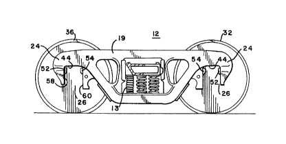
Railcar truck 10, as illu~lldte~ in Figures 1 and 6, is generally an ass~lllbly of three main
col~oll~nls, that is first side frame 12, second side frame 14 and bolster 16 ~
~cl~ eell at about l~,Sp~;liVe side-frame midpoints 15 and 17 of parallel side frames 12 and
14. Bolster 16 is about normal to each of side frames 12 and 14. Side frames 12 and 14 are
20generally parallel to lon~ihl.iin-ql truck axis 18, which axis 18 may thus be considered as the
longih~t1inql axis of side frames 12 and 14 (see Figure 1). Side frames 12 and 14 include first end
20 and second end 22, which ends 20 and 22 each have a pedestal jaw 24 and bearing o~l~ing 26.
As each of side-frame pedestal jaws 24 and bearing openings 26 are similar only one will be
desclibcd, but the desc~i~lion will be applicable to each of openin~c 26 and pedestal jaws 24 of
25side frames 12 and 14.
Tmck 10 is shown in Figure 6 with first and second axles 28 and 30, each having first and
second axle ends 31 and 33, l~,s~tively, with wheels 32, 34, 36 and 38 lll~)ullled on their
~,s~;live axle-ends 31, 33. Axles 28 and 30, which bo~ have second lon~ih~linql axes 29 about
normal to first axis 18, are mounted at and extend ~Iw~n lespe~,livc first and second side-frame
ends 20 and 22 of side frames 12 and 14. The various ancillary elernPnt~ of truck 10, such as
-6-
21~6~47
spring pack 13 in Figure lA and friction shoes (not noted), are a part of a typical truck assembly
10.
In Figure 1, a plan view of truck 10 notes the lon~ihl~linql and L~ c relationship
bclwccn side frames 12 and 14, and bolster 16. The elevation view of side frame 12 with wheels
32 and 36 in Figure lA demo~ ates the relative lon~ inql syllllllcll~/ of side frame 12 or 14.
As noted above, only one of pedestal jaws 24 is described, but the description will apply to any of
pedestal jaws 24 of side frames 12 and 14. An axle 28 and bearing assembly 46, as shown in
Figure 2 and Figure 6, is positionable in jaw openillg 26, but is not shown in Figure lA.
Typically axle end 31 or 33 with journal bearing 46 is secured against bearing adapter 48, which
is positioned against pedestaljaw roof 44 with wear liner 42 lll~ bcl~,en. Historically wear liner
42 has been utilized to ...;.~ the effects of lubbing and flexing of adapter 48 against roof 44,
which may result in wear and distortion of roof 44. However, the insertion of wear liner 42 also
adds a~ ,r col~oll~nt to the structure of axle end 31 and side frame 12, which introduces
further structural toleldllces to this axle-end assembly, and con~eq~ently more oppollul~ for
lateral axle-frame disp!~c~
In Figures 2, 3 and 5, axle end 31 of axle shaft 28 is noted in a pedestal jaw ~l,u~;lu~. In
Figure 2, axle shaft end 31 extends through pedestal jaw 24 and opcnillg 26 with wear liner 42
nested against jaw roof 44. Journal bearing or bearing outer race 46 is an annular bearing which
is slidably fit onto axle-shaft end 31.
ne~. ;u~ adapter 48 is secured against wear liner 42 bcl~n thrust lugs 52 and 54 of jaw
24, which lugs 52 and 54 extend into o~nillg 26 and are more clearly illustrated in Figures lA
and 7. Axle end 31 and journal bearing assembly 46 with outer surface 56 are ~etained in jaw 24
and o~ning 26 against arcuate surface 50. In Figure 2, the sepâlalion di~ e 'y' bclwcen outer
surface 56 of journal bearing 46 and inner wall 58 of openmg 26 is indi~dlive of the clea,~1ces
provided in the asscl"bly of an axle end 31 or 33, pedestal jaw 24 and opcnillg 26. This
s~p~alion ~ n~ 'y' is ac~lui,~d from the initial ,..z.,..r;.--l...i"g process tol~ ces for the various
parts of the as~mbly and is provided to assure adeql~ate cledlallce for assembly of these parts.
A wear plate-adapter-bearing assembly, which is similar to the SlluClu~ of Figure 2, is
shown in a lon~ inql cross-section in Figure 3 with roof 44 of pedestql jaw 24 glasyed by clips
41 of wear liner 42. In this figure, first lip 49 and second lip 51 of adapter 48 extend,
les~ively, over outer edge 57 and inner edge 59 of outer surface 56 to retain bearing assembly
21565A7
46 and axle 28 in position in jaw opellhlg 26. The structure of Figure 2 illustrates a previous
attempt to control the wear and flexing of an axle and side frame by insertion of an elqctom~ric
element 61 ~.~ wear plate 42 and upper surface 47 of adapter 48 to damp or accommodate
the vertical forces ~ ",i~led bclwccn a wheel and side frame. Similarly in Figure 5, the
S exploded view of axle end 31, journal bearing 46, bearing adapter 48 and wear liner 42 illu~ tes
the plurality of parts in many present axle and side frame assemblies. These bearing-axle
assemblies of Figure 5 clearly demo~llalc the -q-rc~lm~ tion of tolc ,.~-~es and clea,~lces that
provide gap ~ es, which add to the amplification or hl~lease in flexing b~,lwcen an axle 28 or
30 and side frames 12, 14 during operation of truck 10, which flexing can consequently lead to the
introduction of truck hlm~ing.
In Figure 4, h~.~ontal roof 44 and generally vertical jaw side walls 58 and 60 (cf.,Figure
lA) have been, lespe~ ,ly, displaced at an acute angle 'x' from the ho,~o,l~l (lon~itlJdinq-l
truck) axis 18 and vertical axis 68 to receive adapter 48, which is shown with generally normal
vertical and hol~o,lt~l sides in this Figure. Adapter 48 is provided at an angle 'x' in pedestaljaw
o~ning 26 and it is biased toward one of stop lugs 53 and 55 on outside or outboard surface 19 of
side frame 12. Pads 53 and 55 in Figure 4A are provided on oull,odld surface 19 and inboard
surface 21, l~,i.~;livcly, of side frame 12 to "~ in adapter 48 aligned and square with respect
to pedestal jaw 24.
In the above-described embo~lim~nt of Figures 4 and 4A, the present invention avoids the
earlier dcsc~ l use of a wear liner 42, Ill~.eb~ removing the m-q-n -f ;~ and assembly
tolerances associated with a wear liner. In this sll~clu~" bearing adapter 48 is more nearly an
integral part of side frame 12 as it has been mated to roof 44, although qn~-lqrly displaced from
the ,esp~;Live ho,~onlal and vertical axes 18 and 68 of side frame 12. In this confiy,,~ ioll, axle
28, and more ~ifil ~lly journal bearing 46, is securely nested against bearing adapter surface 50
and, in cooperation with tightly mated bearing adapter 48, provides a more secure mating b~lween
axle 28 and side frames 12 and 14 to inhibit lateral disph~e~ 1 of axle 28 and side frames 12
and 14, which con~ y inhibits or ...il.;...i~s truck h~ntin~.
The above-noted angular diSQl~~P~ I is most easily r~fe~ ced from side-frame
lon~hlldinql axis 18 and lon~itll(1inql second axis 29 axles 28 or 30, which axes 18 and 29 are
gen~-qlly normal and int~l~lhlg. As ill.~ led in Figure 1, the i"t~ ,lion of axes 18 and 29
defmes a generally hol~o,lt~l plane. Angular displ~ ~e~..P ~l 'z' in Figure 1, ~t~n the axle and
2156~47
side frame is the displ~em~nt of second axis 29 from the i"lel~eclion point of the axes and its
normal position to axis 18. This angular displ~~emPnt may be in either a fol~v~d or le~v~ld
direction in the hol,~o~ l plane, or ~ lively the noted angular displ~~çm~nt may be
considered as disp!~~,çm~nt of axis 18 relative to second axis 29. In either case, it is this small
5 angular displ~.~em~nt, 'z', which is r~f~ ced as lateral displ~rem.ont
The col"bh~lion of integrally mated side frame 12 and bearing adapter 48, as well as the
displ~em~nt of bearing adapter 48 at a small angular displ~cemPnt from hol~o,l~l and vertical
axes 18 and 68, provides the ~l~,dte~l improvement to the inhibition of lateral displ~re-m~nt of axle
28 relative to side frame 12 to ..~ini...i,~ truck Walyillg, which thus inhibits truck l-~ ing. This
angular offset of bearing adapter 48 from hol~o"lal axis 18 and vertical axis 68 disposes it to
~Ç. . the ~alyil~g load or forces to outer stop lug 53 or 55. It has been found that such load
r~r provides truck 10 with illlploved oyelalillg ~llZ.i~-h ;~lics against truck 1.. 1;.~.
In an al~ tive embodiment shown in Figure 7, angular disp!~ e~ .l of bearing adapter
48 in Oyenillg 26 can be ~cco..~,.,odat~d with a modified allange.l~ent of wear liner 42 and bearing
adapter 48: In this ~l~ r ll~ll, wedge-shaped wear liner 70 is secured to roof 44 and has its
tapered or wedge-shaped ~lignmPnt in the lon~it~ in~l direction of side frame 12. As illu~ ated,
all of tapered surface 72 of wedge-shaped wear liner 70 extends into o~nhlg 26 from roof 44. As
shown in Figure 4, upper surface 47 of bearing adapter 48 is flat and generally normal to adapter
front edge 76 and rear edge 78. Th~.efore, mounting of adapter 48 in op~ g 26 with wedge-
shaped wear liner 70 posilion~d against roof 44 will ~n~ rly displace adapter 48 in ope.~i~g 26.
This angular disp~r~ .l at roof 44 provides adapter 48 at an angle in o~nillg 26 and
co~ e.l1ly will place an angular load or bias against one of outside stop lugs 53 and 55. The
lon~itl~lin~l dil~lion of tapered surface 72, that is front-to-back or back-to-front, is not
dct~ ive of the illlylo~,~enl in the lateral (angular) displ--~mPnt ~lv~,.,en axle 28 and side
frame 12.
Tl~liic~ of the illlyrovc;lll~n~ of the angular displ~~em~ont the angular disp!~~~om~nt of
axle 28 has been l~luced from 1~ to less than 0.35~ of angular displ ~~ç~.~f.~l with the present
invention. As noted above in earlier lese~.,h work, decl.,asillg the angular disph~~çm~ont results in
i,npro~/~d truck hllnting, or more ~c~;ula~ly has been noted to il~clease the critical speed where
truck hllntin~ co.. -n~s.
5 4 7
- ~ While only a specific embodiment of the invention has been described and shown, it is
apparenl to those skilled in the art that various ~ltern~tives and mo~ifir~tions can be made thereto.
It is, ~ fol~" the intention in the appended claims to cover all such motlifir~tions and
~l~r~ /es as may fall within the true scope of the invention.
-10-