Note: Descriptions are shown in the official language in which they were submitted.
X156581
1
CONVEYING SYSTEM
Field of the Invention
The present invention reates to a conveying system available in an
assembly line of automobiles or the like, and more particularly to a plurality
of
transport cars without any driving means can be driven in close contact with
each other on an endless conveying path.
Background of the Invention
A conveying system in which a plurality of transport cars without any
driving means are driven on a fixed conveying path is known in the prior art,
as an example, from Unexamined Japanese Patent Application Publication No.
H 2-209309, published 20 August 1990 and resulting from Japanese
Patent Application No. HI-30495 filed 9 February 1989.
The conveying system comprises a friction feeder which is constituted
by friction feed rollers pressed against the side face of the transport car
and a
motor for driving the rollers and is disposed at an upper stream side of the
conveying path supporting the plurality of transport cars operably, and a
friction brake which is constituted by friction brake rollers pressed against
the
side face of the transport car and a motor for driving the rollers in a
retrograde direction and is disposed at a down stream side, wherein the
transport car contacted with the friction feed rollers is propelled by the
friction
i
_Z156581
2
feeder to push and move all of the transport cars positioned in front, and the
transport car pushed from behind is prevented, by the friction brake, from
moving onwards at high speed than the following transport car by the inertia.
However, in such conventional conveying system disclosed in the
above-mentioned Japanese Patent Application Publication No. H 2-209309,
the transport car is a rigid structure consisting of one carriage, so that the
following problems were encountered.
That is, the transport cars may be pushed and driven smoothly on a
straight path, whereas, for example, on a curved horizontal path, a refraction
angle between the preceding and following transport cars or an angle refracted
from the straight serial condition is large, so that a forward component force
of the preceding transport car in a push force exerted on the preceding
transport car from the following transport car becomes smaller and a running
resistance of the preceding transport car increases, thus the pushing
operation is
not performed smoothly. The longer the total length of the transport car, the
more remarkable the phenomenon, so that such transport cars were not
available in a conveying system for long objects.
Summary of the Invention
A primary object of the present invention is to provide a conveying
2156581
3
system allowing even a longer transport car to push and propell on curved
horizontal or vertical paths.
With the above and other objectives in view, the present invention
provides a conveying system which comprises guide rails disposed along a
conveying path having curve sections, transport cars supported movably by said
guide rails, and a friction feeder for the transport cars, wherein said
transport
cars comprises a main body supported onto said guide rails movably by
guidance means and a support for objects to be conveyed, while said main
body has a plurality of movable bodies in the running direction, coupling
means for coupling the movable bodies so as to allow a relative yielding
motion between the movable bodies at the curve sections in the conveying
paths, and driven faces formed on the movable bodies in parallel to the
running direction, and said support for objects to be conveyed is provided on,
at least, one of said movable bodies, wherein said feeder is disposed at a
suitable location in said conveying path and comprises a feed roller adapted
to
act on the driven faces of said movable bodies and a motor for driving the
feed roller.
According to the conveying system of the present invention, even when
the total length of the transport car becomes longer due to the long objects
supported on the support, the main body supported and guided on the guide
..V~._.~.,.r...~....~~:~.~~~~"~v__.. . _._.. ___,~...~.~ _._.
...._~.._.~..~r~._...._._.~......._.~_..,._~.__._.__.__..
2156581
4
rails via the guidance means is constituted by the movable bodies divided into
plural numbers in the running direction and coupled flexibly by the couplers,
so that a refraction angle between the movable bodies when transport on the
curved horizontal path, or the angle refracted from the straight serial
condition
is small. In other words, the refraction angle between the front movable body
of the following transport car and the rear movable body of the preceding
transport car, when passing the curved horizontal path in the state where the
preceding transport car is pushed by the following transport car, becomes
smaller.
Thus, in an arrangment in which front and rear ends of the main body
of the transport cars are provided with a contact portion adapted to contact
one
another when the preceding transport car is pushed by the following transport
car, the feed rollers act on the driven portion forwards by the feeder, when
used as pushing and propelling the preceding transport car, the push force of
the following transport car acts efficiently as a forward propelling force of
the
preceding transport car on the curved horizontal path, thus it can be pushed
and driven smoothly.
Also, since the movable bodies constituting the main body of the
transport car can be formed into a bar shape which is sufficiently smaller
than
a width of the support supporting the objects, when used as pushing and
2156581
s
propelling the preceding transport car as mentioned before, even on the curved
horizontal path, an amount of lateral variance of the acting position from the
curved horizontal guide rails can be limited to the minimum, thus it can be
pushed and driven smoothly and efficiently.
s In an embodiment of the conveying system of the present invention, in
the conveying path, there are a zone in which the transport car is pushed and
driven by said feeder, and a zone in which the transport car is forcibly
driven
by a disengageable feeder is provided, wherein said disengageable feeder
comprises a driven body disposed at a front-end portion of the main body of
the transport car, drive-release operating means disposed at a rear-end
portion
of the main body, a pusher moving along the conveying path and engaged to
said driven body, and said driven body and said pusher are disengageable with
each other so that, when the following transport car approaches to the
preceding quiescent transport car, said drive-release operating means of the
1 s preceding quiescent transport car disengages the driven body of the
following
transport car and the pusher.
According to such configuration, the transport cars can be connected one
after another in train and driven at a constant speed in the pushing and
driving
zone, and the transport cars can be suitably spaced corresponding to the
distance of the pusher and driven at a constant speed in the forcible driven
..... .. . , ,..~._.~...~._._.~... _~.W.....n~w~.~...... .... _...~..~.~ .
........._. ......~_~...~~...~... _. . .. .. ,.~.w,......~.. :_ _...~ ....:
..~_ ._._v..
2156581
6
zone by the disengageable feeder. In other words, while conveying the objects
by the same transport car, the running condition can be changed responsive to
works on the objects, and the transport cars can be stored automatically in
the
forcible driven zone by the disengageable feeder.
In this case, the driven unit is mounted on the guidance means disposed
on the front end of the front movable body, and the drive-release operating
unit is mounted on the guidance means disposed on the rear end of the rear
movable body, at least, one of the guidance means with the driven unit and the
guidance means with the drive-release operating unit being supported movably
within a fixed range in the running direction relative to the movable body
supporting the guidance means, and held at a fixed position by a spring.
In such configuration, when the transport cars are pushed and driven by
the feeder, the guidance means with the driven unit and the guidance means
with the drive-release operating unit, which are positioned respectively at
the
front end of the following transport car and at the rear end of the preceding
front transport car, are adjacent to each other. The drive-release operating
unit
of the preceding transport car is in the state of switching the driven unit of
the
following transport car to a non-operating position (disengaging position to
the
pusher). Thus, when there is a curved vertical path forming opposite ends of
an ascending path and a descending path in the traveling path, and, further
...:...,_w..~.~..~..._..~...._...~~......._-...~.-
_...._~.......,_~..w".~.~.~__.~,_._w.__. ~..._.m_~~... .. ..... . .. .u~._ ,~
... ... . _...~~_. .. .. _ __ _...a..._.. _...
21565 81
where the main body (movable bodies) is on the upper side relative to the
guide rails, the contact positions for pushing the preceding and following
transport cars separate as the transport car passes the end portion of the
ascending path and the start portion of the descending path, and the pushing
operation is carried out by the guidance means with the driven unit positioned
at the front end of the following transport car and the guidance means with
the
drive-release operating unit positioned at the rear end of the preceding
transport car.
However, according to the above-mentioned configuration, an urging
force by the spring is set weaker than a pushing force by the feeder, so that,
when the guidance means with the driven unit positioned at the front end of
the following transport car and the guidance means with the drive-release
operating unit position at the rear end of the preceding transport car push
one
another as aforementioned, at least one of the guidance means is retreated
against the urging force of the spring, and the contact portions at end
portions
of the movable body for transferring the pushing force are contacted one
another to prevent the distance between the preceding and following transport
cars from becoming larger and to accomplish a good pushing operation.
Furthermore, an engage piece and an engageable portion which are
disengageable one another and coupling the adjoining preceding and following
.... _...r ~.~w....r~__.. _.~.~..._..~....._...__ _ .._ ._.~~.. ~.~... _ ... ~
.. _~,..... .. ..w_ _~ ~.. . .....
2156581
g
transport cars can be disposed at the front and rear ends of the transport
cars.
According to this configuration, the adjoining preceding and following
transport cars are connected in train by coupling one another with the engage
piece and the engageable portion and are driven by the feeder, thereby a group
of following transport cars at the upper stream side of the feeder are also
traetive and drivable.
In an embodiment of the conveying system in which the conveying path
is endless and the transport cars arranged in closed contact throughout the
endless conveying path are circulated in a unit, the movable bodies of the
main
body of the transport car can be coupled one another swingably in the
laterally
horizontal direction by the coupling means, and the transport cars can be
connected in endless train by the coupling means for coupling one another
swingably in the laterally horizontal direction.
In the case of adopting such configuration, the main body of the
transport cars may be constituted by the movable body having the support for
objects being conveyed and the movable body having a work deck so that,
even during conveying the objects, the operator on the work deck can work on
the objects mounted on the support for objects.
Also, an expansion allowable portion is provided for allowing the
......... .......~ ..rm.w...~..... ~..~ _.. ...... .... ~ .~.. __.~_~~.._~~...
> >....ri.~4.....~ _..
2~,5658~.
expansion of total length of the group of transport cars connected in endless
train, so that the movable bodies turning along the circular curved horizontal
path in the endless conveying path makes change in position so as to prevent
an excessive tension and unreasonable slack on the group of transport cars
connected in endless train for smooth rotation thereof.
Meanwhile,at least one movable body among the movable bodies
constituting the main body of, at least, one of the transport cars is
constituted
adjustably lengthwise in the running direction, so that an error between the
total length of the endless conveying path and the total length of the group
of
transport cars connected in endless train n the conveying path can be absorbed
by adjusting the length of the movable bodies.
In the following, some preferred embodiments of the present invention
are described with reference to the accompanying drawings.
Brief Description of the Drawings
Fig.1 is a side view showing a first embodiment of the present invention
and a transport car being pushed and driven;
Fig.2 is a plan view showing the transport car;
Fig.3 is a partly cross-sectional view showing a coupling means in a
........... ...... .I ...... .............._.. ._...............W
._....._.,.......W..m...., ... _ ~",_...
.......,........_..,...,_",.......,..W-._,........ .......,_r,......,"_.....
......~._",..... ,....
2156581
to
main body of the transport car;
Fig.4 is a side view showing a contact portion between the transport
cars;
Fig.S is an expanded cross-sectional plan view of essential portion of
the contact portion.
Fig.6 is a cross-sectional front view showing a drive furnace to which
objects being conveyed is conveyed by the transport car;
Fig.7 is an expanded front view of essential portions;
Fig.8 is a plan view of a feeder driving the transport car;
Fig.9 is a partly cross-sectional side view of the feeder.
Fig.lO is a side view illustrating a disengageable feeder commonly used
in the embodiment;
Fig.l1 is an expanded side view of essential portions of Fig.lO;
Fig.l2 is a partly cutaway front view of Fig.ll;
Fig.l3 is a schematic plan view showing an entire layout of a conveying
w. . . ,.m...,._.. ...-..~_..u~w_.. .. _..~.~,..~....~......~.-..._._._. _ _
zl5sssl
11
path of the embodiment;
Fig.l4 is a plan view illustrating a running state of the transport car at
a curved horizontal path in the conveying path;
Fig. 15 is a side view illustrating a running state of the transport car at
an ascending and descending path in the conveying path.
Fig.l6 is an expanded side view showing a contact portion between the
transport cars at the ascending and descending path;
Fig.l7 is a cross-sectional side view showing a second embodiment of
the present invention and a coupling state of the transport cars;
Fig.l8 is a partly cutaway plan view showing a coupling state of the
transport cars;
Fig.l9 is a cross-sectional front view showing a feeder driving the
transport car;
Fig.20 is a cross-sectional plan view showing a feeder driving the
transport car;
Fig.21 is a cross-sectional side view showing a coupler between the
7 ..w.....~... ._ . .. ..~.. _ _. . .... _.._..~.__ _ . . _ _. .....
21565 81
12
transport cars, and a detailed structure of the transport car whose main body
can be adjusted lengthwise;
Fig.22 is a cross-sectional plan view of the transport car whose main
can be adjusted lengthwise;
Fig.23 is a side view illustrating a lift used in the second embodiment;
Fig.24 is a cross-sectional front view showing the lift and the transport
car;
Fig.25 is a schematic plan view illustrating an entire layout of a
conveying path of the present embodiment;
Fig.26 is a side view showing a third embodiment of the present
invention and a transport car;
Fig.27 is a partly cross-sectional side view illustrating a main body of
the transport car;
Fig.28 is a cross-sectional front view of the embodiment;
1$ Fig.29 is a schematic plan view illustrating an entire layout of a
conveying path of the embodiment; and
.u _~...._~.~...a_.~.,~... .. _.w.._. _ .. _ . . ~..m.~..Ww....rv. _
v.....~..~..... . .......... . . . . ~ ~..:.~ ,... _... ...~ . ....
21565 81
13
Fig.30 is a cross-sectional front view illustrating a guide means of a
transport car at a U turn portion.
Detailed Description of Preferred Embodiments
( First Embodiment )
A first embodiment of the present invention is described in the
following according to the drawings.
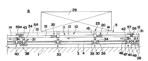
As shown in Fig. l, Fig. 2, Fig. 7 and Fig. 13, a pair of right and left
guide rails 3 facing one another in a horizontal direction at open portions
are
provided on a floor 1 via a frame 2, and a square bar-shaped guide member 4
is laid on an upper surface of upper side edge portion on the open side of the
guide rails 3. A conveying path 5 is formed by the guide rails 3, and
hereupon, as shown in Fig. 13, the conveying path 5 is formed into an elliptic
endless shape by a pair of linear sections SA which are parallel to each other
and curved horizontal sections SB connecting between start and cnd portions of
the linear sections SA.
The elliptic endless conveying path 5 is divided into two portions at a
pair of linear sections SA parallel to each other, one side of which is used
as
a dense moving zone 6 and the other side is used as an expanded moving zone
_._~_._.ry._....~ ........~ .~....._. _ .r_.. ..,. _... .... ..~.-.~__~.... .
. .......~.._.~.w_~..
21565 81
14
7. Meanwhile, in the dense moving zone 6, an ascending path Sa is
incorporated in one linear sections SA and a descending path SB is
incorporated in the other linear sections SA.
A plurality of transport cars 10 supported and guided by the guide rails
S 3 and moving on the conveying path 5 are provided. A main body 11 of the
transport car 10 is formed by three movable bodies 12, 13 and 14. The
movable bodies 12, 13 and 14 are constituted by a square cylinder and their
both side faces are formed into driven faces 15. Between the front movable
body 1 and center movable body 13, and between the center movable body 13
and the rear movable body 14 are coupled swingably with each other in
vertical and horizontal direction via coupling means 20. That is, as
shown in Fig. 1 through Fig. 3, the coupling means 20 are provided between
end members 16 integrated with the front and rear ends of the center movable
body 13 and facing ends of the front and rear movable bodies 12, 14 to
constitute a trunion type, wherein a coupler 22 is mounted to the end member
1G swingably vertically via a laterally horizontal cross pin 21, and at the
same
time, coupled swingably laterally to the facing ends of the front and rear
movable bodies 12, 14 via a vertical longitudinal pin 23.
A support for objects being conveyed 25 and a pair of front and rear
guidance means 30 in the running direction supported and guided by the guide
....~...~........~..~.~._~~.~...~.._u ...~..~.. .~~.... ... .._......ro~.. ..
..._..~.__. . .. _~__.~~.~._ _. _...._. .. ..__. ...., ._..... _..._ .... r
~I5658I
rails 3 are disposed on, at least, one of the movable bodies 12, 13 and 14,
the
center movable body 13 in this embodiment, and on the remaining movable
bodies, the front and rear movable bodies 12, 14 in this embodiment, guidance
means 31, 40 supported and guided by the guide rails 3 are disposed at free
5 ends apart from the center movable body 13 including the support for objects
being conveyed 25.
The support for objects being conveyed 25 is constituted by a bracket
27 fixed to an upper portion of the end member 1G of the center movable
body 13 via a front-to-rear horizontal joint pin 26, and laterally horizontal
10 support frames 28 provided on the bracket 27, on lateral opposite ends of
the
support frames 28, supports 28A for objects being conveyed 29 such as an
automobile body are disposed.
As pair of front and rear guidance means 30 provided on the center
movable body 13, a trolley constituted by, a vertical pin 32 fixed rotatably
to
15 the end member 16, a trolley body 34 coupled rotatably to the lower end of
the vertical pin 32 via a laterally horizontal pin 33, a pair of front and
rear
supporting horizontal shaft rollers 35 pivoted on opposite sides of the
trolley
body 34 and engaged to the guide rails 3, and a pair of front and rear steady
rest vertical shaft rollers 36 pivoted on the upper portion of the trolley
body
34 and guided between the guide members 4 of the guide rails 3 is utilized.
_.... . H _ ~ .....#,~ .. ..,.w...~ ....._ . ... ..-.~..-,...,~._... . . , . _
. ~ . . ....... _._ ..y__ . . _.... , :.. ~ _ _. _ a . .. ._.
2156581
16
The guidance means 31 provided at the free end side of the movable
body 12 also has a same configuration as the guidance means 30, and as
shown in Fig. 1, Fig. 2 and Fig. 4, utilizes a trolley constituted by, the
vertical
pin 32 fixed rotatably to an end member 17 of the movable body 12, the
laterally horizontal pin 33, the trolley body 34, the supporting horizontal
shaft
rollers 35 and the steady rest vertical shaft rollers 3G. Under the trolley
body
34, a driven unit 38 is pivoted swingably vertically at the position near its
front end by a laterally horizontal support pin 37. An engage face 38A facing
backward is formed at a portion extending backward from the support pin 37
of the driven unit 38, and an operable face 38B is formed on the upper side of
a portion extending forward from the support pin 37.
Guidance means 40 provided on the free end side of the rear movable
body 14 is coupled variably to the rear movable body 14. That is, as shown
in Fig. 1, Fig. 2, Fig. 4 and Fig. 5, a fate-shaped bracket 41 is disposed
under
the end member 18 provided on the free end side of the rear movable body 14,
and a laterally horizontal pin 42 is disposed on the bracket 41. A
front-to-rear movable body 43 is fixed movably in a front-to-rear direction to
the laterally horizontal pin 42.
A longitudinal pin 45 is disposed downward in a body from the
front-to-rear movable body 43, and a trolley body 4G of the guidance means
.. ~,__........_ . ~....v.....a... ~~,~..u .... . ~~,~~.~~,. _.._.._ ... ~
.......~... r _.A~.~._ .:_. . ... _.. . _._._.~..~.
21565 81
1~
40 is mounted rotatably to the longitudinal pin 45 as same as aforementioned.
Supporting horizontal shaft rollers 47 and a steady rest roller 48 are pivoted
on
the trolley body 46. Thereby, the guidance means 40 is coupled to the rear
movable body 14 rotatably about an axis 42A of the laterally horizontal pin
42, and further, coupled movably within a fixed range in a front-to-rear
direction via the pin 42 and the front-to-rear long hole 44. Under the trolley
body 4G, a drive-release operating unit 49 of the following transport car,
which acts on the operable face 38B of the driven unit 38 to swing the driven
unit 38 as such that the engage face 38A moves upward, is protruded
backward. The guidance means 40 is provided with a spring 50 which
urges and moves it backward. That is, a pair of right and left side plates 51
of a gate-shaped bracket 52 are supported by opposite ends of the laterally
horizontal pin 42, and the spring 50 is interposed between a cradle 54 mounted
backward to the bracket 52 via a front-to-rear position adjusting bolt 53 and
a
cradle 55 facing forward and formed in a body with the front-to-rear movable
body 42.
The front and rear ends of the main body 11 of the transport car 10, or
the front end of the end member 17 of the front movable body 12 and the rear
end of the end member 18 of the rear movable body 14 are formed into
contact portions SG, 57. On the upper front end side of the front movable
body 12, a hooked engage piece 59a extending forward is pivoted swingably
... . ._ .. r ~_ ~..... ~._.. _~........... ~.. .. ~.-.m...~..~~~ . _~,~.._.
.. _..._._. ... .. . .._ . .... _._..
2156581
18
vertically by a laterally horizontal cross pin 58, and a protruded engageable
portion 59b is provided on the upper rear end side of the rear movable body
14. By engaging the engage piece 59a to the engageable portion 59b of the
transport car 10 in the immediate front, the transport cars 10 can be coupled
in
train. The engage piece 59a is held at a fallen engage state by gravity or a
spring.
As shown in Fig. 6, Fig. 7 and Fig. 13, in the dense moving zone G, a
dry furnace 60 is provided from a slightly upper stream side of the ascending
path 5a to a slightly downstream side of the descending path 5b. The dry
furnace 60 is constituted by a rectangular cylindrical wall body 61 and dryers
62 arranged inside the wall body 61, the linear path 5A and the curved
horizontal path 5B are disposed.
In the dense moving zone 6, at a slightly upper stream side from an
inlet of the dry furnace 60, a friction feeder 70 which acts on the driven
faces
15 on both side faces of the main body 11 of the transport car 10 to give
propelling force to the transport car 10 is provided. The friction feeder 70
includes the movable bodies 12 to 14.
That is, as shown in Fig. 8 and Fig. 9, on the lateral side of the guide
rails 3, a longitudinal shaft 72 is disposed on a base body 71 extending from
the frame 2, and a support member 74 is mounted to the longitudinal shaft 72
.... ,,.._..._~Y_ ~~_...m..~._..~.. ... _. .v_~.~_.._.r_ . _. .. _ . .....__ _
. ___., .a_._ _ . . .. . . __. _. ... . .. ...
21565 81
19
swingably about a longitudinal axis 75 via bearings 73. A motor 76 and a
reduction gear 77 are disposed on the support member 74, a friction feed
roller
79 made of, for example, urethane is mounted to an output shaft 78 of the
reduction gear 77, and the friction feed roller 79 is driven by the motor 76
via
the reduction gear 77. An arm 80 is connected to the support member 74 and
a cylinder unit 81 is interposed between the arm 80 and the base body 71.
Thus, by operating the cylinder unit 81, the support member 74 is
swung bout the longitudinal axis 75 to move the friction feed roller 79 to and
from the driven face 15 on one side of the main body 11 of the transport car
10. For the purpose of deciding a marginal approach of the friction feed
roller 79 against the driven face 15 at that time, a contact member 82 is
disposed on the support member 74 and a stopper 83 contacting with the
contact member 82 is provided adjustably on the base body 71. Facing the
friction feed roller 79, a counter roller 84 contacting to the other driven
face
15 is disposed rotatably, only freely, via the longitudinal axis 85.
As shown in Fig. 13, in the dense moving zone 6, at a slightly
downstream side from an outlet of the dry furnace 60, a friction brake 90
which acts on the driven face 15 of the main body 11 of the transport car 10
to give braking force to the transport car 10 is provided. Furthermore, at a
slightly upper stream side of the friction feeder 70, feed-in means 95 is
.... _. _. ~. mww ..w.~. ~..~ .._. . .~_ _ ..m.... . ....w.. ~
~....~.~..~.~..,d~... . . _ ..
2156581
disposed, and at slightly downstream side of the friction brake 90, feed-out
means 9G is disposed. Arrangement patterns of the means 70, 90, 95 and 96
are changed variously, and the friction brake 90, feed-in means 95 and
feed-out means 95 may be omitted partly or entirely.
5 The friction brake 90 is constructed as same as the friction feeder 70,
and is constituted by, a friction brake roller 91 which is made of, for
example,
urethane and contacts to and separates from the driven face 15 on one side of
the main body 11 of the transport car 10, to torque motor 92 which gives a
reverse rotating force B to the friction brake roller 91 and a counter roller
93
10 to which the other driven face 15 is contacted. The reverse rotating force
B
given by the torque motor 92 is set smaller than a feed rotating force A of
the
motor 7G of the friction feeder 70. The feed-in means 95 and the feed-out
means 9G are also constructed as same as the friction feeder 70.
In Fig. 10 through Fig. 13, in a path from the vicinity of the starting
15 end to an exit of the curved horizontal path SB in the expanded moving zone
7, a disengageable feeder 100 having a pusher 107 which is engageable to and
disengageable from the driven unit 38 of the transport car 10 is provided.
That is, under the guide rails 3, a pair of right and left channel guide rails
101
are supported by the frame 2 as facing their open portions one another.
20 The pusher 107 is constituted upward in a body from one of side links
.... . _ _. ~M~...~_..._W._.._ __.m.... .._.__r_ . _. _..
.__..~....~.,.._..... ~ _...... . ..~ .. . .... .W r~__._... ...
_ 21565 81
21
103 constituting a drive chain 102, and on front and rear center links 103 of
the side link with pusher 103, a trolley 105 provided with a pair of right and
left supporting horizontal shaft rollers 106 engaging to the guide rails 101
is
mounted. The drive chain 102 is stretched endlessly between a plurality of
guide gears 108 and a drive gear 110 coupled to and interlocking with a motor
unit 109.
In a path from the exit of the curved path 5B to the vicinity of end
portion in the expanded moving zone 7, a high-speed feeder 115 which drives
the transport cars 10 at high speed is disposed. As the high-speed feeder 115,
for example, a reciprocating self-propelled tram-car type may be adopted.
On the upper stream side of the feed-in means 95 in the dense moving
zone 6, carry-in means 116 from the preceding process and transfer means 117
for transferring the objects being conveyed 29 between the carry-in means 116
and the transport car 10 are disposed. At an inlet of the curved path 5B in
the expanded moving zone 7, carry-out means 118 to the following process
and transfer means 119 for transferring the objects being conveyed 29 between
the carry-means 118 and the transport car 10 are disposed.
Next, an example of conveying method by the transport car 10 in the
above-mentioned embodiment is described.
... _.~._._.~~......_...~~.~-...n.-.~.-.._....~..~....~.~...~....~.-.w..__..
._ ._._.._._......~..~.w.... ... ._ ._. _ _ ._.......
215fi5 81
22
In Fig. 13, the transport car 10 is stopped in such a manner that its
front end corresponds to the position of the feed-in means 95, and the objects
being conveyed 29 which is, for example, painted in the preceding process and
carried in by the carry-in means 116 is transferred to the support for objects
being conveyed 25 of the transport car 10 by the transfer means 117.
By operating the feed-in means 95 as same as the friction feeder 70 in
this state, the transport car 10 loaded with the objects being conveyed 29 is
fed out toward the friction feeder 70. At this time, the front contact end 56
of
the transport car 10 fed by the feed-in means 95 contacts to the rear contact
end 57 of the rearmost transport car 10 of the group of transport cars 10
connected in train in a row on the conveyor path 5, thereby the group of
transport cars 10 are moved forward by feed-in force of the feed-in means 95.
The feed-in means 95 stops to feed when the front end of the corresponding
transport car 10 enters the friction feeder 70. At this time, the cylinder
unit
81 in the friction feeder 70 is extended, thereby the support member 74 is
swung outward about the longitudinal axis 75 to disconnect the friction feed
roller 79 from a moving locus of the driven face 15 of the transport car 10 as
shown by a virtual line of Fig. 8. Thus, the transport car 10 is fed in
without
any hindrances.
Thereafter, the cylinder unit 81 is contracted to move and press the
.. _..a....,.~.._.~n..,w~_.y.~......~...~a....-_...a._u._.w.. __.~.-
.......c__._._.._. _ _. _~.,_ .. .u......~_._ u... _w_~ u..
2I5658I
23
friction feed rollers 79 against the driven face 15 on one side of the
transport
car 10 as shown by a solid line of Fig. 8, and at the same time, the other
driven face 15 is contacted to the counter roller 84 so as to clamp the front
movable body 12 by the rollers 79 and 84, but at this time, the friction feed
rollers 79 is rotated in the feed direction by the motor 7G. Thus, the
transport
car 10 is driven forward by feed rotating force A of the friction feed rollers
79
to push and move the group of transport cars 10 which are connected in train
in a row on the conveying path 5 in the dense moving zone G.
At this time, the guidance means 30, 31 and 40 of the transport cars 10
engaged to the guide rails 3 are that, the moving level and moving direction
are restricted by the supporting horizontal shaft rollers 35, 47 and steady-
rest
vertical shaft rollers 3G, 48, thus the transport cars 10 can be driven
smoothly
as maintaining a prescribed attitude.
A feed amount of the transport car 10 by the friction feeder 70 is
detected by an encoder and the like, and when a preset feed amount is
achieved, the friction feed rollers 79 is disconnected from the driven face 15
of the transport car 10 by the cylinder unit 81 to stop automatically.
Meanwhile, the transport car 10 moving on the conveying path 5 is braked by
the friction brake 90. That is, while the propelling operation of the
transport
car 10 by the friction feeder 70 is stopped, though the cylinder unit in the
m...~.~._..__~. .~,~..._.~. ......_ .... ~...v....~~"~~...~w.... _. .~.._...
zi~s5s1
24
friction brake 90 is contracted and the friction brake roller 91 is
disconnected
from the driven face 15 of the transport car 10, when the friction feeder 70
starts the propelling operation, the friction brake roller 91 is moved toward
the
driven face 15 by the cylinder unit and is pressed against the driven face 15
of
the transport car 10 being pushed and driven.
At this time, ,since the friction brake roller 91 is rotated in the reverse
feed direction by the torque motor 92, though the backward propelling force is
exerted on the transport car 10 by the reverse rotating force B, as the feed
rotating force A is larger than the reverse rotating force B, the friction
brake
roller 91 is rotated in the feed direction corresponding to a difference
therebetween, and the load at that time is absorbed by the torque motor 92.
By the above-mentioned operation, the transport car 10 corresponding to
the friction brake 90 is pushed and driven in the braking state, so that
between
the friction feeder 70 and the friction brake 90, a plurality of transport
cars 10
are aligned in close contact without producing any gaps therebetween. The
braking operation by the friction brake 90 is stopped automatically in
connection with stop of the propelling operation by the friction feeder 70.
Then, the transport car 10 pushed and driven from the friction brake 90
reaches the feed-out means 9G.
The transport car 10 is intermittently moved at a prescribed speed in the
2i5658i
Zs
dense moving zone 6 in such a manner, and passes through the dry furnace 60
as shown in Fig. 6 while moving intermittently, thereby the painted objects
being conveyed 29 is dried. Hereupon, since the objects being conveyed 29 is
conveyed through the dry furnace 60 by the friction feeder 70, the guide rails
s 3 may be laid close to the floor to lower a height including the transport
car
and to minimize a space inside the dry furnace 60.
The propelling operation of the transport car 10 by the friction feeder
70 is performed by acting, in order, the friction feed rollers 79 from the
driven
face 15 of the front movable body 12 to the driven face 15 of the center
10 movable body 13 and to the driven face 15 of the rear movable body 14.
As shown in Fig. 2, in the linear path 5A, since the main body 11 of
the transport cars 10, or the movable bodies 12, 13 and 14 are in a bar-shaped
attitude when viewing from above and side, the front contact end 56 contacts
to the rear contact end 57 from right behind, thus it can be pushed and driven
is smoothly and reliably.
Also, in the curved horizontal path SB, as shown in Fig. 14, when
viewing from above, the movable bodies 12, 13 and 14 are pushed and driven
in the attitude bending along the curve at the coupling means 20. THus, when
viewing from above, a relative angle &Hl between the rear movable body 14
of the preceding transport car 10 and the front movable body 12 of the
2156581
26
following transport car 10 is obtuse, and the front contact end 56 contacts to
the rear contact end 57 at an obtuse angle for push and drive. At the coupling
means 20, bending between the movable bodies 12, 13 and 14 is performed by
swinging about the longitudinal pin 23. Meanwhile, since the guidance means
30, 31 are horizontally swingable about the vertical pin 32, and the guidance
means 40 is horizontally swingable about the longitudinal pin 45, they are
directed automatically along the horizontal curve of the guide rails 3.
Also in the case of running on the ascending path 5a and descending
path 5b, as shown in Fig. 15, when viewing from the side, a relative angle B2
between the rear movable body 14 of the preceding transport car 10 and the
front movable body 12 of the following transport car 10 is obtuse, and front
contact end 56 contacts to the rear contact end 57 at an obtuse angle for push
and drive. At this time, at the coupling means 20, bending between the
movable bodies 12, 13 and 14 is performed by swinging about the cross pin
21. Meanwhile, since the guidance means 30, 31 are vertically swingable
about the laterally horizontal pin 33, and the guidance means 40 is swingable
vertically about the axis 42A of the laterally horizontal pin 42, they are
directed automatically along the the vertical curve of the guide rails 3.
At the end portion of the ascending path 5a and the start end of the
descending path 5b, by the aforementioned relative angle B2, the trolley body
21565 81
27
34 of the guidance means 31 in the front movable body 12 of the following
transport car 10 contacts to the trolley body 4G of the guidance means 40 in
the rear movable body 14 of the preceding transport car 10, and the front
contact end 56 does not contact to the rear contact end 57.
However, as shown in Fig. 16, by biasing force between the trolley
bodies 46, 34 at this time, the front-to-rear movable body 43 swings about the
laterally horizontal pin 42 (the laterally horizontal axis 42A) relative to
the
bracket 41 and moves forward against urging force of the spring 50, as a
result, the guidance means 40 of the rear movable body 14 moves forward
relatively, thereby, though the trolley bodies 46, 34 are contacted one
another,
an actual push force is transmitted reliably from the following transport car
10
to the preceding transport car 10 by the mutual contact between the contacts
57 and 56.
When the rear movable body 14 of the preceding transport car 10 and
the front movable body 12 of the following transport car 10 become horizontal
after moving into the horizontal path, the front-to-rear movable body 43
returns backward by the urging force of the spring 50. The front-to-rear
movable body 43 moves within a front-to-rear free moving range of the
laterally horizontal pin 40 in the front-to-rear long hole 44.
The transport car 10 reaching the feed-out means 96 as
2156581
28
above-mentioned is fed to the expanded moving zone 7 by the feed-out means
96. In the expanded moving zone 7, as shown in Fig. 10 through Fig. 13, the
drive chain 102 of the disengageable feeder 100 is driven by the motor unit
109, and the pushers 107 provided at a prescribed pitch are engaged to the
driven unit 38 of the transport car 10 fed into the expanded moving zone 7.
Thereby, the transport cars 10 are expanded at a prescribed pitch and moved at
a constant speed in the expanded moving zone 7 by the pushers 107.
When the preceding transport car 10 is stopped by a stopper disposed at
any location in the expanded moving zone 7, the operable face 38B of the
driven unit 38 of the following transport car 10 runs over the drive-release
operating unit 49 of the preceding transport car 10 to cause the driven unit
38
to swing in such a manner that the rear end side rises to disengage the engage
face 38A of the driven unit 38 from the pusher 107. Thereby, on the upper
stream side from the stopper, the following transport cars 10 can be stopped
in
order for storage.
By stopping the transport car 10 at the carry-out means 118, the objects
being conveyed 29 on the transport car 10 can be transferred to the carry-out
means 118 by the transfer means 119. The empty transport car 10 is again
driven to the exist of the curved horizontal path 5B by the disengageable
feeder 100. Then, the high-speed feeder 115 is acted on the transport car 10
2156581
29
and the empty transport car 10 is fed at high-speed to the dense moving zone
6 and stopped after reaching the feed-in means 95.
In the expanded moving zone 7, by engaging the front engage piece 59a
of the following transport car 10 to the rear engageable portion 59b of the
preceding transport car 10, the group of transport cars 10 can be connected in
train, and by acting the disengageable feeder 100 and high-speed feeder 115
on the front transport car 10 in such a state, the group of transport cars 10
can
be driven by traction. It is to be understood that, also in the conveying path
where the transport car 10 is pushed and driven by the friction feeder 70, by
connecting the transport cars 10 in train by the engage piece 59a and
engageable portion 59b as aforementioned, the group of transport cars 10 on
the upper stream side of the friction feeder 70 can be driven by traction, and
the group of transport cars 10 on the downstream side of the friction feeder
70
can be pushed and driven.
Though the guidance means 40 of the rear movable body 14 is in the
above-mentioned embodiment, the guidance means 31 of the front movable
body 12 may be coupled variably to the front movable body 12, or the
guidance means 31, 40 may be coupled variably to the movable bodies 12, 14.
Also, in the above-mentioned embodiment, though the driven unit 38 is
2156581
constituted disengageably with the pusher 107, which may be constituted
disengageably with the driven unit 38.
Furthermore, in the above-mentioned embodiment, though the main body
11 of the transport car 10 is constituted by three bar-shaped movable bodies
5 12, 13 and 14, the number of movable bodies constituting the main body 11
may be any numbers above two. In this case, the position of the movable
body including the support for objects being conveyed 25 may be at the front,
rear or any intermediate position of the main body 11.
The coupling means 20 is not restricted to those provided with the cross
10 pin 21 on the center movable body 13 and the longitudinal pin 23 on the
front
and rear movable bodies 12, 14 as the above-mentioned embodiment. For
example, the center movable body 13 may be provided with the longitudinal
pin and the front and rear movable bodies 12, 14 may be provided with the
cross pin, or they may be connected rotatably by means of ball joints.
15 The friction feeder 70, feed-in means 95, feed-out means 9C and
friction brake 90 in the above-mentioned embodiment are that, though the
friction feed rollers 79 and the friction brake rollers 91 are forced-drive
rollers
and the counter rollers 84, 93 are free-drive rollers, the latter may also by
the
forced-drive rollers. Furthermore, the counter rollers 84, 93 may also be
20 constituted disengageably with the driven face 15 of the transport car 10.
2156581
31
Also, in this above-mentioned embodiment, though the guide rails 3,
101 are laid on the floor, they may be laid in a pit under the floor to lower
the total height above the floor including the transport car 10.
( Second Embodiment )
Next, a second embodiment of the present invention is described
according to Fig. 17 through Fig. 25.
As shown in Fig. 17 through Fig. 19 and Fig. 25, a frame 202 is
disposed on a floor in a pit 208 formed under a floor 201, a pair of right and
left channel supporting guide rails 203 are laid via the frame 202 as facing
their open portions outward, and between the supporting guide rails 203,
steady-rest guide rails 204 consisting of the same channel steel are laid via
the
frame 202. By the guide rails 203, 204, an endless conveying path 205
consisting of, a pair of linear paths 205a which are parallel to each other
and
curved horizontal paths 205b connecting between start and end portions of the
linear paths 205a, is formed.
Numeral 200 designates a transport car supported and guided by the
supporting guide rails 203 for movement on the conveying path 205, and as
shown in Fig. 17 and Fig. 18, constituted by a main body 210, a support for
objects being conveyed 253 and a work deck 250. The main body 210 is
21565 81
32
constituted by two bar-shaped movable bodies 215, 241 coupled by coupling
means 240A. The transport cars 200 are connected in endless train by
coupling means 240B.
The support for objects being conveyed 253 is disposed on a frame 211
supported on the front movable body 215 of the main body 210, and the work
deck 250 is supported on the rear movable body 241 of the main body 210.
The frame 211 has a rectangular shape formed by a pair of right and
left front-to-rear members 212 and a pair of front and rear right-to-left
members 213, and at front and rear ends of the front-t-rear members 212, free
wheels 214 rolling on the supporting guide rails 203 are disposed. As shown
in Fig. 21, above the frame 211, support supporting means 225 for positioning
and supporting the support for objects being conveyed 253 from above is
disposed. The support means 225 is fixed inside a center portion of the pair
of right and left front-to-rear members 212 of the frame 211, and constituted
by a pair of right and left blocks 225 including a vertical positioning hole
227
and receive members 228 fixed at plural locations on the pair of right and
left
front-to-rear members 212. As shown in Fig. 19, the frame 211 is so set that
its upper surface is slightly below the floor surface 201a.
As shown in Fig. 17 through Fig. 19 and Fig. 21, the support for
objects being conveyed 253 supported on the frame 211 is formed into a flat
2156581
33
frame by a window frame-shaped outer frame 254, front-to-rear frames 255
right-to-left frames 256 disposed inside the outer frame 254, thereunder, a
pair
of right and left positioning pins 257 engageable to the positioning holes 227
of the support supporting means 225 from above are provided downward, and
space plates 258 supported by the receive members 228 are provided. A flat
plate 259 is disposed on the frames 254 to 256 as required.
The front movable body 215 is disposed under the frame 211 at its
lateral center in parallel to the running direction, and is constituted by a
main
body 217 consisting of a square cylinder and connecting 218 formed on front
and rear ends of the main body 217, right and left side faces thereof being
formed into flat driven faces 219. Under the connections 218, steady-rest
vertical shaft rollers 223 clamping the steady-rest guide rails 204
respectively
from both sides at the front and rear portions are mounted via brackets 222.
The rear movable body 241 supporting the work deck 250 is formed by
a square cylindrical main body 243 and connections 244 disposed on front and
rear ends of the main body 243, right and left side faces thereof being formed
into flat driven faces 247. The work deck 250 is fixed to the upper side of
the connection 244 at opposite ends of the rear movable body via a mounting
plate 251 (refer to Fig. 21). The work deck 250 has a substantially same
width as that of the support for object for objects being conveyed 253, and on
2156581
34
one side positioned outside from the supporting guide rails 203 when running
on the curved horizontal path 205b shown in Fig. 25, as shown in Fig. 18, a
triangular protrusion deck 250a protruding toward front and rear sides is
formed in a body. The protrusion deck 250a is disposed to position above the
frame 21.1 under the support for objects being conveyed 253.
The coupling means 240A coupling the front movable body 215 and the
rear movable body 241 is constituted by the adjoining connections 218, 244 of
the movable bodies 215, 241, and a vertical longitudinal pin 242A connecting
the connections 218, 244 swingably in the laterally horizontal direction.
The coupling means 240B coupling the transport cars 200 one another is
constituted by the rear connection 244 of the rear movable body 241 in the
front transport car 200, front connection 218 of the front movable body 215 in
the rear transport car 200 and a vertical longitudinal pin 242B coupling the
connections 218, 244 swingably in the laterally horizontal direction.
Though the many transport cars 200 constituted as mentioned above, the
main body 210 of, at least, one of the transport car 200A among the transport
cars 200 is constituted as such that a length in the running direction can be
adjusted.
That is, as shown in Fig. 17, Fig. 18, Fig. 21 and Fig. 22, the front
2156581
movable body 215 supporting the frame 211 in the main body 210 of the
transport car 200A is divided into front and rear movable bodies 215a, 215b,
which are respectively provided with concentric screw holes 230 in the
front-to-rear direction on divided end faces thereof, and coupled adjustably
5 lengthwise in the running direction by a screw shaft 231 whose inverse screw
portions at opposite ends engage to the screw holes 231 and two lock nuts
234. On opposite sides of the movable bodies 215a, 215b, front-to-rear
depressions 232 arc formed, and between the front and rear depressions 232, a
joint plate 233 for continuing the driven faces 219 is engaged and fixed. The
10 joint plate 233 is fixed to one movable body 215b by means of a bis or the
like, and mounted to the other movable body 215a via a bis and a
front-to-rear long hole.
Since the length of the frame 211 supported by the movable body 215
whose length is adjustable is fixed, mounting plates 216 secured to the
15 connections 218 at opposite ends of the movable body 215, and mounting
plates 213a secured to the frame 211 as overlapping thereon are connected by
long holes 213b provided in the mounting plates 213a in the running direction
and bolts 213c extending through the long holes 213b and engaging to the
mounting plates 21G.
20 At least one of the coupling means 240B coupling the transport cars
z~5s5s~
36
200, 200A to form an endless train and the coupling means 240A coupling the
front and rear movable bodies 215, 241 of the transport cars 200, 200A, in
this
embodiment, as shown in Fig. 17, Fig. 21 and Fig. 22, the coupling means
240B between the transport car 200A whose length of the main body 210 is
constituted adjustably and the rear transport car 200 is constituted movably
within a fixed range in the running direction.
That is, the connections 218 at opposite ends of the front movable body
215 supporting the support for objects being conveyed 253 (frame 211) of the
transport cars 200, 200A include vertical pin holes 221 through which the
longitudinal pins 242A, 242B are inserted, and at the same time, depressions
220 are formed between the mounting plates 216 secured on the connections
218, and further, the connections 244 at opposite ends of the rear movable
body 241 supporting the work deck 250 of the transport cars 200, 2UOA are
formed so as to be inserted into the depressions 220, and vertical pin holes
245, 248 communicating with the pin holes 221 are formed.
Now, though the longitudinal pins 242A, 242B inserted downward
through the mounting plates 216 and supported by the mounting plates 21G at
its head portions are to be inserted into the pin holes 221, 245 or pin holes
221, 248, at the coupling means 240B between the transport car 200A whose
length of the main body 210 is adjustable and the front transport car 200, the
2156581
37
pin hole 248 provided at the connection 244 is formed into a front-to-rear
long hole as shown in Fig. 21.
As shown in Fig. 25, at a prescribed location in the conveying path 205,
or at a location near the end portion of one linear path 205a, a friction
feeder
260 which acts on the right and left driven faces 219, 247 of the main body
210 (front and rear movable bodies 215, 241) of the transport cars 200, 200A
is disposed. As shown in Fig. 17, Fig. 19 and Fig. 20, the friction feeder 260
includes a friction feed roller 268, a motor 265 for driving the same and a
cylinder unit 270 which moves the friction feed roller 268 to and from the
driven faces 219, 247.
Particularly described, a longitudinal shaft 262 is erected on a base body
261 provided on the floor 201 on the lateral side of the supporting guide
rails
203, and a support member 263 is supported by the longitudinal shaft 262
swingably about the longitudinal axis via a bearing 264. The motor 265 and a
reduction gear 266 connected thereto in an interlocking fashion are mounted to
the support member 263, and the friction feed roller 268 made of, for example,
urethane is fixed to an output shaft 267 protruding upward from the reduction
gear 266. An arm 269 extending outward is disposed in a body on the support
member 263, and between the arm 269 and the base body 261, the cylinder
unit 270 is interposed for swinging the support member 263. Rollers 271
_ z~5s5s~
38
supporting the support member 263 and an anti-floating roller 272 are pivoted
on the base body 261.
Thus, by operating the cylinder unit 270, the support member 263 is
swung about the longitudinal axis to move the friction feed roller 268 to and
from the driven faces 219, 247 on one side. For the purpose of restricting the
maximum and minimum approach of the friction feed roller 268 against the
driven faces 219, 247 at this time, a limit-type detector 273 is provided.
Facing the friction feed roller 268, a counter roller 274 for receiving the
other
driven faces 219, 247 is pivoted freely by a longitudinal shaft 275. As
shown in Fig. 25, at a plurality of locations on the linear path 205a provided
with the friction feeder 260, work stations 279 are provided and lifts 280 for
lifting the support for objects being conveyed 253 from the transport cars
200,
200A are disposed on the work stations 279.
That is, as shown in Fig. 23 and Fig. 24, a flat frame 281 is disposed
on the floor 201, and guide members 282 positioned outside the supporting
guide rails 203 arc erected from the four corners of the frame 281. Lift
members 284 guided via rollers 283 arc disposed on the guide members 282,
and between upper ends of a pair of lift members 284 in the running direction
among the lift members 284, lift girders 285 are disposed. Contact members
286 contacting freely to the support for objects being conveyed 253 from
zl5s~ sl
39
below are provided on the lift girders 285. For moving the lift girders 285 up
and down, between the lower portion of the frame 281, pantograph mechanisms
287 are disposed and a cylinder unit 288 for operating the pantograph
mechanisms 287 in synchronism is provided.
As shown in Fig. 25, in the conveying path 205, at an outlet of the
curved horizontal path 205b after passing the friction feeder 260, a conveying
path of a ceiling suspension conveyor 290 is disposed for intersection at two
locations, the intersection near the curved horizontal path 205b being formed
into a unloading portion 291 and the intersection apart from the curved
horizontal path 205b being formed into a loading portion 292. As the
suspension conveyor 290, those having a hanger provided on a self-driven
truck and those having the hanger provided on a chain-driven trolley are
adopted. At this time, it can be constituted as such that, an engage member
on the hanger side is engaged to the support for objects being conveyed 253 to
position the hanger.
Next, the operation of the second embodiment is described.
In the case of installing a conveying system using the transport cars
200, 200A, when the longitudinal pin 242B deviates in a front-to-rear
direction from an approximate center of the long pin hole 248 in the coupling
means 240B between the transport car 200A and the following transport car
215x5 si
200 shown in Fig. 20, due to an error in the total length of an endless train
consisting of a plurality of transport cars 200, 200A, the length in the
running
direction of the main body 210 (front movable body 215) of the transport car
200A is adjusted to absorb the error.
5 That is, one side of the joint member 233 shown in Fig. 21 is removed
and the screw shaft 231 is turned while loosening the bis fixing the other
joint
member 233 and the movable body 215x, thereby the front and rear movable
bodies 215a, 215b arc moved to and from each other in the running direction
to adjust the total length of the movable body 210 (front movable body 215),
10 and to adjust the longitudinal pin 242B at the coupling means 240B to
position
at an approximate center of the long pin hole 248. The screw shaft 231 is
fixed by the lock nuts 234 after adjustment. Before adjusting the length of
the
front movable body 215, the bolts 213c connecting the mounting plate 216 on
the side of movable bodies 215a, 215b and the mounting plate 213a on the
15 side of frame 211 are loosened, and tightened after adjustment. At this
time,
the running direction of the front movable body 215 and the running direction
of the support for objects being conveyed 253 are approximately centered.
The endless train consisting of a number of transport cars 200, 200A
assembled and installed as mentioned above is operated as follows. That is,
20 while the transport cars 200, 200A are standing still, the cylinder unit
270 in
2156581
41
the friction feeder 260 is extended to swing the support member 263 outward
about the longitudinal axis, thereby the friction feed roller 268 is separated
from the driven faces 219, 247 as shown by a virtual line of Fig. 20.
When the endless train (transport cars 200, 200A) is driven, the cylinder
unit 2.70 is contracted to move the friction feed roller 268 driven in the
feeding direction by the motor 265 toward the moving path of the main body
210 (movable bodies 215, 241) of the transport cars 200, 200A so as to be
pressed against one driven faces 219, 247, and to contact the other driven
faces
219, 247 to the counter roller 274 as shown by solid lines in Fig. 20, thereby
the movable bodies 215, 241 are clamped by the rollers 268, 274 to apply
rotational propelling force in a prescribed direction to the endless train to
drive
the endless train or the transport cars 200, 200A connected in endless train
at
a prescribed speed on the conveying path 205.
In the state of driving the endless train (transport cars 200, 200A
connected in endless train), the transport cars 200, 200A from the friction
feeder 260 on the running direction side to the expansion coupling means 240B
having the long pin hole 248 are pushed and driven via the longitudinal pins
242A, 242B of the coupling means 240A, 240B, and the transport cars 200,
200A from the expansion coupling means 240B having the long pin hole 248
to the friction feeder 260 are driven by traction via the longitudinal pins
242A,
2156581
42
242B of the coupling means 240A, 240B.
Now, since the endless train rotating the conveying path 205 is
consisting of the front and rear movable bodies 215, 241 of the transport cars
200, 200A connected in chain by the longitudinal pins 242A, 242B of the
coupling means 240A, 240B, against the conveying path 205 having the two
semicircular curved horizontal paths 205b, by the change of number and
position of the longitudinal pins 242A, 242B rotating the two curved
horizontal
paths 205b of the conveying path 205, the length of the endless train (a sum
of distance between the longitudinal pins 242A, 242B9 rotating the curved
horizontal paths 205b at opposite end portions fluctuates.
However, in the endless train (transport cars 200, 200A connected in
endless train) of the above-mentioned embodiment, since an expansion
allowing portion in the running direction is constituted by the expansion
coupling means 240B having the long pin hole 248, by the front-to-rear
relative movement of the longitudinal pin 242B in the long pin hole 248 in the
coupling means 240B, the fluctuation of length of the endless train (a Burn of
distance between the longitudinal pins 242A, 242B) rotating the curved
horizontal paths 205b is absorbed. Thus, an excessive tension is never exerted
on the transport cars 200, 200A connected in endless train or an unreasonable
slack never occurs.
215fi5~1
43
The transport cars 200, 200A moving on the conveying path 205 are
supported and guided on the supporting guide rails 203 via the swivel wheels
214, and by the steady-rest vertical shaft rollers 223 guided on the steady-
rest
guide rails 204, the transport cars 200, 200A are driven smoothly as being
directed parallel to the conveying path 205.
A feed amount of the transport cars 200, 200A by the friction feeder
260 is detected by an encoder, and when reaching the set feed amount, the
friction feed roller 268 is disconnected from the driven faces 219, 247 to
stop
the transport cars. Hereupon, the feed amount is set to stop the transport
cars
200, ZOOA at the work stations 279, and by stopping the transport cars 200,
200A, the contact members 286 of the lift girders 285 positioned at the
lowermost position of the lift 280 face under side of the four corners of the
support for objects being conveyed 253.
In this state, the operator at the work station 279 operates, for example,
a switch to actuate the lift 280. That is, the cylinder unit 288 is actuated
to
ascend the lift members 284 via the pantograph mechanisms 287, and the
contact members 286 support the four corners of support for objects being
conveyed 263 from below to lift it to a prescribed height as shown by a
virtual line in Fig. 23. In the state where the support for objects being
conveyed 253 and the objects being conveyed placed thereon are lifted in such
2156581
44
a manner, various works are carried out on the objects being conveyed by the
operator. When the prescribed works are completed, the operator turns on the
switch to operate the lift 280 reversely, thereby the lift members 284 are
descended and the support for objects being conveyed 253 is returned onto the
transport cars 200, 200A.
Various works for the objects being conveyed on the support for objects
being conveyed 253 are also carried out by the operator on the work deck 25t).
That is, the operator steps onto the work deck 250 from the floor 201a to
carry out the various works for the objects being conveyed while the transport
cars 200, 200A are standing still or moving.
When the transport cars 200, 200A move on the curved horizontal paths
205b, the protrusion deck 250a in the work deck 250 of the transport cars 200,
200A.is drawn out from between the adjoining supports for objects being
conveyed 253 and the frame 211, and a portion on the rotating center side of
the work deck 250 advances into between the adjoining supports for objects
being conveyed 253 and the frame 211. Thereby, even at the curved
horizontal paths 205b, between the supports for objects being conveyed 253 is
filled by the work deck 250, eliminating a dangerous gap. It is to be
understood that, there is no problem of collision between the work deck 250
and the support for objects being conveyed 253.
2156581
The transport cars 200, 200A can also be stopped automatically at the
unloading portion 291 and loading portion 292. Thus, in the state where the
transport cars 200, 200A supporting the objects being conveyed after the
prescribed works are stopped at the unloading portion 291, the objects being
5 conveyed can be lifted by the suspension conveyor 290 together with the
support for objects being conveyed 253 and transferred to the next process.
When the transport cars 200, 200A emptied as above-mentioned are stopped at
the loading portion 292, the objects being conveyed transferred from the
preceding process by the suspension conveyor 290 can be loaded onto the
10 frame 211 of the transport cars 200, 200A together with the support for
objects
being conveyed 253.
In the above-mentioned embodiment, though the support for objects
being conveyed 253 aligned in series in the front-to-rear direction and the
work deck 250 are provided on the transport cars 200, 200A, the work deck
15 250 may be deleted. Also, though the main body 210 is constituted by the
front and rear movable bodies 215, 241, the number of movable bodies may be
three or more. It is to be understood that, in this case, the support for
objects
being ~ conveyed 253 can be supported by any movable body among the front,
rear and intermediate movable bodies. It is also possible to lay the
supporting
20 guide rails 203 and steady-rest guide rails 204 on the floor 201a without
using
the pit 208.
2156581
46
In either of the aforementioned embodiments, it is also possible to
constitute as such that, the guide rails supporting and guiding the transport
cars
is provided on the ceiling side, the transport cars are suspended from the
guide
rails so as to fun thereunder, and the support for objects being conveyed
(support) is suspended underneath the transport car.
Though the driven faces provided on the main body (movable bodies) of
the transport car are made flat and the friction feed roller is used as feed
rollers of the feeder, the driven faces may be constituted by disposing a rack
gear or chain in parallel to the running direction to utilize a pinion gear or
a
tooth wheel driven by a motor as the feed rollers.
( Third Embodiment )
Next, a third embodiment of the present invention is described according
to Fig. 2G through Fig. 30.
In the third embodiment, transport cars 300 arc constituted by a main
body 30G consisting of three square-bar-shaped movable bodies 301 to 303
coupled by coupling means 304, 305 and a truck-type moving car for support
for objects being conveyed 307 which is disengageable from the main body
30G, the front-to-rear adjoining transport cars 300 being connected one
another
by coupling means 308. Thus, the transport cars 300 of the present
2156581
47
embodiment are also connected in endless train as same as those of the second
embodiment.
The coupling means 304, 305 constituting the transport car 300 are the
coupling means 308 connecting the transport cars 300 are constructed
similarly,
and in this embodiment, as same as a layout of the conveying path of the
second embodiment (refer to Fig. 25), since the transport cars 300 run on an
elliptic endless conveying path including linear paths 309A, 30 9B, which arc
parallel to each other, and curved horizontal U-turn portions 309C, 309D
connecting opposite ends of the linear paths 30 9A, 309B as shown in Fig. 29,
the coupling means 304, 305 and 308, as shown in Fig. 27, couple the front
and rear square-bar-shaped movable bodies swingably horizontally, by
connecting male members 310 disposed on rear ends of the square-bar-shaped
bodies 301 to 303 and female members 311 disposed on front ends of the
square-bar-shaped movable bodies 301 to 303, by vertical coupling pins 313
fixed to the female members 311 are extending through pin holes 312 of the
male members 310. The coupling means 305 coupling the center
square-bar-shaped movable body 302 and the rear square-bar-shaped movable
body 303 is designed to absorb an error between the total length of the
elliptic
endless conveying path shown in Fig. 29 and the total length of the transport
cars 300 connected in endless train, by the pin hole 312 which is long in a
lengthwise direction of the square-bar-shaped movable body 302 and through
X156581
48
which the coupling pin 313 is extended.
Under and near the front end of the square-bar-shaped movable bodies
301 to 303, trolleys 315 to 317 as guidance means are mounted only rotatably
about vertical axes 314, and above and near the front end of the
square-bar-shaped movable bodies 301 to 303, guide rollers 318 to 320 are
pivoted only rotatably about the vertical axes 314. The trolleys 315 to 318
are
supported movably on a pair of right and left guide rails 321 laid along the
elliptic endless conveying path, and include supporting horizontal shaft
wheels
322 pivoted at front-to-rear symmetrical positions of the vertical axes 314
and
engaged to the pair of right and left guide rails 321, and steady-rest
vertical
shaft rollers 323 pivoted at front-to-rear symmetrical positions of the
vertical
axes 314 and positioned between the pair of right and left guide rails 321.
Meanwhile, a cylindrical member 325 including a vertical pin hole 324
is secured at the position immediately after the guide roller 319 of the
center
square-bar-shaped movable body 302.
The truck-type moving car for support objects being conveyed 307
includes a pair of right and left swivel wheels 32G near front and rear ends
thereof and runs freely on a floor face 327. Now, the guide rails 321 are laid
at a suitable height under the floor face 327 so that the main body 30G of the
transport cars 300 connected in endless train can run under the floor face
327,
_2156581
49
whereon guide slits 328 are formed by a pair of right and left rail members
329 secured thereto in such a manner that, a moving locus of the pin hole 324
comes right above when the main body 306 of the transport cars 300
connected in endless train moves along the elliptic endless conveying path
shown in Fig. 29. Numeral 327a designates a pair of right and left flat rail
members laid on the same level as the floor face 327 at positions wherein
swivel wheels 326 of the moving car for support for objects being conveyed
307 rotate.
On the moving car for support for objects being conveyed 307 of the
transport cars 300, a coupling pin 330 which is movable up and down is
provided at a lateral center near the front end, and a vertical pivot 331a
which
is movable up and down and includes a guide roller 331, which is rotatably
about a vertical axis, at the lower end is provided at a lateral center near
the
rear end.
When moved downward, the coupling pin 330 protrudes below the floor
face via the guide slit 328 of the floor face 327, and engages to the pin hole
324 of the main body 306 of the transport cars 300. At this time, the
coupling pin 330 never contacts to the rail members 329 on both sides of the
guide slit 328. When moved downward, the guide roller 331 engages freely to
the guide slit 328 of the floor face 327. At this time, the guide roller 331
2156581
contacts to and rotates along either of the rail members 329 on both sides of
the guide slit 328 to prevent the rear-end portion of the moving car for
support for objects being conveyed 307 from swinging to both sides.
As shown in Fig. 29, a feeder 332 is disposed at a suitable location of
5 the elliptic endless conveying path, for example, near the start end of one
linear path 209A. The feeder 332 includes, a pair of friction feed rollers
334x,
334b pressed against both sides of flat vertical driven faces 33a, 333b,
continued in the running direction, and formed by both side faces of the main
body 306 of the transport cars 300, or both side faces of the
10 square-bar-shaped movable bodies 301 to 303 and coupling means 304, 305
constituting the main body 306 and the coupling means 308 coupling the main
bodies 306. The pair of friction feed rollers 334a, 334b are both driven by a
motor and arc pressed against the driven faces 33a, 333b by a cylinder unit.
According to the above-mentioned configuration, when assembling, after
15 assembling the portions under the floor face 327, the coupling pin 330 of
the
moving car for support for objects being conveyed 307 placed on the floor
face 327 is descended through the guide slit 328 and engaged to the pin hole
324 in the main body 306 of the transport cars 300, thereafter, the vertical
pivot 331a is descended to engage the guide roller 331 to the guide slit 328.
20 By operating reversely, the moving car for support for objects being
conveyed
2156581
s1
307 on the floor face 327 of the transport cars 300 can be disconnected from
the main body 306 under the floor face 327 and removed from the conveying
path for repairs or the like.
In use, by driving the motor as pressing the pair of friction feed rollers
s 334a, 334b of the feeder 332 against the driven faces 333a, 333b on both
sides
of the main body 306 of the transport cars 300, the main body 306 of the
transport cars 300 connected in endless train can be rotated along the
elliptic
endless conveying path shown in Fig. 29. At this time, the moving car for
support for objects being conveyed 307 coupled to the main body 306 of the
transport cars 300 via the pin hole 324 and coupling pin 330 runs on the floor
face 327.
The moving car for support for objects being conveyed 307 of the
transport cars 300 running on the floor face 327 is driven at stable attitude
without moving in an serpentine fashion, because a moving path of the position
1s of coupling pin 330 on the front-end side in decided by the pin hole 324 of
the main body 306 guided by and running on the guide rails 321 under the
floor face 327, and a moving path of the position of guide roller 331 on the
rear-end side is decided by the guide slit 328 in the floor face 327 to which
the guide roller 31 is engaged.
When the transport car 300 rotates at the curved horizontal U-turn
2156581
52
portions 309C, 309D, the square-bar-shaped movable bodies 301 to 303 tend
to slant outward from the U-turn portions 309C, 309D against the trolleys 315
to 317 positioned thereunder, by a centrifugal force exerted on the moving car
for support for objects being conveyed 307. Thus, as shown in Fig. 29 and
Fig. 30, circular guide rails 305 are disposed outside a rotating locus of the
guide rollers 318 to 320 pivoted above and near the front end of the
square-bar-shaped movable bodies 301 to 303 and rotating along the U-turn
portions 309C, 309D to prevent such inconvenient phenomena.
It is to be understood that, also in the linear conveying paths 309A,
309B, it is possible to dispose the guide rails so as to clamp the guide
rollers
318 to 320 from both sides.
In the U-turn portions 309C, 309D, since the position of coupling pin
330 (the position of pin hole 324) on the side of moving car for support for
objects being conveyed 307 is spaced backward from the vertical axis 314
which is rotating center of the trolley 31G, a rotating locus of the coupling
pin
330 is shifted inward from a rotating locus of the trolley 31G (a rotating
locus
of the vertical axis314). Thus, as shown in Fig. 30, at the U-turn portions
309C, 309D, the guide slit 328 is formed to shift inward from the rotating
locus of the trolley 316 (rotating locus of the vertical axis 314).
Also, as shown by a virtual line in Fig. 27 and Fig. 28, a slit cover 33G
2156581
53
covering the guide slit 328 can be used together. The
slit cover 336 is consisting of band plates 337 having
a fixed length connected in chain by means of vertical
shafts 338, both sides of which are placed slidably on
the pair of right and left rail members 329 forming the
guide slit 328, and at locations, where the coupling
pin 330 and the vertical pivot 331a having the guide
roller 331 on the side of moving car for support for
objects being conveyed 307 extend through, includes
through holes having a diameter through which the
coupling pin 330 and the guide roller 331 can be drawn
out upward.
Thus, when the moving car for support for objects
being conveyed 307 is pulled by the main body 306 via
the coupling pin 330, the slit cover 336 is also pulled
by the coupling pin 330 and covers the guide slit 328
as moving thereon in a body with the moving car for
support for objects being conveyed 307.
Meanwhile, though three typical embodiments, the
first to third embodiments, have been described, the
other embodiments can also be constituted by combining
characteristic configurations of the three embodiments.