Note: Descriptions are shown in the official language in which they were submitted.
CA21 56657
6119-Re~uclPrc et al.
IMPROVED GRAVITY WEDGE FOR A SLACT~T T~
RAILCAR CONNECTOR ASSEMBLY t
BACKGROUND OF THE INVENTION
1. Field of the Invention
The present invention generally relates to railcar comle~;lor assemblies, and more
particularly to an hll~ ved allange~ P~-I for a ~ rlP~ railcar com~eclol assembly in which the
gravity wedge is pl~ nled from fully seating during very high tensile buff loading on the
co~clor. P~v~lllion of the wedge from fully seating will eli...i~-~te the wedge from storing
the tensile forces within the assembly, which said stored forces act as additive forces to later
e~ d C(~ )leSSive loads acting on the col~eclor assembly.
2. Di~cll~sion of the Prior Art
Railway cars are conn~cted toge~r gen~r~lly by comle~;lol assemblies, namely
arti~ ted coml~clol~7, dlawbal~, or E or F type couplers. Two mating ends of a coupler on
two sl1ccessive railcars are joined together, while the l~,~e~;live opposite ends of the coupler
extend into the center sill on each le,,~e~;live railcar, wherein they are each secured by a pin or
key means for l.,..,~ lon~it~ in~l loads into the railcar center sill.
One type of s~ 1ess comle~;lor assembly which Çealur~s a dlaw~ positioned and held
within a center sill is~shown~in U.S. Pat. No.5,115,926 to Kaufhold, wL~lein a "rigid" gravity-
artll~ted wedge is used to ..~ i.. a slack-free comleclion within the connector assembly.
When component wear occurs on the various e1eln~-nt~ colll~lising the comle~;lor assembly
system, illcl~,ased ion~it~1-1in~1 clealall~es develop b~;lwæll the follower block and pocket
casting, and this cledldllce or slack is cons~llly being taken-up by the action of the dl~pillg
rigid wedge.
Recent laboratory tests have i.~ -dl~ that ~ tchhlg in the car body structure and/or the
~ullvulldhlg connector colll~oll~llL~, due to heavy draft tension loads will also create a temporary
space or slack between the follower block and the pocket casting, into which the rigid wedge
will drop. When the high tension loads are re1Pq-~ed most of the loads will be stored within the
conl~eclor assembly due to the rigid wedge dluppillg, and then locking the components in place.
A subseqllent buff load (col~r~ssive type load) will be additive to the forces already locked into
the asselllbly, thereby h~palling llnqntiripated lon~ib1-1inql loads at the follower block and
~ .
~ ~A2 1 56657
comleclor end interfacs. These additional and u~lllicipdted loads will induce higher lateral
dlawbàr angling forces, as well as accelerated colllyollenL wear.
SUMMARY OF THE INVENTION
Accol.lhlgly, it is a p. ;~ iyql object of the present invention to provide an improved
s~ rlPQ railcar co~ ;lor assembly that will p~ t tensile loads from being stored wi~in the
co~ cclor assembly after the railcar has been placed under a heavy draft or tensile load.
Another object of the present invention is to provide an hllylovcd Q~ PSQ. railcar
co~leclor assembly which will el;~ AIe tensile pre-loading, and be capable of receiving the ffill
buff load eAy~ic~ced by the train, yet still adjust to the hlcl~âscd c1e~ re created when the
system wears.
Yet a~ object of the preænt invention is to provide an in~yrovcd gravity wedge
which has a resilient means for suyyolling or holding the wedge in a vertical direction during
tensile loads so that the wedge will not drop into a fully seated position during the period of the
applied tensile loading.
R~Q;~11Y, the present invention in~ de a "floatable" wedge which has a resilient means
^hP~1 thereon, and which protrudes slightly beyond one or both faces of the wedge so that a
small, but controlled gap Syll lel-ically l~lllains bclwæn the wedge face(s) and the adj~cç-nt
sllrf~ce(s). When railcar tensile loads are re1e~Qed7 the only locked-in force opelàlillg on the
co~eclor ass~lllbly will be that lir'~l~d by the Colllyl~SSiVc load rate of the resilient means.
The resilient means has a load rate large enough to ..~ the controlled gap even after the
tensile load has been re1~Qed. The illlyruvcd wedge will operate in buff exactly like prior art
"rigid" wedges and when the buff or Colllyl~ ivc load has been le1P~ed the wedge will
A;-~ its vertical position as the resilient means "feeds out" and holds the wedge in place,
until the next-e~ ~ tensile loading.
BRIEF DESCRIPTION OF THE DRAVVINGS
Further objects and advantages of the present invention will become aypdrclll upon
reading the following ~let~ description in conju,~ ion with the dlawhl~;~ wll~,reill:
Figure 1 is a top view of a prior art slack-less comlcclor assembly;
Figure 2 is a partial cross-sectional side view of the assembly of Figure l;
CA21 56657
Figure 3 is a cross-sectional side view of the comle.;lor assembly of the present invention
with supporting means ~q.ttqrh.qd to the gravity wedge;
Figure 4 is a front view of a gravity wedge of the present invention;
Figure 4A is a more detailed side view of the present invention shown in Figure 3;
Figure 5 is a front view of a gravity wedge incorporating multiple su~pollillg means;
Figure 6 is a side view of an elaslo~ ic spring used as the pl~,r~ ,d supporting means
of the present invention;
Figure 7 is a cross seclional view of the present invention with the ~uppollillg means
COlll~liSil~g a spring-loaded plunger asselllbly r~ st~rk-~d belleville washers;
Figure 7a is a detq-ilrd view of the plunger assembly of Fig. 7 using a helical spring.
DETAILED DESCRIPTION OF THE PREF~RR~l- EMBODIMENTS
Refellillg now to Figures 1 and 2, railcar comle-;lol assemblies 10 are usually allcholcd
within and project oul~a~dly from a railcar center sill, generally shown at 12, in order to
couple ends of a railcar together. While there are several types of col~clol~ applicable to the
present invention, such as artirll1q~d conl~eclol~, E and F type couplers, and dl~wb~
(inrhl-lin~ rotary dla~~ the illusllaled pl~,f~ d embodiment of the present invention will
be desclil~ed using a dla~bar. In Figure 1, it is to be ~ ood that the longihldin~l axis "L"
of the center sill 12, which is secured beneath the railcar, coincides with a longitll~linql axis of
the railcar. The center sill 12 is of standard construction colll~lishlg an inverted U-shaped
c~qnn~l member having a top wall 11, sidewalls 14 and 1~i, and out-turned flanges 18 and 20 at
the lower, open bottom 22 of the hl~ d U-shaped sill. A dl~wbal illustrated at 5 has a butt
end 15 with an outer convex surface 17, an inner concave surface 19, and an opening or pin
hole 25 ~x~ through and normal to the longihl~lin~l axis of the center sill for receiving a
conn.o~ pin 200. Opening 25 is formed by a continuously curved concave inner surface 26.
Pin 200 is an elongate~ vertically disposed bar which illdh. . lly couples the dl~wbal to the
center sill, having a ~;yl;n-l. ;rql edge surface 206 in mated engagement with ~;yl;n~ll ;c~l surface
107 of o~enillg 105 in short yoke casting 100. The short yoke casting 100 is held within the sill
12 by cllqnn~l ...~...l~r 220 and rests against center sill front stops 240. A pin bearing block 90
has a COllCdv~ ~;ylill~ 1 front surface 91 that abuts rear convex edge surface 206 on pin 200,
CA21 56657
as well as an uul~.ald convex back surface 92 abutting inner concave surface 19 on dlawl,ar
butt end 15.
Pocket casting 40 fits within the car center sill 12 at a preclete....i~-kd longi~ linAl
spacing from the back wall 110 of unitary short yoke casting 100 and is held within the sill by
support bracket 230. Pocket casting 40 has a generally flat, but sloped interior rear wall 42, a
bottom interior surface 44 and an e~t,lior rear wall surface 48 which abuts the front face 151 of
either a spacer block 150 or the rear stops 250 of the center sill. A follower block 50 is located
within pocket casting 40 and has a concave front surface 51 that abuts outer convex curved
surface 17 of dl~awl,ar butt end 15. The follower block 50 also has a rear surface 52 in contact
with gravity wedge 70 and a bottom surface 57 resting on bottom surface 44 of pocket casting
40 to keep COll~dve front surface 51 "y~ l with pin hole 25 of dlawl,ar 5.
Gravity wedge 70 has a generally flat front wall 71 that abuts generally flat rear surface
52 of follower block 50 and also has a generally flat back wall 73 that abuts with interior wall
42 of pocket casting 40. The center sill sidewalls 14, 16, are provided with access slots (not
shown) which allow the wedge 70 to be held up for in~tAll~tion purposes. Rear outside wall
surface 48 of pocket casting 40 bears against the front face 151 of spacer 150 or center sill rear
stops 250 if a spacer block is not used. Spacer block m~mher 150 is a fabricated rectangular
h~ ing which includes a rigid frame that is capable of w~ p the impact loads hllpall~d
upon the center sill. Spacer block 150 consists of two ~ul~ lial vertical plates 152,154 equal
in length and held in a spaced, parallel rel~tion~hip from each other by cross plate members 153
and 155. Vertical plate ~ -..h~-~ 152, 154 project upwardly from the open bottom 22 of center
sill 12 to abut inside surface 9 of center sill top wall 11. Cross plate ..l~ 153, 155 are not
of s~lbstAntir~ ,~lh and are vertically ce.,t~ .ed ~lwtxll the height of spacer block ~ ~er
150. Spacer block 150 typically replaces the yoke and draft l-l~r (not shown) which are
commonly used when a s~ldald coupler a..~ng.--..P~-~ is conn~cte~l within the center sill. If a
spacer ~ .her is not used, the pocket casting 40 is typically cast as one long m~mher such that
the pocket casting in effect, contains a built-in spacer block so that the pocket casting rear wall
surface 48 abuts the center sill rear stops 250. Due to lim~nQional irregularities in cast
".~ , it is more typical to use a s~1ddl1 pocket casting ...~..1~. 40 along with a fabricated
spacer m~mher 150.
CA21 56657
Operationally, when the comle~;lol assembly 10 eA~. ;~ --res a co~ lessive or buff load,
dlawl,dr 5 will be pushed along the lon~ihldin~l aAis t~.d~ls rear stops 250. Short yoke 100,
being pinned to butt end 15, will move ba~v~alds in the same direction, but only by the minute
which cllmnl~tively l~ ,s~ the amount of free slack belweell the rem~ining
com-ector assembly colllponenl~. As seen from viewing Figure 2, butt end 15 pushes follower
block 50 dh~,~,lly against rigid gravity wedge 70, v~ e,ll the forces are then ll~lsr~ .led from
the wedge into the pocket casting 40. Since pocket casting 40 is indireclly abutting rear stops
250, the colll~)lessive forces will be lld~Ç~ ,d directly into the spacer block, and then into the
rear stops, before evenhudlly being l-d~r~l~d into each of the center sill sidewalls 14,16.
Likewise, when a tensile or draft load is eA~. ;~- ~r-e~ by the col~lleclor assembly, dlawl,ar 5 will
be pulled in a lon~ihl~linql direction such that butt end 15 will move toward front stops 240.
Since the dla~l,ar is co~-~-P~ecl to pin 200 and L.,.~,rol." short yoke 100, forces will be
...ill~l from the dl~awl~àr~ into the short yoke, and then into front stops 240, where they are
evellludlly distributed into the center sill sidewalls 14,16. Upon pulling movement of the
dlawl,dr butt end 15, it is appl~idt~d that a small gap will appear btlween the butt end 15 and
follower block 50, causing rigid gravity wedge 70 to descend into pocket casting 40, 11l.,l~
removing the slack or gap created btlween the butt end 15 and follower block 50. Under very
heavy tensile loading, it can be appl~idted from the above operational description that wedge
70 will dowll~dr~lly descerlrl and remove the alliricially created free slack which occurs in the
con~ lor assembly when the components are sll~,lched by the pulling action.
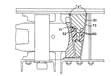
Acco~ling to the present invention shown in Figures 3-6, a "floating" gravity wedge 70
is h~col~lated into the comle~;lor asselllbly 10 wL~l~,ln the wedge is provided with an ~tt~rllrd
set of su~polling means 60 for vertically su~polling and holding the wedge in a position slightly
above a fully seated position when the comleclor assembly is under tensile or draft loads. It
should be made clear that all com~e~;lor assembly col~ollelll~ of the present invention will be
l~ f~,r~ ced using the same numerals as the prior art system, inrhl(ling the gravity wedge. As
previously described, a prior art "rigid" wedge 70 will have a nahural ten-l~nr.y to drop by
gravity within the pocket casting 40 when the dlawl,dr butt end 15 is pulled along the
longihl~lin~l aAis during tensile, draft loading. As desclil,ed, the col~l-eclor assembly
components will sepalate or stretch, allowing the wedge to fall into the slack or space created
upon ~ tehillg. This dro~ped position is considered a first seated position. While in the first
` CA21 56657
-
seated position, the weight of the wedge will cause front wall 71 and back wall 73 to
~spéclively push against sllrfrqres 52 and 42 and take-up the available free slack between the
col~lle~;lol colll~ol~nls. However, removing the free slack while the railcar is being pulled and
under tensile loading is not desirable because a rigid gravity wedge will remain in this first
seated position and "lock-in" most of the tensile loads applied to the connector through the
seating action. The locked-in forces are additive in nature to C(Jl11~ 7SiVt; loads that are later
. ;~ e~1 when the tMin is being pushed and under colll~l~,ssive loading. De~ lly, the
additive forces accelel~le CGlll~ wear and create higher lateMl dlawl,ar angling forces
which may COlltlilJUI~ to wheel lift.
The present invention on the other hand, pl.,~.,.ll~7 the wedge from falling into the first
seated position during tensile loading beca.lse the ~u~pollillg means 60 which is provided in the
front and back walls 71 and 73 of the wedge, ~yllllll~ ally ~ai~ in~ the wedge in a holding
position slightly above the first fully seated position. As the Figures 3-6 show, the means 60 is
resilient and protrudes slightly beyond the walls 71,73 of the wedge so that a small amount of
controlled gap, herein desi~ ~d as "X", l.,.~,aills bclwæll the wedge walls and the adjqcent
snrfq~s. In this case, the ~ ent S~ r~eS will be the follower block rear surface wall 52, and
the pocket casting rear sloped wall 42 and it is plefclable that the controlled gap "X" be about
0.125 inches.
Figure 3 shows that the wedge can be provided with a single supporting means on each
of the front and back walls, or it can colll~lise multiple supporting means on both walls. For
~ le, Figures 4 and 5 show that the multiple su~olllng means could consist of two
h~ o"~lly or two vertically aligned and spaced means, or it can consist of more complicated
multiple sets of means like that of Figure 5, where the wedge is shown as having four
~ul~pollillg means 60 on each front and back wall 71,73. The actual size, location, and the
number of supporting means used for SU~PO1l111g wedge 70 is not crucial to the operation of the
invention as long as the ~7u~olLillg means has the capability to keep the wedge from fully
seating and relatively square within the pocket casting during tensile loading. It is envisioned
that the ~iu~ollillg means 60 of the plcfell~d embodiment be colll~ised of an e~ lic
mqt~ l having spring-like ch&l...;t~ I;c~. For example, Figure 4A shows wedge 70hlcOl~olàlil~g an e1~lo,l~ri( spring means 62 operably functioning as each supporting means
60, ~l~reill each clast~ ,lic means 62 is l~ceived into a blind bore 85, which is formed on
CA21 56657
:
each wall of wedge 70. The bores 85 can either be cast as part of the wedge or later m~r~in~d
into it. Each blind bore has a bore inlet 86, bore sidewalls 88, and a bore base 87. The depth
of each bore is interrelated to the co~ ssion chala.;t~ ics of the chosen supporting means
60, which in this case, is a function of the co-ly?l~ ibility of the elastomeric supporting spring
62. This is best nntlerstQod by ~cfell~g to Figures 4A and 6, where "D" is the tli~m~ter of
bore 85 if a round hole is used, and "H" is the bore depth, with the colll~l. ssed state of the
e!z~lo...~ ;r, means 62 of Figure 6 being a function of the bore volume "V", described by the
formula V=3.141(D/2)2H. As Figure 6 illustrates, the ela~lolll~ic supporting means 62 has a
co~ ei,sed height equal to the depth "H" of blind bore 85, and an uncon~l~ ssed height of Ho~
where the ~ re dete ...il-~d by H-Ho should be equal to X", or the amount of the desired
controlled gap, which IS preferably 0.125 inches. It should be ulld._l~lood that the shape of
e!~l(,---rrir su~polling spring means 62 is more a function of the bore volume "V", mr~ning
that ~ o~ ric su~pollillg means 62 does not have to be limited to strictly ~;ylil~l ;r~lly-shaped
forms. Figure 6 illustrates this point where spring means 62 is shown having a base fli~ ter
of "D2", which is equal to bore ~ -"P~e~ "D", and an upper di~ " of "Dl", which is less
than the di~meter of "D2" to the extent that when the claslolne.ic spring means 62 is fully
col~3sed from height "Hol' to height "H", the bore hole volume "V" will almost be
col~letely filled by the elaslolll~.ic material bulging or ~ n~1in~ during col~lession.
1es the llnlimit~d profile choices available, it is also envisioned that the e~ rir
~u~pollillg means 62 can be secured within blind bore 85 through a number of dirr~le.ll ways.
For example, means 62 could be secured to base 87 by bonding, or it could be "press" fitted
into the bore 85 with the body of spring means 62 being tightly secured b~lw~en sidewalls 88,
or it even could be secured by using â peg on the base of the supporting means which engages a
compl~-m~nt~ry hole formed within bore base 87. In any event, once elaslome.ic ~u~polling
spring 62 is so ~'t~rh~1, it will extend Oul~.aldly beyond each wedge wall 71,73 in its
uncol,l~ ssed state by the desired controlled gap "X" and be at least partially complem~ont~ry in
shape to that of blind bore 85.
The :iU~)pOlling means of the present il~venlioll must also exhibit chaldc~.islics which
allow the wedge to fully wi~ l buff and shear loading experienced by the supporting means
and yet still have the capability of adj~ to the increased c~ nres (slack) created within
the comleclor assembly as the system wears. Th~,..,fole, it is preferable that the el~ctom~ric
`~ CA21 56657
sul)po~ g means be col~lised of mqteriql exhibiting a COlllpl~ SiVt; load rate belweell about
100,000 and 200,000 pounds per inch for inxtqlled pieces loaded in parallel. With these rates,
it is pr~f~.~ble that a ...;~ .. of two supporting means 62 and a mqximllm of four means per
side of wedge 70 be provided in order to pl~ .ll cocking or mi~q-li nmPnt of the wedge through
added stability. It is also desirable that the lateral shear rate of the elq.~Lo.~ ic material be
relatively high, say ~lwæn about 75,000 and 150,000 pounds per inch in order to pl~v~lll
sig~-irir~ shear deformation when protruding beyond the wedge face by the amount of the
controlled gap "X". It is also desirable that the mq~riql exhibit a value of about 40 to 60 in
dulolll~t~r when using the Shore D scale at a ~lll~c.alul~ of 70 F. This nPces.sA. ily means that
the e1~L~ ;r mqteriql must also be x..rri~ ie~.lly resilient at -40 F in order to follow a
colll~r~ssioll and release defollll~.lion through about 15% of its free or uncolllpl~ssed height
"H", at a cycling rate of about 5 hertz. It is also preferable that the chosen elaslollleric mqt~riql
have a coefficient of friction bclwæn about .3 and .5 as b~;lween the elaxlulllelic material and
the qdjacP-nt cast steel ~. r, ces. With these r~qr~ L.~ ;xl;rs~ each cla~lolll~.ic spring will fully
CO11YJ1~5 and not extend beyond wedge walls 71,73 at low mqgnihl~le loads, say as low as
20,000 pounds, or at high loads, say as high as 40,000 pounds. Under the fully colll~ssed
condition, the wedge 70 will operationally be equivalent to a "rigid" wedge device vvL~ the
wedge can again resume a fully seated position. However, is to be understood that this second
fully seated position is equivalent to the first fully seated position, except that the wedge and
comleclor assembly COlll~)OIl~ S are now under col~i~sive buff loading where the entire
loading t;~C. ;e ~r-ed by the follower block 50 will be Ll~r~ .l.,d into the wedge, and then
finally into the pocket casting 40. Under buff loading, the e1-q~lo.~ ;c m~teri~l colll~lishlg the
su~pol~ g means must also have cllqr~ct~prixtirs which make the wedge capable of wiLl.x~ uling
high colll~l~s;,ive loads without settling of the mq~riql once the load is re1Pæ~P~d. Settlin~ is a
condition where the C15~lu--~ - ;r spring will lose the ability to fully return to its original free-
osiLio~, in this case "Ho'l, after undelgoillg several tensile and Col~)l'eSSiVe cycles.
This means that when a buff load is releq~ed, the resilient supporting means should have the
capability to "feed out" to the original holding position such that wedge 70 is again retained in a
vertical position slightly above the first fully seated position. The wedge will remain in this
first seated position until the co~ e~;lor assembly again e~ -re~ its next buff or coll~ ,ssive
`- C A2 1 5 6~7
load, thereby eli...i~ the possibility of the wedge dr~i~ into the first seated position and
storing tensile forces within the connector asselllbly.
Figure 7 and 7A shows a second embo lim~-nt of the present invention, wll~ ;eill the
~ul~po~ g means 60 is colly?lised of a spring-loaded device or plunger assembly 170 instead of
the resilient ela~loll~ ic ~u~ollillg means. As the two figures show, the spring-loaded plunger
~uppollillg means 170 is colll~lised of a steel spring 175, either in the form of stacked Belleville
~,.dSl~, or as a single helical coil steel spring, a plunger keep 186 having a centrally located
orifice 189, and a plunger 180 that is in i.~ contact with steel spring 175. For the sake of
ssi~ this particular embo~1im~-nt lefe.el~e to "steel" spring should be understood to
ellcol~ass either type of spring shown in Figure 7 or Figure 7A. In either case, action of the
steel spring causes plunger tip 184 to project through orifice 189 for ~u~)pollillg contact with
either rear follower block surface 52 or sloped interior wall 42 of pocket casting 40, ~epen~ling
upon which side of wedge 70 each spring-loaded plunger assembly is positioned. The plunger
keep 186 has a generally geometric shape which is compl~ .y to the geometric shape of
each of the blind bores 85 and inrhllles a peliyL~ly 187 having .~h~ breads 188 to those
threads 88A ".~ in~1 into the sidewalls 88 of blind bores 85. It should be understood that
threads 88A are to be provided only at the bore inlet area 86, and are not to extend completely
to bore base 87. Plunger keep 186 functions as a means for holding spring assembly 170
within bores 85 when the keep is threaded into each of the bore inlets 86. Figure 7 illustrates
that each bore base 87 will support the steel spring 175, with the spring e~lelldi~lg u~w~ly
tOWaldS bore inlet 86 until it contacts bottom surface 185 of plunger keep 186. The steel spring
175 is sized such that there is very little tolel~l1ce ~lween the bore sidewalls 88 and the spring,
lll~l~y avoiding the need to ~"~Ai~ lly secure and plev~;lll the spring from moving within the
bore. It is also envisioned that with either type of steel spring, more than one spring will be
required in order to ~ ;-i-. wedge 70 in the holding position. As Figure 7 shows, several
Belleville ~. asl~ have been stacked within bore 85 as a means of achieving a high enough
spring rate for holding the wedge. ~ Ul;ve m.oth~ could include adding several bore and
plunger assemblies to each wall of the wedge; this method would be especi~lly well suited for
the helical coil situation.
Plunger tip 184 has a peli~ l shoulder 182 that is upwardly projected into abutting
contact with plunger keep bottom surface 185 through the action of spring 175. As plunger
g
- CA21 56~Y
keep 186 is threaded do~ l..~dly into bore 85, bottom surface 185 will contact and push
~h~ er 182 dOwllwald onto spring 175, thereby coulylesshlg the spring and causing plunger
tip 184 to lower itself through orifice 189 and retract further into the blind bore 85. In this
way, the controlled gap "X" bclwæll wedge 70 and the follower and pocket casting sllrf~res
52,42, l~ Dyeclivcly, can be adjusted by threading plunger keep 186 either inwardly or uulwardly
within blind bore 85. Plunger tip 184 is preferably coll~ylised of a solid piece of elaDlolll~lic
m~trri~l having a ~ onal size and cGl~ y shape to orifice 189 at its upper portion,
while the ~h-n~ er 182 is slightly smaller in ~limrn~ional size to bore 85. Like the ela~lolll~lic
suyyolling means of the yl~fc~l~,d embollimPnt the elq~lo.~f . ic plunger tip 184 of this
embo~liment will fully CO111Y1~DS within bore 85 whenever a co ~l~SSiVC or buff load is
c~licnced, and when that load is rel~ , each plunger tip 184 will support and ~
wedge 70 in the holding position by action of spring 175 pushing plunger 180 ~ul~ar~ of bore
85. It is also prerelab'.e that plunger tip 184 exhibit the same colllylession and shear loading
~ s, as well as the same ~.luion~tel and coefficient of friction plopellies of the ela~lomelic
m~t.o.riql of the y~fell~d embo~lim~nt When using either of the supporting means embo-1i...
just disclosed, the lateral dlaw1~ar angling forces on the
conn~ assembly will be greatly re~ ced. This will aid in pl~leclil g the conl-~c~ g
assembly colllyollelltD from pre-mature wear, thereby h~cl~,asmg their operational lives.
The folegoillg details have been provided to clesçrihe the best mode of the invention and
further variations and mo~lifir~tif~ns may be made without deyallhlg from the spirit and scope of
the invention, which is defined in the following claims.
-10-