Note: Descriptions are shown in the official language in which they were submitted.
w ogS/19721 2 ~. 5 ~ PCT/US95/00813
WHEELED LUGGAGE WITH CARRYING HANDLE
This invention relates to wheeled luggage and
more particularly, to a new and improved ~ hly of
a maneuvering and carrying handle and an auxiliary
luggage attachment and handle restraint which allows
the handle to be extended to selective different
lengths for carrying or maneuvering the luggage and
which allows the auxiliary luggage to be attached
for transportation on a face panel of the main
luggage as it is maneuvered on its wheels.
Backqround of the Invention
One of the most popular recent conveniences in
the field of wheeled luggage is exemplified in U.S.
Patent No. 4,759,431, assigned to the assignee
hereof. This type of luggage includes a luggage
case with wheels aligned on a common axis along one
bottom edge of the case. An extendable pull handle
is connected to the case. The user extends and
grasps the pull handle, levers the case into a
position where only the wheels touch a support
surface, and pulls the case on its wheels by the
extended handle. With the case levered into this
rolling position, much of the weight of the case is
balanced over the wheels so very little effort on
the handle is required to maintain the case in the
rolling position. The wheels withstand most of the
weight, and it is very easy to move the case.
Because the wheels are located along a common
rotational axis at one bottom edge of the case, the
case is also very maneuverable. After pulling the
d case on its wheels, the pull handle is inserted or
retracted into the case.
A conventional carrying handle separate from
the pull handle is available to carry the case in
the conventional manner, rather than roll it on its
WO 95/19721 ~ PCT/US95/00813
wheels. When carrying the case, the pull handle is
retracted to allo-~ the case to be carried with the
weight of the case and its contents suspended from
the carrying handle in the conventional manner.
Rolling the case on its wheels and carrying the
case while suspended from the carrying handle are
essentially two separate functions. The carrying
handle must support the weight of the case and its
contents and do so in a way that maintains the
balance of the case so that it can be easily
suspended at the side of the person carrying it. In
order to balance the case for carrying, the carrying
handle must be located at the top of the case. The
carrying handle must also be connected internally to
a frame structure capable of supporting the weight
of the case and its contents.
On the other hand, the pull handle is not
intended for lifting the case, but is extended only
to maneuver the case on its wheels. The pull handle
must be sufficiently exten~Ahle and have a
substantial enough connection and interaction with
the case to allow the case to be tilted or levered
onto its wheels, to maintain the case in the
position over the wheels, and to direct the case by
pulling it. The pull handle should also have enough
strength to allow the case to be maneuvered up and
down stairs and over street curbs. For these and
other reasons, the pull handle is typically located
on the side of the case above the wheels and is
connected integrally enough with the case to
transfer the levering force throughout the case.
Connecting the pull handle to the case in this
manner is easier in a hard-sided luggage case than a
soft-sided luggage case. In a hard-sided case, the
relative rigidity of the case shells or halves
comprise part of the internal structure to support,
lever and pull the case by both the carrying handle
~ wos~ll972l 21 5 6 71 0 PCT~S95/00813
and the pull handle. However, in soft-sided cases,
the flexible exterior panels offer little or no
structural integrity, and therefore an internal
frame structure must be provided. The internal
frame structure can be somewhat extensive in order
to adequately accommodate a carrying handle, a
separate pull handle and the wheels. Generally, the
internal frame structure in soft-sided cases
re~uires structural members around the internal
periphery of the bag to support the weight of the
bag from the carrying handle. Structural members
are also required along one of the major exterior
face panels of the case to connect to and support
the pull handle. In some cases, the added
complexity of the internal frame structure to
provide both carrying and wheeled pulling capability
substantially diminishes the advantages of lighter
weight and flexibility associated with soft-sided
luggage.
Perhaps one of the most important conveniences
of wheeled luggage using an extendable pull handle
has been the incorporation of an auxiliary luggage
carrying capability. To obtain this capability, the
auxiliary luggage is attached to the wheeled main
luggage case and is supported on an upward facing
exterior face panel of the tilted main luggage case
when it is pulled on its wheels. The typical
attachment technique involves extending a hook,
strap or belt around the carrying handle of the
auxiliary case to suspend it against the upward
tilted exterior face panel of the main luggage case
while the main case is pulled on its wheels.
~ Most of the auxiliary luggage attachment
mPchAnic~c described in U.S. Patent No. 4,759,431
35 are functionally associated with the extendable pull
handle. An attachment strap is connected to the
pull handle and is exposed by the extension of the
WO95/19721 ~ PCT~S95/00813
pull handle from its retracted position. The
attachment strap is placed through the carrying
handle of the auxiliary luggage, and then connected
back to the pull handle near the point where the
user grasps the pull handle. Thus, the pull handle
must be extended to attach the auxiliary luggage.
If the attachment strap is not used to connect
to auxiliary luggage, it is placed or folded into a
middle portion of the pull handle. It is also
1~ necessary to place or fold the attachment strap into
the middle portion of the pull handle when
retracting the pull handle back into the interior of
the case. Attempts to retract the pull handle with
the attachment strap extended therefrom and
connected to auxiliary luggage can cause obvious
difficulties inconsistent with the intended
operation.
Furthermore, the extension of the attachment
strap from near the extended end of th~ pull handle
to the carrying handle of the auxiliary luggage case
may result in reduced stability of the auxiliary
luggage, possibly making it difficult to maintain
the position of the auxiliary luggage on the main
case as the case rolls over uneven terrain.
Furthermore, it may also be difficult to attach the
auxiliary case to the main case when the pull handle
is extended.
U.S. Patent No. 4,759,431 also discloses an
embodiment where the pull handle is separate from an
exposed auxiliary attachment belt. The exposed
attachment belt lacks the appeal and utility of the
combined pull handle and attachment belt because the
attachment belt is always exposed and poses the
possibility of disconnecting from the case when not
in use. Use of the separate attachment belt may
also become inconvenient because of its lack of
integrated functionality with the pull handle.
woss/1s721 ~15 6 71 0 PCT~S95/00813
It is with respect to these considerations and
others associated with wheeled luggage cases having
an extendable pull handle and auxiliary luggage
b attachment capability that the present invention has
evolved.
Summary of the Invention
Some of the important features of the present
invention include improving, simplifying and making
more convenient, the use of a wheeled luggage case
having a selectively extendable and retractable pull
or maneuvering handle and a restraint to attach
auxiliary luggage to the case and to support the
auxiliary luggage case on an exterior upturned face
panel of the main luggage case. More specifically,
the important features of the present invention
involve allowing the auxiliary luggage to be
attached to the case without ext~n~ing or using the
pull or maneuvering handle, using a single handle as
both a carrying handle and a pull handle, permitting
the handle to be extended a selected amount
intermediate of its maximally extended position to
either pull or carry the case, and selectively
fixing the extendable and retractable handle in the
best position for a particular user to pull the
luggage case on its wheels.
Some of the important features of the present
invention include improving, simplifying and making
more convenient, the use of a wheeled luggage case
having a selectively ext~n~Ahle and retractable pull
or maneuvering handle and a restraint to attach
auxiliary luggage to the case and to support the
auxiliary luggage case on an exterior upturned face
panel of the main luggage case. More specifically,
the important features of the present invention
involve allowing the auxiliary luggage to be
attached to the case without extending or using the
pull or maneuvering handle, using a single handle as
wo9sll972l 2 t ~ PCT~S95/00813
both a carrying handle and a pull handle, permitting
the handle to be extended a selected amount
intermediate of its maximally extended position to
either pull or carry the case, and selectively
fixing the exten~hle and retractable handle in the
best position for a particular user to pull the
luggage case on its wheels.
To achieve these and other important aspects,
the present invention relates to a new and improved
handle and restraint assembly for carrying and
maneuvering a main luggage case having wheels. A
handle is connected to the case and is selectively
extendable into a fully extended position, a fully
retracted position, and a selected intermediate
position between the fully extended and the fully
retracted positions. The handle includes a
handpiece for gripping the handle to carry the case
and to maneuver the case on the wheels. A restraint
device is operatively connected to the handle to
selectively restrain the handle in the fully
extended position in which to maneuver the case on
the wheels and in a intermediate position for
carrying the case. The restraint device is also
capable of selectively restraining the handle in an
intermediate position for pulling the case on the
wheels. The restraint device may include a
selectively ext~n~Ahle elongated flexible element
for connecting an auxiliary luggage case to the main
case to carry the auxiliary case on the main case
when maneuvering the main case on the wheels. The
elongated flexible element is ext~n~hle for
connection to the handle, and may restrain the
handle in an intermediate position for carrying the
case or for pulling the case on the wheels. A first
clutch mechAn;sm may be operatively connected to the
elongated flexible element for controlling
extension, retraction and retention of the elongated
~ 2 ~ 0
WO95/19721 PCT~S95/00813
flexible element, and a second clutch mechanism may
be operatively connected to the handle for
controlling extension, retraction and retention of
the handle. The first and second clutch m~h~;sms
are separately operable to independently control the
extension, retraction and retention of the elonyated
flexible element and the handle, respectively, or
they are interoperatively connected to
simultaneously control the extension, retraction and
retention of the elongated flexible element and the
handle, respectively.
To achieve the above and other important
aspects, the present invention relates to a new and
improved method of carrying and maneuvering a main
luggage case having wheels. The method involves
connecting a handle to the case to for moving to a
fully extended position, to a fully retracted
position, and to a selected intermediate position
between the fully extended and the fully retracted
positions. The method also involves restraining the
handle in the fully extended position and
maneuvering the case on the wheels while the handle
is restrained in the fully ext~n~e~ position,
restraining the handle in a selected intermediate
position and carrying the case by the handle while
the handle is restrained in the intermediate
position, and restraining the handle in the fully
retracted position when not carrying the case and
maneuvering the case on the wheels. The case may
also be maneuvered or pulled on the wheels while the
handle is restrained in the selected intermediate
position. An elongated flexible element may be
selectively extended from the case, connected to an
auxiliary luggage case, and the auxiliary case
carried on the main case when maneuvering the main
case on the wheels. The elongated flexible element
is connected to the handle to restrain the handle in
WO 95/19721 ~ PCT/US95/00813
an intermediate position for carrying the case or
for maneuvering the case on the wheels. The
extension, retraction and retention of the elongated
flexible element is controlled by restraining the
S flexible element, and the extension, retraction and
retention of the handle is controlled by restraining
the handle. The extension, retraction and retention
of the elongated flexible element may occur
independently of or simultaneously with the
extension, retraction and retention of the handle.
A more complete appreciation for the various
improved aspects and features of the present
invention, the nature of the present invention
itself, and the scope of the present invention can
be obtained from the following drawings which are
briefly summarized below, from the following
detailed description of a presently preferred
embodiment of the invention, and from the appended
claims.
Brief Descri~tion of the Drawinas
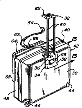
Fig. 1 is a perspective view of a wheeled
luggage case incorporating an assembly of a
selectively positionable maneuvering and carrying
handle and an auxiliary luggage attachment and
handle restraint device in accordance with the
present invention.
Fig. 2 is an enlarged partial perspective view
of the assembly of the handle and restraint device
shown in Fig. 1.
Fig. 3 is a partial end elevational view of the
luggage case shown in Fig. 1, with the maneuvering
and carrying handle in a partially extended position
similar to that shown in Fig. 2.
Fig. 4 is a perspective view similar to that
shown in Fig. l, taken from the opposite perspective
and showing the case on its wheels, illustrating the
pull handle and restraint device connected together
WO95/19721 ~1 5 6 71 0 PCT~S95/00813
and in an intermediate extended position for pulling
the case.
Fig. 5 is a perspective view of the luggage
case shown in Fig. 1, illustrating the handle in a
fully extended position and the restraint device in
an independent fully retracted position.
Fig. 6 is a perspective view similar to Fig. 5
illustrating the extension of a belt of the
restraint device to connect a piece of auxiliary
luggage to the main luggage case.
Fig. 7 is a perspective view of the luggage
case shown in Fig. 6, taken from an opposite
perspective, showing the main case on its wheels,
the auxiliary luggage case supported on the main
case, and connection of the auxiliary luggage case
to the main luggage case by the belt of the
restraint device.
Fig. 8 is a partial section view with a portion
broken out of the main luggage case, taken
substantially in the plane of line 8-8 of Fig. 1.
Fig. 9 is a partial side elevational view, with
a portion broken out, of the handle and restraint
device shown in Fig. 8.
Fig. lO is a partial section view taken
substantially in the plane of line 10-lO of Fig. 5.
Fig. 11 is a partial section view taken
substantially in the plane of line 11-11 of Fig. 9.
Fig. 12 is a partial section view with a
portion broken out, taken substantially in t~he plane
of line 12-12 of Fig. 9.
Fig. 13 is a view similar to a portion of Fig.
12, showing the restraint device holding the handle
- in its maximally extended position.
Fig. 14 is a view similar to Fig. 13 showing
- 35 the release by the restraint me~hAnis~ of the handle
to allow it to retract.
WO95/19721 PCT~S95/00813 ~
7 ~ ~
Fig. 15 is a partial section view taken
substantially in the plane of line 15-15 of Fig. 8.
Fig. 16 is a section view taken substantially
in the plane of line 16-16 of Fig. 15.
Fig. 17 is a section view taken substantially
in the plane of line 17-17 of Fig. 15.
Fig. 18 is a section view taken substantially
in the plane of line 18-18 of Fig. 17.
Fig. 19 is a section view taken substan~ially
in the plane of line 19-19 of Fig. 15, illustrating
the restraint of the restraint device to prevent the
belt from extending.
Fig. 20 is a section view similar to Fig. 19
illustrating the release of the restraint device to
allow the belt to extend.
Fig. 21 is an exploded perspective view
illustrating the major elements of the restraint
device shown in Figs. 15 to 20.
Fig. 22 is a partial perspective view of an
optional feature of the handle of the assembly shown
in Figs. 8, 9, 11, 12 and 21.
Fig. 23 is a partial section view through a
portion of Fig. 22, illustrating one condition in
solid lines and another condition in partial
phantom.
Fig. 24 is a partial section view similar to
Fig. 23, illustrating another position of the
elements shown in Fig. 23.
Detailed Description
The present invention is embodied in an
assembly 30 of a selectively extendable and
retractable maneuvering and carrying handle 32 and
an auxiliary luggage attachment and handle restraint
device 34, as is shown generally in Figs. 1-3. For
convenience, the improved and interactive assembly
30 will be referred to herein as a handle and
restraint assembly 30.
WO95/19721 215 6 71~) PCT/US95/00813
The handle and restraint assembly 30 is
preferably housed in a cassette 36. The cassette 36
is connected to a major external face panel 38 and a
top side 40 of a main luggage case 42. Wheels 44
are attached to the case 40 at an edge defined by
the intersection of the exterior face panel 38 and a
bottom side 46 of the case 42. The wheels 44 are
positioned on the case 40 to rotate about a common
rotational axis, preferably one extending
transversely between ends 48 and 50 of the case.
The case 42 may be either of the conventional
hard-sided construction having two relatively rigid
external shells which face one another and are
hinged together along the bottom side 46, or of a
soft-sided construction (not shown) utilizing
relatively flexible exterior panels for the face
panels, sides and ends. In a soft sided
construction the cassette 36 and the wheels 44 are
operably connected to an interior frame structure
which provides support for the case including the
flexible exterior panels.
The maneuvering and carrying handle 32 is
selectively extendable from the cassette 36, as is
shown in Figs. 2-4. With the handle 32 in an
extended position, the case 42 is levered onto its
wheels 44 to a rolling position by a user gripping
the extended handle 32. The degree of tilting or
levering of the case 42 preferably places the
majority of the weight of the case over the wheels
44. Tilted in this manner, very little effort is
required by the user to maintain the case over the
wheels 44. The user then pulls on the extended
handle to move the case on its wheels along a
support surface.
The handle and restraint assembly 30 allows the
handle 32 to be selectively extended a relatively
small distance, such as that shown in Figs. 2 and 3
WO 9S/19721 PCT/US95/00813
æ~ ~71~
and used in this position as a carrying handle for
lifting and suspending the case. When the handle 32
is used as a carrying handle, a belt 52 with a hook
54 at its outer end extends from the restraint
device 34 in the cassette 36 to the handle 32 and
restrains the handle from further extension.
Restrained in this manner, the application of
lifting force on the handle 32 allows the case 42
and its contents to be lifted and supported by the
handle 32.
Normally the belt 52 of the restraint device 34
will be connected to the handle 32, even when the
handle 32 is in the fully retracted position shown
in Fig. 1. In the retracted position, the restraint
lS device 34 prevents the inadvertent extension of the
handle 32 as might otherwise occur during handling
of the case 42. Alternatively, the belt 52 can
remain in the retracted position when the handle 32
is in the extended position. A slot 55, as shown in
Fig. 10, is formed in the cassette 36 into which the
hook 54 can be inserted and connected to maintain
the hook 54 in a retracted position regardless of
the extended position of the handle.
To extend the handle 32, a belt release lever
56 must be pivoted by the user, as shown in Figs. 2
and 6. Pivoting the belt release lever 56 releases
the belt 52 of the restraint device 34 to allow the
belt to extend from or retract into the cassette 36.
As soon as the desired extended position is
achieved, the belt release lever 56 is released, and
further extension of the belt 52 from restraint
device 34 is prohibited. Similarly, in order to
retract the belt 52 into the restraint device 34
from an extended position, the belt release lever 56
is again lifted or pivoted. With no restraint on
the belt 52, it will retract into the cassette 36,
WO95/19721 " 2 1 ~ ~ ~ 1 0 PCT~S95/00813
as shown in Fig. 5, by operation of the restraint
device 34.
A handle release lever 58 is also connected to
the exterior of the cassette 36 and functions to
hold the handle 32 in a fully extended position and
- to release the handle from the fully extended
position. In the fully extended position, the
restraint device 34 operably contacts rods 60 which
extend from and retract into the cassette. The rods
60 are connected at their outer end to a handpiece
62, thus completing the handle 32. The operable
contact between the restraint device 34 and the
handle rod 60 is maintained until the handle release
lever 58 is pivoted upward as shown in Fig. 2. Upon
pivoting the handle release lever 58, the operable
retention established by the restraint device 34 and
transmitted to the handpiece 62 by the belt 52 and
the hook 54 is also released, because pivoting the
handle release lever 58 also pivots the~belt release
lever 56. With the belt release lever 56 pivoted in
conjunction with the handle release lever 58, the
restraint supplied by the restraint device 34
through the belt 52 is terminated.
The independent operation of the handle 32 and
restraint device 34 by lifting the release levers 56
and 58 advantageously allows the belt 52 to be
extended selectively and independently for the
convenience of easily attaching an auxiliary luggage
case 64 as shown in Fig. 6. The auxiliary luggage
case 64 is placed next to the main luggage case 42,
and the belt 52 is extended through a carrying
handle 66 of the auxiliary case 64. Either before
or after the extension of the belt 52, the handle 32
is extended to its maximally extended position.
Once the belt 52 has been extended through the
carrying handle 66, the hook 54 is connected to the
handpiece 62 in the manner shown in Fig. 7. With
WO95/19721 21~ 6 ~1 0 PCT~S95/00813
the auxiliary luggage case 64 connected in this
manner, with the belt 52 and the handle 32 in their
extended position, the main luggage case 42 is
levered onto its wheels 44 to lift both the
auxiliary case 64 and the main luggage case 42 and
to support the auxiliary case 64 on the upturned
tilted exterior panel 68 of the case 42 while the
case is pulled on its wheels 44 by the handle 32.
The belt 52 can be selectively retracted into the
cassette 36 when no auxiliary luggage is attached or
connected and the handle 32 is in the maximally
extended position, as shown in Fig. 5.
Details concerning the handle 32 of the handle
and restraint assembly 30 are best understood by
reference to Figs. 8-14 and 21. The handpiece 62
includes a center grasping portion 70 which is
located over the top side 40 at a position generally
near the center of the case. With the grasping
portion 70 located in this manner, the case is in a
relatively balanced condition when the user grasps
the handpiece 62 to lift the case and carry it by
the handle 32.
An attachment portion 72 of the handpiece 62
includes a rectangularly shaped socket 74 into wh~ch
the upper ends of the rods 60 are retained,
preferably by pins 76 (Fig. 21). Near the middle of
the attachment portion 72, a receptacle 78 (Fig. 21)
is formed. The receptacle 78 is shaped to receive
the hook 54 attached to the end of the belt 52. The
hook 54 connects to and is received within the
receptacle 78. To release the hook 54 from the
handpiece 62, or from the slot 55, a flap 80 (Fig.
10) on the outer end of the belt 52 is grasped ~y
the user to lift the hook 54 off of the receptacle
78 or out of the slot 55.
A rectangularly shaped restraint sleeve 82 is
attached to the lower end of each of the rods 6~,
WO95/19721 2 l567 la PCT~S95J00813
preferably by a pin 84 (Figs. 9 and 21). The
restraint sleeves 82 interzct with a restraint
member 86 attached on the inner side of the handle
release lever 58, as shown in Figs. 9 and 12-14.
With the handle 32 in the retracted position shown
- in Figs. 9 and 12, the restraint member 86 contacts
and the exterior surface of the rods 60. When the
handle 32 is extended to its maximally extended
position, the restraint sleeves 82 ride over the
restraint members 86 and the restraint members
extend beneath the restraint sleeves 82 as shown in
Fig. 13, thereby restraining the handle 32 in the
maximally extended position.
To release the handle 32 from the maximally
extended position, the handle release lever 58 is
pivoted outward as shown in Fig. 14. In this
pivoted position the restraint members 86 move away
from the bottom of the rods 60 and the restraint
sleeves 82, thereby releasing the mechanical
connection of the restraint device 34 to the handle
32, and allowing the handle to move to the retracted
positlon .
Each rod 60 is retained for movement within a
tube 88, as shown in Fig. 11. Each tube 88 is
formed in a general rectangular configuration of a
size slightly larger than the exterior size of the
restraint sleeves 82. Consequently the restraint
sleeves 82 and the rods 60 can move along the length
of the tubes 88. The tubes 88 are part of an
internal structural component 90 of the cassette 36.
The structural component 90 and the tubes 88 extend
along the exterior face panel 38 on the interior of
the case 42. On the inside of the case, a fabric or
other suitable covering 92 hides the structural
- 35 component so and other elements of the cassette 36
from the user's view. In soft-sided luggage cases,
the structural element 90 may form an important
WO 9~i/19721 PCT/US95rO0813
21~6710
integral portion of the internal frame structure
necessary to support the exterior flexible panels in
such soft-sided luggage.
Each tube 88 includes an upper portion 94
having a rectangular cross-sectional shape which is
slightly larger than the rectangular cross-sectional
size of the rods 60, but not as large as the
rectangular cross-section of the restraint sleeves
82, as shown in Figs. 12-14. Consequently, the
restraint sleeves 82 contact the upper portions 94
to prevent the handle from extending beyond its
~Yi r~ lly extended posit-on (Fig. 13). In this
position, the restraint member 86 on the handle
release lever 58 also contacts the bottom of the
restraint sleeve 82, thereby rigidly fixing the
handle 32 in its maximally extended position. Since
the handle 32 cannot move further outward or inward
in this position, the main luggage case 42 can
easily be pushed by pushing on the handle 32 as well
as being pulled in the conventional manner.
The restraint sleeve 82 and the tubes 88 may
optionally include a resilient tab 91 and detents 93
and 95, as shown in Figs. 22-24. The resilient tabs
91 on each restrain sleeve 82 extend inwardly toward
the restraint sleeve 82 on the other rod 60. The
detents 93 are formed in the tubes 88 at a position
to receive the tabs 91 when the handle 32 is in a
fully extended position (Fig. 23). The detents 95
are formed in the tubes 88 at a position to receive
the tabs 91 when the handle 32 is in a fully
retracted position. The engagement of the resilient
tabs 91 with the detents 93 and 95 assist in
securing the handle 32 in the maximally extended and
fully retracted position, respectively.
Shoulders 97 are formed in the tubes 88 below
the upper detents 93 and above the lower detents 95.
The shoulders 97 cause the tabs 91 to compress
WOg5/19721 2 ~ 5 6 7 1 0 PCT~S95100813
inwardly as shown in Fig. 24 when the restraint
sleeves 82 move into adjacency with the shoulders
97. The added force from compressing the tabs 9l to
move them from the detents 93 and 95 over the
shoulders 97 creates an additional force to maintain
the position of the handle 32. However the added
force from compression of the tabs 9l can be
overcome with reasonable manual effort when
retracting or extending the handle from the fully
extended and fully retracted positions.
The tabs 9l also engage the sidewall of the
tubes 88 with a frictional force when the handle is
in an intermediate position between the fully
extended and the fully retracted positions, as shown
in phantom in Fig. 23. In the intermediate
positions the tabs 9l experience a lesser amount of
compression compared to that shown in Fig. 24.
However the tabs 9l create an adequate amount of
frictional force with the tubes 88 to maintain the
rods 60 and handle 32 in a free st~n~l;ng
intermediate position between the fully retracted
and extended positions. This frictional force in
the intermediate position alleviates the problem of
the handle 32 and rods 60 retracting into the
cassette 36 under the weight of the handle or ~rom
some other small force. As discussed below, the
contact of the restrain member 86 with the rods 60
also contributes to or achieves sufficient
frictional force to retrain the handle 32 in the
intermediate positions.
Details concerning the restraint device 34 of
the assembly 30 are best understood by reference to
Figs. 8 and 15-2l. The primary components of the
restraint device 34 are located behind an exterior
~ 35 of the cassette 36, generally in the vicinity of the
intersection of the external face panel 38 and the
top side 40 of the case 42, as well as behind the
WO95/19721 PCT~S95/00813
belt release lever 56 and handle release lever 58.
The major components of the restraint device 34
include the belt 52, a belt take-up roller 96 upon
which the belt 52 is coiled in both the extended and
retracted positions of the belt, a belt clutch
mech~;sm 98 which operably controls the extension
and retraction of the belt 52 by allowing it to
extend and retract and to restrain it in position,
the belt release lever 56 which interacts with and
forms a part of the belt clutch mechanism 98 to
establish a free movement condition and a restrained
condition of the belt, a handle clutch mechanism lO0
(Fig. 13) which includes the handle release lever
58, the restraint member 86 formed on the back side
of the handle release lever and the restraint sleeve
82 attached to the lower end of each rod 60 of the
handle 32.
As is shown in Fig. 15, the back side of the
cassette 36 includes a number of partitions, walls
and other structural elements to position and hold
the major components of the restraint device 34.
These partitions, walls and other structural
elements are formed generally between the tubes 88.
The belt take-up roller 96 is formed generally
as a drum which is rigidly connected to a center
shaft 102. A roller pulley 104 is also connected to
the shaft 102 at a position adjacent to the roller
96. The pulley 104 is fixed to rotate with the
shaft 102 and the take-up roller 96.
A pivot shaft 106 extends generally parallel to
the shaft 102. A pivot shaft pulley 108 is
rotationally connected on the pivot shaft 106 in
transverse alignment with the pulley 104. The pivot
shaft pulley 108 is free to rotate about the shaft
106. An elongated spring member 110 is connected at
its ends and is counter wound around the roller
pulley 104 and is forwardly wound around the pivot
~ WO 95/19721 2 1 5 6 ~ 1 0 PCT/u~S~Q0813
' ' ' i~ '` r' . "
shaft pulley 108, respectively. As is shown in Fig.
.6, the spring member 110 is wound in a clockwise
direction around the pivot shaft pulley 108. The
spring member 110 is bent in a permanent spring
deformation to normally coil in the clockwise
direction around the pivot shaft pulley 108, as
shown in Fig. 16. When the spring member 110 is
wound around the roller pulley 104, the direction of
coiling is also in the clockwise direction, but is
in a reverse or counter wound manner compared to the
spring deformation of the spring member 110. The
roller pulley 104, pivot shaft pulley 108, and
spring member 110 configuration form a constant
force spring.
As a consequence of the spring deformation of
the spring member llo, the pivot shaft pulley 108
will normally attempt to rotate in the clockwise
direction as shown in Fig. 16. The roller pulley
104 will normally attempt to rotate in a_
counterclockwise direction, and while doing so
rotate the belt take-up roller 96 with it. With the
belt take-up roller 96 normally biased by the spring
member 110 to rotate in the counterclockwise
direction as shown in Fig. 17, the belt 52 will
normally coil on the roller 96 in a manner to
retract. This retraction occurs when the belt
clutch mechanism 98 allows the belt to coil on the
roller 96. The spring member 110 provides the
tension force necessary to bias the belt 52 into and
toward retraction.
The spring member which is forwardly wound
around the pivot shaft pulley 108 and which is
reverse wound around the roller pulley 104 creates a
substantially constant tension force when the belt
clutch mechanism 98 is released. The constant
spring force achieved by the pulleys 104 and 108 and
the spring member 110 is a convenience to the user
2 1~ 6 ~ 1~ PCT/US95/00813
as the belt is extended, since the same force is
required to extend the belt both a slight distance
as well as a greater distance. In addition, the
belt may be retracted with a relatively cons~ant
force.
The belt clutch mechAnism 58 includes a star
shaped roller 112 which extends parallel to the
shafts 102 and 106. The star roller 112 is allowed
to freely rotate on a center shaft 113, and rotates
in conjunction with the movement of belt 52, which
extends over the star roller 112. Axially extending
indentions 114 are formed in the exterior surface of
the star roller 112 to give it the star shaped
appearance in cross-section.
A pawl 116 extends from the belt release lever
56 at a position to contact the belt 52 and force
the belt into one of the indentions 114, when the
belt release lever 56 is in a non-pivoted position
as shown in Figs. 17 and 19. The belt release lever
56 is connected to and pivots about the shaft 106.
The location of the end of the pawl 116 relative to
the center shaft 113 and the axis of rotation of the
star roller 112 forms an off-center restraint, as
shown in Fig. 19. Since the star roller 112 will
normally rotate in the counterclockwise direction as
shown in Fig. 19, and because the end of the pawl
116 which contacts the belt in the axial indentions
114 is located rotationally prior to a centerline
between the shaft 106 and the center shaft 113,
further attempts to extend the belt 52 Will result
in increased restraint of the pawl against the star
roller 112. In this manner the star roller 112, the
pawl 116 and the belt release lever 56 cause the
belt clutch mech~n;sm 98 to restrain the belt 52
against further extension. It is a result of this
feature of the belt clutch m~c-h~n;~m 92 that allows
the handle 32 to function as a carrying handle for
~ 21~6710
wosstlg72l PCT~S95/00813
the case. The belt clutch mechanism 92 sustains all
of the weight of the case and its contents which is
transferred through the belt 52 to the handpiece 62.
Although the off-center arrangement of the pawl
116 in the indentions 114 is primarily effective for
restraining further extension of the belt 52, it is
also effective in preventing retraction of the belt.
The deformation of the belt 52 by the pawl 116 into
one of the indentions 114 provides a sufficient
lo force to inhibit retraction. However, the
retraction restraint force is not nearly as
effective or substantial as the restraint applied
against extension of the belt.
To release the restraint applied on the belt
52, the belt release lever 56 is pivoted outward as
shown in Fig. 20. In the pivoted position shown in
Fig. 20, the end of the pawl 116 is withdrawn away
from the belt 52 and out of the indentions 114 in
the star roller 112. In this unrestrain~d
condition, the belt 52 can be extended or retracted
against the force applied by the spring member 110.
A pair of braces 118 extend inwardly from the
exterior of the cassette 36 as shown in Fig. 17.
The braces 118 each have an arcuate end 119 shaped
to follow in close clearance to the exterior round
surface 121 of the take-up roller 96. The braces
118 guide the belt 52 during retraction and
extension to help insure proper alignment while
being reeled onto or off of the take-up roller 96.
The braces 118 also act as supports by abutting the
exterior surfaces 121 of the take-up roller 96 when
the force applied from the belt 52 onto the roller
96 is substantial. The arcuate shaped ends 119 of
the braces 118 engage the edges 121 and minimize the
deflection of the take-up roller 96 when the roller
96 is slightly deflected in position.
WO95/19721 ~ PCT/U~J~ 13
1he ~a~ release lever 58 is also pivotally
connected about the shaft lC6. The handle release
lever 58 includes an outward extension 120 which
contacts a back surface of a lip 122 formed on the
lower end of the belt release lever 56, as shown in
Figs. 19 and 20. As a consequence, when a lip 124
of the lever 58 is gripped and pulled outward, the
extension 120 also contacts the lip 122 of the lever
56, causing both levers 56 and 58 to pivotjoutward
simultaneously. Since the belt clutch m~c~ni~cm 98
is released to allow the belt to withdraw when the
handle release lever 58 is pivoted outward (Fig. 2),
it is assured that the belt 52 will retract into ths
cassette 36 at the same time that the handle 32 is
retracted. Thus, there is no possibility that the
handle 32 will retract when the belt 52 does not,
unless the belt 52 is specifically restrained
against such retraction.
The belt release lever 56 is positi~ned within
an opening 126 formed in the handle release lever
58, as shown in Fig. 9. Positioning the lever 56 in
the opening 126 of the lever 58 thus allows both
levers 56 and 58 to pivot about the shaft 106. A
depression 128 is formed in the handle release lever
58 at a position below and behind the lip 122 on the
belt release lever 56 (Figs. 19 and 23). The
depression 128 allows the fingertips of the user to
be inserted behind the lip 122 to pivot the belt
release lever 56.
Similarly, a clearance 130 is formed in the
exterior surface of the cassette hPh; n~ and below
the lip 122 at the bottom end of the handle release
lever 58. The clearance 130 allows the fingertips
of the user to be inserted therein to contact the
lip 124 and pivot the handle release lever.
The handle clutch mech~n;sm 100 is established
by the handle release lever 58 and the restraint
-
WO95/19721 2 l 5 6 ~1 Q PCT~S95/00813
member 86 formed on the back of the release lever 58
opposite the depression 128. A sep~rate restraint
member 86 contacts each of the restraint sleeves 82
- attached to the bottom of each rod 60, when the
handle 32 is in its maximally extended position
(Fig. 13). When the handle release lever 58 is
pivoted outward, the restraint member 86 moves away
from and clears the restraint sleeve 82 to allow the
rods 60 of the handle 32 to be retracted into the
tubes 88, as shown in Fig. 14.
The release levers 56 and 58 are held in a non-
pivoted position by bias springs 132 and 134
respectively. Each bias spring includes a center
coil portion 136 which surrounds the shaft 106. The
ends of a lower arm portion 138 extending from each
of the center coil portions 136 of the bias springs
132 and 134 are connected respectively to the belt
release lever 56 and the handle release lever 58,
preferably by screws 140. Upper arm po~tions 142
which extend from the center coil portions 136 of
each bias spring 132 and 134 are connected to a
rigid projection 144. The projection 144 is
connected to a fixed structural partition 146 of the
cassette 36.
The manner in which the arm portions 138 and
142 are deflected by the coil portions 136 cause the
release levers 56 and 58 to be biased toward the
clockwise position as shown in Figs. 16, 17 and 19.
However, the force applied from the bias springs 132
and 134 is not sufficient to prevent the user from
conveniently pivoting the release levers 56 and 58.
When the handle 32 is extended to any position
less than maximum extension, the bias force on the
handle release lever 58 from the spring 134 causes
the restraint members 86 to frictionally engage the
sides of the rods 60 with enough restraint force to
keep the handle 32 from retracting into the cassette
WO95~19721 PCT~S95/00813
2~.3~
36 under the weight of the handle and rod. Thus the
- frictional force from the contract of the restrain
members 86 with the rods 60 supplements the force
from the slightly compressed tabs 91.
s From the foregoing description, it is apparent
that the assembly 30 of the handle 32 and restraint
device 34 offers numerous advantages with respect to
the extension and retraction of a single carrying
and maneuvering handle and with respect to the
lo extension and retraction of the auxiliary luggage
attachment belt 52. Because the restraint device 34
allows the handle to be selectively positioned at
intermediate locations between its retracted and
maximally extended position, the handle 32 can be
used as a carrying handle. The shape of the
handpiece 62 positions the grasping portion 70 near
a central location of the case to allow it to be
~alanced while carried by hand. The intermediate
extended positions of the handle allow ~he user to
conveniently adjust the handle to an optimal length
short of its ~ully extended position while pulling
the case on its wheels. When the handle 32 is in
its maximally extended position, the belt 52 can be
connected to it or it can be released to its
retracted position. With the handle in its
r~X;~lly extended position, the restraint device
fixes the position of the handle so that the case
can be maneuvered by either being pulled or pushed
on its wheels.
The independent release and control of the
attachment belt allows the to be extended and
connected to the auxiliary luggage without the
necessity of extending the handle. However, once
the handle is extended and the hook end of the belt
is connected to the handle, the position of the
auxiliary luggage on the exterior upturned face of
the main luggage case can be adjusted by taking up
WO95/19721 2 15 G7 1 PCT~S95/00813
excess slack in the belt, and the belt clutch
mechAnism restrains the luggage in that position.
Both the attachment of the auxiliary case and its
- support on the main case are facilitated by the
independent control over the extension and
retraction and the restraint of the belt 52. The
use of two separately operable yet interconnected
release levers 56 and 58 allows complete control
over both the handle 32 and the belt 52 in all of
the retracted and extended positions which they may
assume.
A presently preferred embodiment of the
invention and its many improvements and features
have been described with a degree of particularity.
This description is of the preferred example for
implementing the invention. The scope of the
invention should not necessarily be limited to this
description, but instead should be defined by the
scope of the following claims.