Language selection

Search

Patent 2156913 Summary

Third-party information liability

Some of the information on this Web page has been provided by external sources. The Government of Canada is not responsible for the accuracy, reliability or currency of the information supplied by external sources. Users wishing to rely upon this information should consult directly with the source of the information. Content provided by external sources is not subject to official languages, privacy and accessibility requirements.

Claims and Abstract availability

Any discrepancies in the text and image of the Claims and Abstract are due to differing posting times. Text of the Claims and Abstract are posted:

  • At the time the application is open to public inspection;
  • At the time of issue of the patent (grant).
(12) Patent Application: (11) CA 2156913
(54) English Title: AN END PIECE FOR A RAIL VEHICLE SLACK ADJUSTER
(54) French Title: PIECE DE BOUOT POUR REGLEUR DE TIMONERIE DE VEHICULE FERROVIAIRE
Status: Dead
Bibliographic Data
(51) International Patent Classification (IPC):
  • B61H 15/00 (2006.01)
(72) Inventors :
  • KARLSSON, UNO (Sweden)
(73) Owners :
  • SAB WABCO HOLDINGS B.V. (Netherlands (Kingdom of the))
(71) Applicants :
(74) Agent: FETHERSTONHAUGH & CO.
(74) Associate agent:
(45) Issued:
(86) PCT Filing Date: 1994-03-01
(87) Open to Public Inspection: 1994-09-15
Examination requested: 2001-01-26
Availability of licence: N/A
(25) Language of filing: English

Patent Cooperation Treaty (PCT): Yes
(86) PCT Filing Number: PCT/SE1994/000166
(87) International Publication Number: WO1994/020348
(85) National Entry: 1995-08-24

(30) Application Priority Data:
Application No. Country/Territory Date
9300668-2 Sweden 1993-03-01

Abstracts

English Abstract


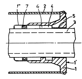
An end piece or barrel head (1) for a rail vehicle axial
slack adjuster is at its outer periphery connected to a barrel (2)
of the adjuster and is arranged around a rotatably and axially
movable tube (3). The end piece is provided with an internal,
circumferential groove (4), connected to the exterior by means
of a number of channels (5) opening in the end wall (1') of the
end piece for allowing water collected in the groove to freely
pass out to the exterior. The end piece is extended further into
the barrel by means of a sleeve (1"), which is connected to the
groove by means of notches (6) and contains a sealing ring (7)
engaging the tube and sealingly cooperating with the sleeve.


Claims

Note: Claims are shown in the official language in which they were submitted.


CLAIM
An end piece for a rail vehicle axial slack adjuster,
which end piece (1) is connected to a barrel (2) of the
adjuster at its outer periphery, is sealingly arranged
around a tube (3), which is rotatably and axially movable
relative thereto, and around the tube (3) is provided with
an internal, circumferential groove (4), which is connected
to the exterior by means of a number of channels (5)
opening in the end wall (1') of the end piece, c h a r a c-
t e r i z e d in that the end piece (1) is provided with a
sleeve (1"), which extends further into the barrel (2), is
connected to the groove (4) by means of notches (6) and
contains a sealing ring (7) engaging the tube (3) and
sealingly cooperating with the sleeve.

Description

Note: Descriptions are shown in the official language in which they were submitted.


215691~
W094/203~ ~ PCT1SE94100166


AN END PIECE FOR A RAIL VEHICLE SLACK ADJUS~N

Technical Field
This invention relates to an end pi~ce for a rail
vehicle axial slack ad~uster, which end piece i8 connected
to a barrel of the ad~uster at its outer periphery, iB Bea-
lingly ~rranged around a tube, which is rotatable and axi-
ally moveable relative thereto, and around the tube iB pro-
vided with an internal, circumferential ~Loo~e, which is
connected to the exterior by mean~ of a number of channel~
open i n~ in the end wall of the end piece.
Backu-ound of the Invention
Rail vehicle slack ad~usters work in an e~tr~mely
harsh environment underneath the vehicles, which mQans that
the sealing arrangements have to be effective BO as to pro-
tect all interior details against moist, water, snow, dust
and BO forth. The problem is ~nhan~ed by the extrQmely long
intervals ~et~aan interior services of the slack ad~ust~rs.
At end piec~s or barrel hQads for slack ad~ust~rs it
has earlier been custom~ry to provide as tight sealings as
possible between the tube and the ~nd piec~, for ~mpl~ by
means of two effective sealing rings in the ~nd piQce.
However, due to the mutual movQments b~tween the parts, a
certain undQr-pressure could be created insidQ th~ slack
ad~uster sucking moist, water and dust into the ad~uster
without any possibility to get out aqain. It goes without
saying that such contaminants inside the ad~uster can cause
harm.
A recently designed end piece of the kind defined
above, which is disclosed in Swedish Patent Application No.
9200180-9, i~ based on the different philosophy that the
creation of an under-pressure in~ide the ad~uster shall be
obviated and that any contaminants entering the end piece


CONFIRMATION
COPY

W094/203~ 215 6 913 PCTISE94/00166


around the tube shall be given the opportunity to leave
without qetting into the ad~u~ter itself.
The Invention
The results obtained by the design defined above sre
satisfactory. However, even improved re~ults may according
to the invention be obtained in that the end piece iB pro-
vided with a sleeve, which extends further into the barrel,
iB connected to the groove by means of notches and contains
a sealing ring engaging the tube and sealingly cooperatinq
with the sleeve.
This sealing ring i8 80 positioned within the sleeve
that it will not be displaced on the tube at normal rela-
tive axial and rotating mov~ments between the barrel and
the tube.
Brief Description of the Drawina
The invention will be described in further detail be-
low reference being made to the accompanying drawing, in
which Fig 1 iB and end-view of an end piece according to
the invention and Fig 2 is a side-viQw, psrtly in sectlon,
of an ax$al sl~ck ad~u~ter provided with such an end piece,
~hown in a section along the line II-II in Fig 1.
Detailed Description of a Preferred Embod~ment
A cylindrical end piece or barrel head 1 i~ at~Arhs~
to a tubulsr barrel 2 of a conventional axial ~lack ad~us-
ter for a railway vehicle. It is to cooperate with n rota-
t~bly and axially movable tube 3 and accordingly ha~ an
inner diameter corrQsponding to the outer diameter of this
tube 3.
At a certain di~tance from its end wall 1' the end
piece 1 iB provided with a circumferential groove 4 around
the tube 3 for collecting any contaminants (like water)
which have entered from the exterior slong the tube 3.
For sllowing these contaminants to freely leave the
- ~roove 4 there are a number of channels 5 connecting the
~ oove 4 with the end wall 1~. In the shown case there are

215 6 913 PCT/SE94/00166
wog4no3~


four channel~ 5, 80 that contaminants collected in the
groove 4 can freely leave through a chAnn~l 5 irrespective
of the angular position of the end piece 1. The inclination
of the channels 5 is chosen B0 that a free flow is guaran-
teed.
To the end piece 1 i~ fastened a Bleeve 1 n ~ which ex-
tends further into the barrel 2 and has nn end flangQ
~urro~lnAing the tube 3. The ~leeve 1" may be manufacturQd
of stainlQss material.
The groove 4 and the sleeve 1" ar~ connected by me~ns
of axial notches 6, preferably in line with the ch~nnsls 5.
Inside the sleeve 1" a sealing ring 7 i8 ela~t~c~lly
cl~mped on the tube 3 and cooperate~ ~ealingly with the
~leeve.
The position of the sealing ring 7 within the ~leeve
1~ is such that at normal axial and rotational relative
movements of the tube 3 ~nd the barrel 2 with its end piece
1, the 9~1 i ng ring 7 doQs not move on the tube 3, but only
at such extreme movements th~t occur at the replacQmQnt of
worn out brake ~hoe~ snd the like.


Representative Drawing
A single figure which represents the drawing illustrating the invention.
Administrative Status

For a clearer understanding of the status of the application/patent presented on this page, the site Disclaimer , as well as the definitions for Patent , Administrative Status , Maintenance Fee  and Payment History  should be consulted.

Administrative Status

Title Date
Forecasted Issue Date Unavailable
(86) PCT Filing Date 1994-03-01
(87) PCT Publication Date 1994-09-15
(85) National Entry 1995-08-24
Examination Requested 2001-01-26
Dead Application 2004-10-25

Abandonment History

Abandonment Date Reason Reinstatement Date
1998-03-02 FAILURE TO PAY APPLICATION MAINTENANCE FEE 1998-04-21
2003-10-24 R30(2) - Failure to Respond
2004-03-01 FAILURE TO PAY APPLICATION MAINTENANCE FEE

Payment History

Fee Type Anniversary Year Due Date Amount Paid Paid Date
Application Fee $0.00 1995-08-24
Maintenance Fee - Application - New Act 2 1996-03-01 $100.00 1996-02-28
Registration of a document - section 124 $0.00 1996-05-23
Maintenance Fee - Application - New Act 3 1997-03-03 $100.00 1997-02-28
Reinstatement: Failure to Pay Application Maintenance Fees $200.00 1998-04-21
Maintenance Fee - Application - New Act 4 1998-03-02 $100.00 1998-04-21
Maintenance Fee - Application - New Act 5 1999-03-01 $150.00 1999-02-17
Maintenance Fee - Application - New Act 6 2000-03-01 $150.00 2000-02-23
Request for Examination $400.00 2001-01-26
Maintenance Fee - Application - New Act 7 2001-03-01 $150.00 2001-02-13
Maintenance Fee - Application - New Act 8 2002-03-01 $150.00 2002-02-26
Maintenance Fee - Application - New Act 9 2003-03-03 $150.00 2003-02-13
Owners on Record

Note: Records showing the ownership history in alphabetical order.

Current Owners on Record
SAB WABCO HOLDINGS B.V.
Past Owners on Record
KARLSSON, UNO
Past Owners that do not appear in the "Owners on Record" listing will appear in other documentation within the application.
Documents

To view selected files, please enter reCAPTCHA code :


To view images, click a link in the Document Description column. To download the documents, select one or more checkboxes in the first column and then click the "Download Selected in PDF format (Zip Archive)" or the "Download Selected as Single PDF" button.

List of published and non-published patent-specific documents on the CPD .

If you have any difficulty accessing content, you can call the Client Service Centre at 1-866-997-1936 or send them an e-mail at CIPO Client Service Centre.


Document
Description 
Date
(yyyy-mm-dd) 
Number of pages   Size of Image (KB) 
Representative Drawing 1998-07-03 1 6
Cover Page 1996-01-23 1 17
Abstract 1994-09-15 1 43
Description 1994-09-15 3 112
Drawings 1994-09-15 1 13
Claims 1994-09-15 1 19
Assignment 1995-08-24 9 347
PCT 1995-08-24 8 323
Prosecution-Amendment 2001-01-26 1 52
Fees 2003-02-13 1 44
Prosecution-Amendment 2003-04-24 2 39
Fees 1998-03-30 1 86
Fees 1998-04-21 2 76
Fees 1996-02-28 1 55
Fees 1997-02-23 1 52