Language selection

Search

Patent 2156940 Summary

Third-party information liability

Some of the information on this Web page has been provided by external sources. The Government of Canada is not responsible for the accuracy, reliability or currency of the information supplied by external sources. Users wishing to rely upon this information should consult directly with the source of the information. Content provided by external sources is not subject to official languages, privacy and accessibility requirements.

Claims and Abstract availability

Any discrepancies in the text and image of the Claims and Abstract are due to differing posting times. Text of the Claims and Abstract are posted:

  • At the time the application is open to public inspection;
  • At the time of issue of the patent (grant).
(12) Patent Application: (11) CA 2156940
(54) English Title: A FUEL POWERED FURNACE HEATER WITH AN AUXILIARY POWER TURBINE FOR AUTOMOTIVE APPLICATIONS
(54) French Title: GENERATEUR DE CHALEUR A COMBUSTIBLE AVEC TURBINE D'ALIMENTATION ELECTRIQUE POUR VEHICULES AUTOMOBILES
Status: Dead
Bibliographic Data
(51) International Patent Classification (IPC):
  • H02J 7/32 (2006.01)
  • F02N 19/02 (2010.01)
  • B60H 1/00 (2006.01)
  • B60H 1/22 (2006.01)
  • F02C 3/00 (2006.01)
  • F02C 3/10 (2006.01)
  • F02C 6/18 (2006.01)
  • F02N 17/02 (2006.01)
(72) Inventors :
  • ABULNAGA, BAHA ELSAYED (Canada)
  • RAAD, ELIE-JEAN (Canada)
(73) Owners :
  • ABULNAGA, BAHA ELSAYED (Canada)
  • RAAD, ELIE-JEAN (Canada)
(71) Applicants :
(74) Agent: NA
(74) Associate agent: NA
(45) Issued:
(22) Filed Date: 1995-08-25
(41) Open to Public Inspection: 1997-02-26
Availability of licence: N/A
(25) Language of filing: English

Patent Cooperation Treaty (PCT): No

(30) Application Priority Data: None

Abstracts

English Abstract


The present invention relates to the design of fuel powered heaters
for automotive or vehicles application. The furnace consists
essentially of a blower, and a fuel pump driven electrically from
the battery of the vehicle, a swirler to optimize mixture of air
and fuel, a combustion tube to burn the fuel:, a heat exchanger to
transmit the generated heat into a water conduit to heat up in turn
the engine of the vehicle, and a rotating turbine on the exhaust to
furnish electricity back into the battery of the vehicle or the
electric motor which drive the blower and pump. Where heating is
not required for the engine through a water conduit, as an
alternative air may be used as a medium to exchange heat with the
cabin of the vehicle or its engine compartment.


Claims

Note: Claims are shown in the official language in which they were submitted.
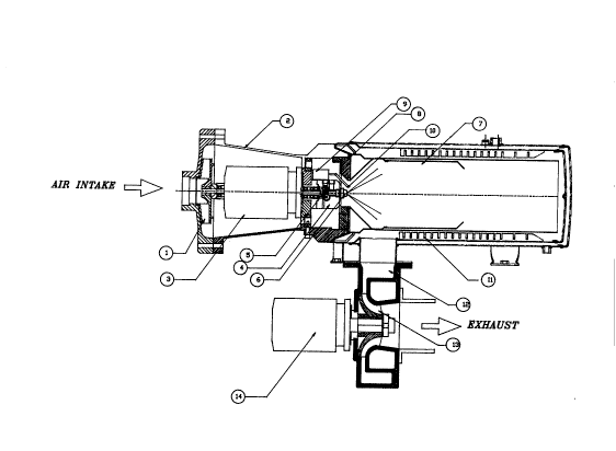

CLAIMS
1- A fuel powered furnace heater with an auxiliary power turbine
for automotive applications as shown in fig (1) where air enters at
the eye of the fan (1) air is pumped into the heater electric
chamber (2) by a blower fan (1) operated by an electric motor (3).
which drives a fuel module (4) containing a fuel pump (5) on which
discharge a nozzle (6) ensures atomization of the fuel into fine
particles inside the combustion tube (7) of the heater; designed so
that its entry a swirler (8) ensures appropriate rotation of the
air into a vortex thus ensures appropriate dispersion and mixing of
fuel with air; a mixture which is ignited by the ignition coil (9)

and the electrode(s) (10) of the heater; thus creating hot gases
from the combustion of the air-fuel mixture exchange their heat
with the engine water loop or with the cabin space heater via the
heat exchanger (11); and after passing through the heat exchanger,
the hot gases are directed into the volute (12) of a turbine (13)
for the generation of auxiliary power via a generator (14); which
in turn feeds back an electric current for the motor of the heater
(3), the battery of the vehicle, the water pump, or the blower of
the heat exchanger, or an air conditioning unit of the vehicle thus
making the furnace self powered and capable of operating
continuously without draining the energy of the battery.

Description

Note: Descriptions are shown in the official language in which they were submitted.


~ 156q~0

2 . O DESCRIPTION OF THE CONCEPT
20 In the last few years it has become recogni~ed that idling an
engine of a vehicle simply to produce heat was detriment to the
life of the engine and was a source of unwanted pollution. Small
mini-furnace have been developed to operate on the fuel of the
vehicle as a source of auxiliary heat for the engine block or the
25 cabin of tke vehicle . These furnaces eliminate the need to idle
the engines of the vehicle
Most mini-furnaces operate on the concept of using one or more
direct current motors to drive the blower, fuel pump and compressor
30 for adequate combustion of air and fuel. Electric power for these
rotating elements is drawn directly from the batteries of the
vehicle T~lis tends to drain the energy of the battery if the mini-
furnace is used extensively without turning the main engine on to
recharge the batteries once every few hours.
To remedy to this problem of draining the battery from its energy
the inventors came up with the concept of designing a special
turbine compartment on the exhaust of the furnace to regenerate
sufficient electricity for continuous operation. Such a turbine
40 would be coupled to a direct current generator . The electric
current thus generated may be delivered directly to the motors of
the heater or alternatively to the battery of the vehicle.
The energy that is available on the exhaust for the auxiliary power
45 turbine depend on the efficiency of conversion of heat from the
heat exchanger, and the amount of heat transfer, the efficiency of
combustion and the air/fuel ratio of the mixture. Typically the
energy required to drive th~ fan and pump is inferior to 5% of the
heat generated by combustion of the mixture. It is therefore
50 conceivable that sufficient waste heat would be available on the
exhaust to drive a turbine and a small generator as a feedback
current to the motor(s) of the fan, pump and compressor of the
heater.
_, _ _ _ _ _ _ . .. ... . .. . _ .. _ _ . ........ ... ...... . . . _ _ _

21~
Whereas the heat generated by heater is exchanged with the engine
block via a water loop, the generator of the turbine module must be
deslgned to supply sufficient electric current to operate the
heater and the water pump for the water loop
Whereas the heat generated by heater is ~x,changed with the vehicle
cabin or englne compartment via an air space heater, the generator
of the turbine module must be designed to supply sufficient
electric current to operate the heater and the blower for blowing
hot air into the cabin and engine compartmelrt.
Thus referring to fig(l) which shows an embodiment of the
invention . Starting at the eye of the fan ( 1 ) air is pumped into
the heater electric chamber ( 2 ) by a blower fan ( 1 ) operated by an
electric motor (3). The electric motor (3) drives a fuel module (4)
containing a fuel pump (5) . On the discharge of the fuel pump, a
nozzle (6) ensures atomization of the fuel into fine particles
inside the combustion tube ( 7 ) of the heater At the entry to the
combustion tube a swirler (8) ensures appropriate rotation of the
air into a vortex thus ensures appropriate dispersion and mixing of
fuel with air. The mixture is ignited by the i~nition coil (9) and
the electrode(s) (10) of the heater. The hot gases from the
combustion of the air-fuel mixture exchange their heat with the
engine water loop or with the cabin space heater via the heat
exchanger (11). At the exhaust from the heat exchanger, the hot air
is directed into the volute (12) of a turbine (13) for the
generation of auxiliary power via a generator (14).
Referring to fig (2) Auxiliary power from the generator (14) may be
connected back into the battery of the vehicle ( 15 ), the heater
motor (3), a water pump (16) for the engine block if the heater is
used to warm up the engine, or the blower (17) of a space heater if
the heater is used for production of cabin heat
During summer operation or during operation in areas of hot
climatic conditions, electricity from the auxiliary power unit may
be used to operate the air conditioning system of the vehicle
without turning on the main engine heater This approach requires
however that some of the heat of the heater be dumped into the
radiator of the engine where an electric fan achieves further
dissipation of heat to the environment.

Representative Drawing
A single figure which represents the drawing illustrating the invention.
Administrative Status

For a clearer understanding of the status of the application/patent presented on this page, the site Disclaimer , as well as the definitions for Patent , Administrative Status , Maintenance Fee  and Payment History  should be consulted.

Administrative Status

Title Date
Forecasted Issue Date Unavailable
(22) Filed 1995-08-25
(41) Open to Public Inspection 1997-02-26
Dead Application 1998-08-25

Abandonment History

Abandonment Date Reason Reinstatement Date
1997-08-25 FAILURE TO PAY APPLICATION MAINTENANCE FEE

Payment History

Fee Type Anniversary Year Due Date Amount Paid Paid Date
Application Fee $0.00 1995-08-25
Owners on Record

Note: Records showing the ownership history in alphabetical order.

Current Owners on Record
ABULNAGA, BAHA ELSAYED
RAAD, ELIE-JEAN
Past Owners on Record
None
Past Owners that do not appear in the "Owners on Record" listing will appear in other documentation within the application.
Documents

To view selected files, please enter reCAPTCHA code :


To view images, click a link in the Document Description column. To download the documents, select one or more checkboxes in the first column and then click the "Download Selected in PDF format (Zip Archive)" or the "Download Selected as Single PDF" button.

List of published and non-published patent-specific documents on the CPD .

If you have any difficulty accessing content, you can call the Client Service Centre at 1-866-997-1936 or send them an e-mail at CIPO Client Service Centre.


Document
Description 
Date
(yyyy-mm-dd) 
Number of pages   Size of Image (KB) 
Office Letter 1995-09-27 1 14
Abstract 1996-10-24 1 18
Description 1996-10-24 2 81
Claims 1996-10-24 2 32
Drawings 1996-10-24 2 49
Cover Page 1996-10-24 1 12
Representative Drawing 1997-08-07 1 18