Note: Descriptions are shown in the official language in which they were submitted.
2157I3S
p~Pa~UUT~ GROUND DISCONNECTING DEVICBS
l~NlCA~ FIELD
The present invention relates generally to
the field of parachute accessories, and more specifically
to improved devices which allow for the automatic release
of parachute borne loads upon contact with the ground.
P~-r~ ~D OF THE I~v~N~rION
In parachuting a load from an airplane it
is important that the load be safely secured to the
parachuting means during descent. Likewise, it is also
important for the load to be spontaneously released from
the parachuting means upon striking the ground, or other
supporting surface. Unless there is immediate separation
of the load from the parachuting means on ground contact
the load can be dragged over the supporting surface by
surface winds engaging the parachute.
Parachute ground disconnecting devices
have been developed which automatically release a payload
with ground contact. Such devices perform as coupling
means between the parachute and load to safely secure
loads when suspended during déscent of the parachute.
When the load makes contact with the ground so the load
weight falls the coupling device should automatically
open to allow separation of the load and parachute.
One significant problem associated with
parachute ground disconnecting devices heretofore has
been overcoming fluctuations in effective load weight
21~713S
during descent. ~or example, in the first few seconds
after parachute deployment, forces applied to
disconnecting devices can drop off severely or vary
significantly due to transient parachute inflation
phenomena. The device may repeatedly oscillate due to
snatch ~orces, parachute over-inflation and swing
through. To overcome such significant variations in
forces the release load percentage or l'RLP"~ which is the
ratio of the tension at the instant of disconnection to
the weight of the load during steady ~Ccent~ can be
lowered, e.g. below 25 percent. This however, can result
in the parachute ground disconnecting device not readily
releasing its load on ground contact, or exhibiting poor
high wind release characteristics. In fact, many earlier
parachute ground disconnecting devices required total
slack-off of tension when the cargo made ground contact.
But, with ground winds catching a parachute at the time
of desired disconnection there was usually no slack of
tension and the release device would not actuate. In
2~ attempting to modify ground disconnecting devices so the
weight required to initiate load disconnection is more
than zero and in some cases closer to the real weight of
the load, i.e. a RLP of >40 percent, trade-offs in
descent security can result which increase the potential
for premature delatching of the device and load losæ
while still airborne.
Hence, it has been observed that prior
efforts have not been entirely satisfactory in developing
parachute ground disconnecting devices capable of
providing both a high degree of load security at all
stages of descent and conditions while also providing the
desired instantaneous load release characteristics upon
ground contact, especially in the presence of high ground
winds and soft ~Lo~d conditions.
For instance, U.S. Pat. 2,732,245 appears
to disclose an automatic parachute release coupling
215713~
device which employs a time delay mech~n;sm, main canopy
activation and ground disconnecting action. However,
this earlier device relied on coil type springs
exclusively. It was found that with such linear type
springs constant RLPs were not readily achieved. As a
result, it was not possible to produce reliable load
disconnection on ground contact throughout the entire
rated load capacity of the device, under all wind and
ground conditions.
Other such devices have relied on load
suspending assemblies having components which were not
integral and capable of moving as fixed geometry units.
Consequently, if after parachute deployment load force
drops off or varies significantly, and erratic movements
occur there is increased risk of premature delatching
occurring. In addition, some earlier devices lacked the
desired high degree of reliability, especially during the
first few seconds after deployment before stable steady
descent occurs. During this stage of descent if the
disconnecting mech~nism is not isolated from other
component systems as to be rendered fully inoperative,
the risk of premature delatching can also be greater.
Earlier automatic parachute release
devices, such as those disclosed by U.S. 2,732,245, while
possessing merit, also relied on systems which added to
the t~chnical complexity and concomitant cost of the
devices, making them largely impractical and non-
economic, particularly those which were not readily
reusable.
Accordingly, it would be highly desirable
to have more reliable and reusable parachute ground
disconnecting devices which provide constant release load
ratios (as a percentage of suspended weight) over an
entire load range rating for a given device. Such
devices should be readily adaptable for a broad range of
payload sizes, including ultra-heavy payloads of up to 30
2157135
tons or more, such as required in parachuting armored
vehicles, and which have a high degree of reliability and
do not prematurely delatch while airborne, and
spontaneously separate from the parachute on ground
contact, even in the presence of high winds.
SUM~ARY OF THE INVENTION
Accordingly, it is a principal object of
the invention to pr~vide for improved parachute ground
disconnecting devices, especially those which are capable
of maintAining substantially constant RLPs. Generally,
devices of the invention are characterized by a casing
with at least one interior compartment, a load suspending
assembly located at a first end of the device and means
for connecting the device to a parachute located at a
second end of the device. Structurally, the devices also
consist of means for locking and releasing a load on the
load suspending assembly and spring means positioned in
the interior compartment of the casing. The spring means
are effective in ret~;ning the device in a retracted
position when not under load and limiting downward
deflection when under force of load. The devices also
have timer means for actuating the means for locking and
releasing a load on the load suspending assembly after
lapse of a sufficient time interval for stabilized
descent of the parachute and load, and for release of the
load from the load suspen~ing assembly as the spring
means returns towards a fully retracted position upon
ground contact by the load.
The spring means of the foregoing ground
disconnecting devices are characterized by non-linear
force displacement curves permitting load disconnection
to occur throughout the rated weight capacity of the
device when tension on the device falls to an adjustable
range generally from 25 to about 70 percent of the load
weight. Thus, the spring means can be comprised of a
2157135
plurality of disk type springs placed in stacks to
provide ever diminishing deflection with additional load
applied to the load suspending assembly.
It is a further object to provide ground
disconnecting devices wherein the means for locking and
releasing a load on the load suspending assembly
comprises a longitudinally movable bar or toothed rack
member which freely moves with fluctuating load weights
during the more turbulent initial period of descent, and
bar or rack locking means automatically actuated by the
~ timer means for engaging the movable bar or rack during
stabilized descent and which releases the load from the
load suspending assembly when the spring means returns
towards a fully retracted position with ground contact by
the load.
It is yet a further object to provide for
devices consisting of an upper casing with an interior
compartment and means for connecting with a parachute,
and an axially aligned load suspending assembly which is
2~ movable relative to the upper casing. The load
suspending assembly comprises a rod extending into the
casing interior, connecting means for holding a load,
means for locking and releasing a load from the
connecting means, and gear means, such as a rack for
engaging the locking and releasing means of the load
suspending assembly at a first end. The rack extends
into the upper casing interior at a second end.
Importantly, the device is powered by main spring means
providing restricted deflection. That is to say, the
main spring means is characterized as non-linear
(designed to a specific function) providing ever
diminishing deflection of the lower load suspending
assembly as additional load is applied. The main spring
means is positioned in the casing interior for engaging
with the rod of the load suspending assembly for
retaining the load suspending assembly in a retracted
21$713S
position prior to deployment, and for limiting the stroke
of the load suspending assembly away from the casing when
a load is applied. The device also includes timer means
for providing a delay interval corresponding
substantially to a period running from the time of
parachute opening to the time of stabilized descent.
Other elements of the device include rack locking means
automatically actuated by the timer means for engaging
the rack for preventing longitll~in~l movement of the rack
during stabilized descent, and when the distance between
upper casing and the lower load suspen~ing assembly moves
towards zero upon ground contact by the load, to delatch
the locking and releasing means for separating the load
from the parachute.
It is thus a principal object of the
invention to provide a reusable parachute ground
disconnecting device characterized by constant RLPs over
the entire rated load capacity, subiect to the constraint
of fixed latch geometry and associated fixed stroke to
reliably actuate load release with ground ~ontact. The
objectives of the invention are more readily achieved
thorough spring means characterized by non-linear force
displacement curves permitting load disconnection to
occur throughout the rated load capacity of the device
when tension on the device falls to about 25 to about 40
percent of the real load weight. Significantly, the
force of the load on the device need not drop to zero in
order to effectuate delatching. Within the above range
of 25 to 40 percent the risk of premature delatching or
resistance to load disconnection occurring on ~ uu~,d
contact is minimal. This is readily accomplished with a
plurality of disk type springs placed in varying stacks
for a shallow/short stroke of the load susp~n~;ng
assembly, even when under force of capacity loads. That
is to say, deflection of the load suspen~;ng assembly
from the upper casing is ever diminishing to a set final
215713~
--7--
deflection, i.e. disks flattened, as additional load is
applied.
It is still a further object of the
invention to provide a parachute ground disconnecting
device wherein the main spring means provides the energy
for retraction of the load suspending assembly towards
the upper casing on ~Loul,d contact for disengagement of a
lever mounted release arm to actuate delatching and load
release.
It is yet a further object of the
invention to provide timer means, such as in the form of
a gear train and escapement, and other timer types for
added security by providing automatic delays in actuating
gear or rack locking means for about an initial 5 to 20
second period in which the release mec~nism is isolated
from possible premature release at the transient period
of parachute deployment, and for readying the device for
automatic ground disconnect during steady, stable
descent.
It is still a further object of the
invention to provide a heavy duty version of the
parachute ground disconnecting devices having load
ratings of several tons for large loads, heavy equipment,
large personnel carriers, armored vehicles, and so on,
also characterized by substantially constant release load
percentages. The devices consist of an upper parachute
Ai~connecting block suitable for engaging several
parachutes and an axially aligned lower load susp~n~ing
casing having interior compartments and means for
connecting a load. The lower load susp~nAing casing is
movable relative to the upper parachute disconnecting
block, the latter comprising a plurality of rods
ext~nAing vertically downwardly into the interior of the
lower load suspenAing casing. The parachute disconnecting
block also includes an outer frame member for supporting
a plurality of parachute riser fingers and parachutes
2157135
when the fingers are locked, an axially slidable retainer
assembly (spring loaded) positioned adjacent to the outer
frame member for locking and releasing the parachute
riser fingers, and a gear, such as a rack for engaging
the slidable retainer assembly at a first end. The rack
extends into the interior of the lower load suspending
casing at a second end. Significantly, the device
includes non-linear main spring means to provide ever
diminishing deflection characteristics to the load
suspending casing with additional load applied. The main
spring means are positioned in the lower load suspending
casing for engaging with the rods of the parachute
disconnecting block for ret~in;ng the load suspending
casing in a retracted position when not under load, and
for limiting the stroke of the load susren~ing casing
away from the parachute disconnecting block when under
force of a load. The lower load suspending casing also
includes timer means for providing a delay interval
corresponding substantially to the period running from
the time of opening of a parachute to the time of
stabilized descent. Rack locking means are automatically
actuated by the timer means for engaging the rack and
preventing longitudinal movement of the rack during
stabilized descent. When the distance between the load
suspending casing and the parachute disconnecting block
moves towards zero upon ground contact the main spring
means retracts the axially slidable retainer assembly
against its spring loading to delatch the parachute riser
fingers and parachutes from the device. As with other
embodiments of the device, delatching is not dependent on
the load dropping to zero.
It is still a further object to provide an
even more simplified embodiment of the parachute ground
disconnecting device of this invention which still allows
for maintaining a substantially constant release load
percent, but where exact time delays for arriving at a
2157135
steady, stable descent are less critical. This further
embodiment consists of a casing with an interior
compartment and means for connecting with a parachute.
The device includes an axially aligned load suspending
assembly movable relative to the casing, a rod extending
into the casing interior, connecting means for holding a
load, and means for locking and releasing a load on the
connecting means with ground contact. The device employs
load release timer means and main spring means both
housed in the casing interior. The main spring means
engages with the rod for retaining the load suspending
assembly in a retracted position when not under load and
for limiting the stroke of the load suspending assembly
away from the casing when under force of a load. The
load release timer means includes a pushrod cylinder, an
axially aligned pushrod at a first end engaging the push
rod cylinder and linking with the locking and releasing
means of the load susp~nA;ng assembly at a second end.
Ram means are axially aligned with the pushrod cylinder
and pushrod. Importantly, the load release valve means
includes means for dampening vertical movement of the ram
means and pushrod when under compression, such as on
ground contact by the load.
It is still a further object to provide
for ground disconnecting devices with load release timer
means with dampening means for rams and adjacent pushrods
comprising a piston with an aperture for non-compressible
fluids for gradual displacement through the aperture over
a period of approximately 2 to about 20 seconds. The
device includes adjacent spring means positioned in the
pushrod cylinder for compression and gradual movement of
the ram means towards the pushrod and gradual
displacement of the hydraulic fluid when a load is
applied to the load sus~enAing assembly.
It is still a further object to provide a
parachute ground disconnecting device comprising a casing
2157135
--10--
with at least one interior compartment, means for
connecting the device to a parachute located at a first
end of the casing, a load suspending assembly having
latching means located at a second end of the casing,
means for locking and releasing a load on the load
suspending assembly including a longitudinally moveable
bar affixed to the means for connecting the device to a
parachute, and spring means positioned between the
longitudinally moveable bar and the load suspending
assembly. The spring means is characterized by limiting
the downward deflection of the casing from the
longitudinally moveable bar. The means for locking and
releasing a load on the load suspending assembly
comprises a longitll~inAlly moveable bar affixed to the
means for connecting the device to a parachute, axially
aligned means for engaging with the longitudinally
moveable bar and for releasing a load on the load
su6pending assembly on ground contact, means for
laterally deflecting the axially aligned means for
engaging with the longitudinally moveable bar and for
releasing a load on the load suspending assembly on
ground contact, and timer means for actuating the means
for laterally deflecting the axially aligned means for
engaging with the longitudinally moveable bar and for
releasing a load on the load suspending assembly. The
longitudinally moveable bar comprises a rack having a
plurality of adjacent teeth.
It is still a further object of the
invention to provide ground disconnecting devices wherein
the axially aligned means for engaging with the
longitudinally moveable bar and for releasing a load on
the load suspending assembly comprises a cup means, a
vertically rigid wire having one end engaged with the cup
means, and a vertically moveable pin means for contacting
and de-latching the latching means. The cup means is
adapted to engage with at least one of the teeth of the
2157135
rack.
It is still a further object of the
invention to provide ground disconnecting devices wherein
the means for laterally deflecting the axially aligned
means for engaging with the longitudinally moveable bar
and for releasing a load on the load suspending assembly
is a horizontally moveable bar spaced from the cup means.
The cup means is positioned on a vertical axis
sufficiently close to the horizontally moveable bar to
cause the cup means to disengage from the horizontally
moveable bar and return to axial alignment after the
vertically moveable pin means de-latches the latch on
ground contact.
BRIEF D~-~rDTPTION OF THE DRAWINGS
For a further understanding of the
invention, as well as its characterizing features
reference should now be made to the accompanying drawings
wherein:
FIG. 1 is a side elevational view of the
parachute ground disconnecting device in a non-loaded,
resting position with parts of the outer case removed to
show elements of the device;
FIG. 2 is a graph comparing RLPs of
parachute ~,ou-~d disconnecting devices equipped with
linear and non-linear type main springs for various load
sizes;
FIG. 3 is an enlarged plan view of the
timer employed in the parachute ground disconnecting
device of Fig.1;
FIG. 4 is an enlarged side view of the
running components of the timer taken along lines 4-4 of
Fig. 3;
FIG. 5 is a side elevational view of the
parachute ground disconnecting device under load with the
timer running during initial deployment of the device;
2157135
FIG. 6 is a side elevational view of the
parachute ground disconnecting device under load with the
rack in locked position during steady descent;
FIG. 7 is an enlarged fragmented view of
the rack teeth and rack locking means engaged therewith
in accordance with Fig. 6.
FIG. 8 is a side elevational view of the
parachute ground disconnecting device upon load contact
with the ground whereupon the device is unlocked and the
load released;
FIG. 9 is a side elevational view of an
alternative embodiment of the parachute ground
disconnecting device of the invention for large capacity
loads;
FIG. 10 is a view of the parachute riser
fingers in locked position taken along line 10-10 of Fig.
9;
FIG. 11 is a view of the parachute riser
fingers of Fig. 10 at the time of release and separation
of the parachutes;
FIG. 12 is a side elevational view of an
alternative embodiment of the parachute ground
disconnecting device of the invention.
Fig. 13 is a side elevational view of a
further embodiment of the parachute ground disconnecting
device of the invention.
Fig. 14 is an elevational end view of the
parachute ~L~U~Id disconnecting device of Fig. 13.
Fig. 15 is a side elevational view
opposite to that of Fig. 13.
Fig. 16 is a vertical section taken
generally along line 16-16 of Fig. 14.
Fig. 17 is an enlarged fragmentary view of
the rack and its companion pawl bell in a free position.
Fig. 18 is a fragmentary view, similar to
Fig. 17, of the rack and pawl bell with the pawl edge
215713S
-13-
engaged in the rack.
Fig. 19 is a horizontal cross sectional
view taken along line 19-19 of Fig. 17.
Fig. 20 is an enlarged fragmentary side
elevation similar to Fig. 15, with cover plate removed
and several areas broken away showing the timer output
pin contacting the pawl bell.
Fig. 21 is a view similar to Fig. 20
showing the timer output pin spaced from the pawl bell.0
n~crPTpTIoN OF THE ~h~u ~MBODIHENTS
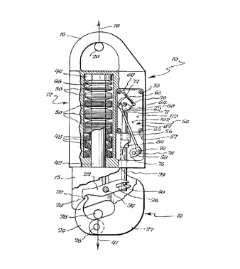
Turning to Fig. 1, there is shown a
preferred first embodiment of parachute ground
disconnecting device 10 in resting position before being
deployed. Device 10 may be used in supporting loads over
varying weight ranges from under 45 kg (100 pounds) and
up to several hundred kilograms. The capacity of a
typical disconnecting device could range, for example,
from about 34 kg (75 pounds) to about 227 kg (500
pounds). Larger capacity units for substantially heavier
loads will be discussed in detail below. All such
devices advantageously provide constant RLPs throughout
their rated load capacities.
Disconnecting device 10 includes principal
sections consisting of an upper casing or housing 12 and
a lower axially aligned load suspending assembly 14.
Integral with casing 12 is parachute connecting ring 16
for engaging with parachute 18, illustrated by a vertical
arrow only. Parachute riser finger 20 shown sectionally
may be affixed to the device via connecting ring 16.
Lower axially aligned load suspending
assembly 14 is shown by Fig. 1 in fully retracted
position butted against casing 12. Assembly 14 is
partially sheathed by outer protective housing 15. The
assembly consists of hook 22, release latch 24 pivotally
mounted to hook 22 through yoke and threaded pin assembly
2157I35
-14-
26, at one end, and locking edge 28 at a second end
interconnected with edge 30 of release arm 32, the latter
being rotatable through connecting pin 34. Release arm
32 includes slot 36 which slidably engages with pin 40 of
rack 39.
Spring means tnot shown) of conventional
design exerts force to maintain release arm 32 in a
locked position with release latch 24 prior to ground
contact by the load. This retains load ring 38 of
payload 41, shown only as an arrow, in a securely locked
mode on hook 22. While not shown in Fig. 1, when device
is first deployed lower suspending assembly 14
translates downwardly from upper casing 12, and during
the initial stages of ~Cc~nt rack 39 will be free to
translate and move downwardly and upwardly in step with
the lower suspending assembly without premature
delatching of the device.
The lower susr~n~ing assembly further
includes a rod 42 and nut 44 positioned for movement in
~0 cylinder 46 of the upper casing. As with rack 39,
downward movement of rod 42 and nut 44 occurs in concert
with a load suspended from hook 22 of the lower
suspending assembly. Cylinder 46 is preferably filled
with non-linear disk type springs 48 of conventional
design mounted on rod 42 for limiting free downward
movement of the assembly. More specifically, the
principal objective of the non-linear type springs is
ever diminishing deflection of the lower suspen~ing
assembly with additional load applied. As main springs
of the device, this can best be achieved by nesting disk
type springs into layered stacks 50 of varying numbers
for RLPs of 25 to 40 percent over the entire rated load
capacity for a given device. Various stacking patterns
may be used to achieve this end result. One includes
nesting several springs together into concave formats
wherein individual spring stacks are positioned in
2157135
alternative directions, i.e. front to back, and so on.
It was discovered, for example, when
spring stacks are layered in diminishing
numbers/thicknesses where the largest stacks are
positioned at the bottom of cylinder 46 and gradually
decrease in number towards the top of the cylinder near
nut 44 the desired ever diminishing additional deflection
characteristics of the load suspending assembly with
additional load applied occurs throughout the weight
capacity rating of the device. That is to say,
differential deflection will occur with a small load,
e.g., 34 kg (75 pounds) to produce downward movement,
e.g., 5 mm (0.20 inches) of the load suspen~ing assembly
from its resting point, whereas with a substantially
larger load, e.g. 227 kg (500 pounds), the relative
movement of the load suspending assembly will be, for
example, only 10 mm (0.40 inches), or in other words,
only 5 mm more for over 6.5 times more weight.
The significance of non-linear springs is
d~monstrated graphically by Fig. 2 and Tables I and II
below:
TABLE I - LINEAR SPRINGS
Example Starting Load (lbs) Release Load (lbs) RLP(%)
1 500 350 70
2 400 250 63
3 300 150 50
4 200 50 25
100 No Release
TABLE II - NON-TTN~P SPRINGS
1 500 155 31
2 400 130 32
3 300 100 33
4 200 65 33
100 25 25
2157135
Fig. 2 and Tables I-II demonstrate the
absence of a constant release load percentage within the
desired range of 25 to 40 percent of the starting/actual
load weight with a ground disconnecting device equipped
with linear springs, and constant RLPs with non-linear
main springs within the desired range of 25 to 40 percent
for all loads, regardless of weight.
In this manner, the ground disconnecting
devices of the present invention achieve constant RLPs
through non-linear springs to provide a load suspending
assembly with a downward stroke characterized by ever
diminishing deflection with additional load applied, in
combination with fixed latch geometry for constant load
release performance when the tension on the device falls
to about 25 to about 40 percent of the starting load
weight. Advantageously, the geometry of the
latching means does not change with variations in load
weight. Regardless of the particular value of gap "g"
attained during steady ~eCc~nt, a specific amount of gap
reduction, "~g", is required on ground contact for
release to occur. This is due to the fixed geometry of
release latch 24 and release arm 32. Through the use of
non-linear main spring stacks a condition is created
wherein the main spring force drops nominally to 30
percent of its initial value within the operating range
of the device with re-extension of the main spring by the
amount ~g. The limited deflection of the load suspending
assembly achieved with the non-linear springs even with
heavier loads restricts the degree of total movement of
the suspending assembly and ultimate movement of the
latch geometry to effectuate delatching and load release.
Hence, while greater weight will increase the deflection
of the suspending assembly away from the upper casing
somewhat, variations in load weight, and particularly
loads of greater weight do not necessitate modification
of the release latch geometry to effectuate reliable
2157135
-17-
delatching and load release over lighter weight loads.
Accordingly, constant RLPs are achieved within a desired
range of 25 to about 40 percent of the real load weight
to provide reliable delatching characteristics for all
loads within the rated capacity of a given device on
ground contact even in the presence of winds, all with
high descent security, i.e., virtually no risk of
premature delatching while airborne.
While the invention is specifically
demonstrated with disk type springs, it should be
understood that non-linear spring characteristics may
also be substantially duplicated with other types of
springs. For example, a short, rigid coil type spring in
combination with a governor, for example, for limiting
the downward stroke of rod 42 and nut 44, while less
preferred, may nevertheless be employed in place of
stacks of disk type springs.
In addition to cylinder compartment 46,
upper casing 12 has a second compartment 52 for housing
timer 54, pushrod 56, rack 39 and rack wedge 58. Timer
54 essentially functions as a "safety~' by providing an
initial delay period beginning with deployment of the
parachute when turbulence and fluctuating load weights
and movements present the greatest risks of premature
delatching and load loss occurring before ground contact.
During the initial 5 to 20 seconds after parachute
deployment before steady descent of the load occurs timer
54 provides an important interval prior to activation of
the ground disconnecting device by allowing unrestricted
movement of rack 39. By allowing such unrestricted
movement, momentary reductions in load weight due to
transient parachute inflation, etc., and resulting
retraction of the load suspending assembly by main spring
50 will prevent premature rotation of release arm 32 and
unlocking of release latch 24. Accordingly, timer 54
isolates the delatching system during the initial
2157135
-18-
transient period of parachute deployment until the load
achieves equilibrium and steady descent.
With lapsing of the time delay and with
steady descent of the parachute and airborne load,
locking of rack 39 with rack wedge 58 occurs preventing
further vertical movement of the rack. This effectively
activates the disconnecting device for delatching to
occur automatically upon ground contact as the weight
load on the device falls to about 25 to about 40 percent
of the starting weight.
Timer 54, which is mounted to the upper
casing in compartment 52 by threaded mounting screws 55,
includes a bellcrank 60 with locking ledge 62, cranking
input shaft 64, cranking spring 66 mounted to the timer
bearing plate 82 by pin 68 at a first end and to the
bellcrank by pin 70 at a second end. In running mode,
cranking spring 66 turns bellcrank 60 in a counter
clockwise direction. Fig. 1 is shown with the timer
wound for running by turning input shaft 64 clockwise
prior to the device being deployed. The uppermost end
of rack 39 includes a bellcrank lock 71 which rests
against bellcrank ledge 62 at the time of deployment.
Fig. 1 thus illustrates the configuration of the device
prior to deployment when not under load. A first end of
pushrod 56 is mounted for movement to bellcrank 60 with
linking pin 72. Pushrod 56 is also mounted for movement
at a second end to rack wedge 58 by linking pin 74. Rack
wedge 58, which includes a locking tooth 76, is mounted
for rotation to the upper casing 12 in compartment 52 by
connecting pin 78. Hence, counter clockwise movement of
bellcrank 60 produces a downward movement of push rod 56
and clockwise rotational movement of rack wedge 58, so as
to bring locking tooth 76 in an upward position towards
toothed rack collar 80.
Toothed rack collar 80 contains a
plurality of adjacent teeth. Rack 39 and toothed rack
2157135
--19--
collar 80 automatically index with movement of the load
suspe~ing assembly for engagement by locking tooth 76 of
rack wedge 58 between teeth of collar 80. The particular
teeth engaged with by locking tooth 76 is dependent on
the weight of the load. Accordingly, the parachute
ground disconnecting device provides the important
benefit of automatic sensing and registration of load
weight. Downward movement is determined by load weight.
With a fully inflated parachute, stable steady descent
and lapsing of the time delay rack 39, toothed collar 80
and lower suspending assembly 14 become locked against
any further sliding movement relative to upper casing 12.
Figs. 3-4 illustrate the internal
components of one representative embodiment of timer 54
which is a gear train and escapement type. The timer
consists of bearing plates 82, 84 with a plurality of
drilled bearing holes for gears and shafts. Spring 66
(Fig. 1) applies counter clockwise rotational forces to
bellcrank 60 and shaft 86 (Figs. 3-4). Rotation of bell
crank 60 turns gear 88 having 50 teeth with an 80 DP.
Gear 88 meshes with pinion 90 having 10 teeth with an 80
DP on shaft 92. Gear 94 contains 48 teeth with a 96 DP.
Rotation of gear 94 turns pinion 96 having 10 teeth with
a 96 DP on shaft 98. Gear 100 contains 44 teeth with a
96 DP. Rotation of gear 100 turns escapement pinion 102
having 10 teeth with a 96 DP on escapement shaft 104.
Escapement wheel 106 contains 24 teeth 60 sharp V form
having a root diameter 8.13 mm (0.320 inches) and an
outer diameter 10.62 mm (0.418 inches). Escapement wheel
106 mates with pallet 110. Revolution of escapement
wheel 106 on shaft 112 causes pallet 110 to oscillate
over a narrow angular range. Pallet 110 may have mass
addition (not shown) for increased energy dissipation and
reduced timer running speed.
Shafts 64, 86, 92, 98, 104 and 112 are
free to rotate in bearing openings in each of plates 82
`_ 2157135
-20-
and 84. Spring 66 rotates bellcrank 60 and shaft 86.
For every one rotation of shaft 86 there are 106
rotations of shaft 104 due to an increase in gear
staging. For every one rotation of shaft 104, pallet 110
goes through 24 full cycles of small angular oscillation,
coming to full stop twice per oscillation. Each time
pallet 110 is brought to a full stop, its kinetic energy
is dissipated in the form of acoustic emission, i.e. a
"click" and mech~nical vibration are generated.
Spring 66 imparts a certain amount of
energy to the timer system and pallet 110 dissipates this
energy. The speed of the timer is determined by the
speed producing an equilibrium between input spring
energy, which is relatively speed independent, and pallet
percussion energy out, which is very speed dependent.
The parameters which control the running speed consist of
spring force; overall gear ratio; pallet angular travel
from extreme to extreme, and moment of inertia of pallet
110 about the axis of shaft 112. In practice, the time
delay is determined by the speed at which bellcrank 60
travels and how far the bellcrank has to travel from the
point of release/ activation to the point of travel
completion.
In most instances, timer 54 is actuated
automatically. However, the timer can also be activated
semi-automatically whereby the timer is provided with a
pull pin (not shown) such that it can be rigged into the
overall parachute system for starting the timer running
when the parachute lines first reach their fully payed
out state.
While the invention has been illustrated
with timer means consisting of a gear train and
escapement type timer having running times of about 5 to
20 seconds, it should be understood that other timers may
be employed, e.g. pneumatic-time delay, and so on.
Operation of the parachute ground
~_ 215713~
-21-
disconnecting device may be demonstrated by reference to
Figs. S-8. Initial parachute deployment causes hook 22
of the load suspending assembly 14 to separate from upper
casing 12 by the distance "g" (Fig. 5). The downward
force 41 overcomes the retracting force of disk springs
48 in forming gap "g". This initial downward movement
causes bellcrank lock 71 on the end of rack 39 to
disengage from locking ledge 62 on bellcrank 60.
Bellcrank 60 begins to move counter clockwise under the
action of spring 66. The rotational movement is slow and
regular due to the damping imparted by gear train and
escapement type timer 54. Pushrod 56 interconnecting
bellcrank 60 and rack wedge 58 under counter clockwise
movement of the bellcrank produces a slow and regular
clockwise rotational movement of the rack wedge. Locking
tooth 76 moves towards toothed rack collar 80 as the rack
wedge rotates. So long as contact has not been made
between locking tooth 76 and any teeth of rack collar 80,
the lower suspending assembly 14, including rack 39,
release arm 32, release latch 24, hook 22 and rod 42 are
free to move together as a fixed geometry unit. If in
the first few seconds after parachute deployment force 41
drops off severely or varies significantly due to
transient parachute inflation the entire load suspenA i ng
assembly can freely retract back to the upper casing 12,
and translate away therefrom, repeatedly if nececc~r
without any premature delatching occurring.
Once stable, steady descent of the
airborne load has been achieved under a fully inflated
parachute, the gap "g" ~Fig. 6) between upper casing 12
and lower load suspending assembly 14 will settle to a
value which may be relatively large if load 41 is a heavy
payload, e.g. 227 kg t500 pounds), and relatively small
if load 41 is a lighter payload, e.g. 34 kg (75 pounds).
Locking tooth 76 on rack wedge 58 engages with toothed
collar 80 on rack 39 with lapsing of the time delay (Fig.
2157I3~
-22-
6). The rack becomes locked against any further vertical
movements relative to upper casing 12. Pushrod 56 is
preferably a compressible arm to assure that locking
tooth 76 on rack wedge 58 will be instantly driven and
seated between teeth on rack collar 80 under a sudden
upward movement of rack 39 (Fig. 7). The time delay for
this action to occur is achieved with timer 54, timed to
occur after the parachute is open and stable, based on
foreknowledge of how long parachute inflation and
stabilization is required in a worst case.
When payload 41 makes ground contact (Fig.
8), the force created by load 41 drops off suddenly
towards zero, and the gap "g" between upper casing 12 and
lower load suspending assembly 14 moves toward zero in
response thereto. Retraction of assembly 14 is driven by
the main spring action of layered non-linear spring
stacks 50. However, because rack 39 remains in a locked
condition it is not free to move upwardly with other
components of the load suspending assembly when the load
weight on the device moves towards zero. As a result of
pin 40 remaining stationary, release arm 32 mounted on
connecting pin 34 is forced downwardly in a clockwise
movement causing edge 30 to pivot upwardly from locking
edge 28 of the release latch 24 to instantaneously and
reliably delatch when load 41 drops to about 25 to 40
percent of its steady descent value. The ground
disconnecting device delatches without the load weight on
the device dropping to zero.
Figs. 9-11 relate to a further embodiment
of the parachute ground disconnecting device
incorporating the concepts of the invention for
maintaining a substantially constant release load
percent. This embodiment is especially adapted for
heavier loads, such as trucks, armored vehicles, and the
like, which may weigh from about 2,275 kg (5,000 pounds)
to about 27,000 kg (60,000 pounds), and more. The heavy
21571~S
-23-
duty ground disconnecting device consists of an upper
parachute disconnecting block 114, and an axially aligned
lower load suspending casing 116 which is movable
relative to the parachute disconnecting block. The
parachute disconnecting block consists of an outer
generally D-shaped frame 122 having dual spaced rods 118
and terminal nuts 119, each rod and nut extending
downwardly into cylindrically shaped interior spaces 120
in load suspending casing 116. The rods and nuts have a
plurality of non-linear spring stacks 124, such as disk
springs previously discussed. The stacks are preferably
of diminished size towards the lowermost end of cylinders
120. The spring configuration is characterized by a non-
linear force displacement permitting load disconnection
to occur throughout the rated weight capacity of the
device when tension on the device falls to about 25 to
about 40 percent of the real load weight upon ground
contact.
Outer frame 122 of the parachute
disconnecting block also includes a support bar 12~ for
holding multiple parachute riser fingers 128 as
connectors for parachutes 130 shown by arrows. Each
riser finger 128 and parachute can have a rated weight
capacity, for example, of 2273 kg (5,000 pounds). While
the device of Fig. 9 is illustrated with eight riser
fingers and parachutes for a total capacity of 18,182 kg
(40,000 pounds) this embodiment is intended to have up to
twelve or more such riser fingers for even larger
payloads.
Parachute disconnecting block 114 also
includes a vertically slidable riser finger retainer 132
(spring loaded into position) for locking and also
releasing the parachute riser fingers 128 when the
suspended load makes contact with the ~r oulld and the
weight of the load is reduced. The vertically slidable
retainer 132 includes a generally U-shaped slot 134
2157135
-24-
(shown best by Figs. 10-11) at the head of the retainer
for holding the fingers in a locked position around
su~o~L bar 126 of outer frame 122. Riser finger
retainer 132 includes parallel vertical rods 135, and
arms 136 mounted for rotation on their respective central
axes by pins 138, each vertical rod 135 having an arm 136
slidably mounted at a first end. The second ends of arms
136 are slidably mounted to the upper end 140 of rack
142. It will be understood the device includes spring
means (not shown) for maintAining riser finger retainer
132 in an elevated position wherein the riser fingers are
locked together around suppo.L bar 126 for securing the
parachutes.
Lower load susp~n~ing casing 116 consists
of load rings 144 for connecting payload 146, shown by
arrows; timer 148 with bellcrank 150 spring loaded for
counter clockwise rotation and bellcrank locking ledge
152; rotatable rack wedge 154 having locking tooth 156
for engaging toothed collar 158 mounted on rack 142.
Rack wedge 154 and bellcrank 150 are interconnected by
pushrod 160. Counter clockwise rotation of bellcrank 150
results in clockwise rotation of rack wedge 154 and
locking tooth 156 for engagement with teeth on toothed
collar 158 causing locking of rack 142 from vertical
movement after the airborne load has achieved steady
descent and the delay provided by timer 148 has lapsed.
Fig. 10 illustrates the locked position of
parachute riser fingers 128 during initial deployment and
steady descent of the load, prior to ground contact.
When the running timer becomes exhausted and rack 142
becomes locked, with ground contact of load 146 and the
weight of the load being reAllc~ main springs 124 retract
lower load suspending casing 116. Because rack 142 is
locked retraction of casing 116 results in rotational
movement of arms 136 and retraction of riser finger
retainer 132 (See Fig. 11) releasing riser fingers 128
21S7135
-25-
from U-shaped slot 134 to disengage the parachutes from
the device and payload.
Fig. 12 is a further embodiment of the
ground disconnecting device which provides the important
advantages of constant RLPs in the range of 25 to 40
percent of the real load weight. This alternative
embodiment, like those previously discussed, also
provides ever diminishing deflection of the lower
suspending assembly additional load applied using non-
linear springs and fixed latch geometry. The device ofFig. 12 is especially useful when specific time
delays are less critical beginning with the initial
transient period of parachute deployment to stable
descent occurs. The device offers the advantages of a
more simplified design, increased ruggedness, fewer
exterior seals, greater compactness and fully automatic
resetting, all without trade-offs in constant RLPs.
Instead of employing a timer with separate
gear train and escapement, bellcrank, pushrod, rack and
2G rack wedge for locking the rack after the initial
transient period of parachute deployment according to the
prior embodiments, the device of Fig. 12 utilizes a load
release timer 162, which serves an equivalent function of
the aforementioned elements. Load release timer 162,
which may include devices such as an hydraulic dash-pot,
is positioned in the interior of upper casing 164, and
consists of a guide gland or sleeve 166, and an upper
axially aligned liner 168. A vertically positioned
pushrod 170 is joined at a first end to release arm 172
of the lower suspending assembly 173 by means of pin 167
for movement in slot 176. Pushrod 170 at a second end is
threaded to pushrod cylinder 174 and is retained by means
of guide 171. Low drag wiper seal 175 is useful for
excluding foreign matter. Load release timer 162 also
utilizes a ram 178 axially aligned with pushrod 170. The
interior of pushrod cylinder 174 includes a spring 180
~ 2I571~
-26-
coiled around the lower portion of ram 178. Spring 180
is in contact with ram base 182 at a first end and flange
184 of pushrod cylinder 174 at a second end. Ram base
182 makes contact with pushrod head 183 when the device
is in locked position and not under load as illustrated
by Fig. 12. The upper end of ram 178 also includes a
piston 186 retained by nut 188. Piston 186 includes a
valve aperture 190 for transmission of a non-compressible
flui~ 192, such as hydraulic oil from the underside of
the piston to the upper side thereof when compressed
downwardly. Accordingly, valve aperture 190 is of
sufficient dimension to allow regulated leakage flow-
through of fluid 192 at a slow rate. Fluid 192 is
retained by seal 194 and O-ring 196.
Operation of the device of Fig. 12
includes the step of applying a load 198 to produce a
lowering of suspending assembly 173 from the upper casing
164 to produce a gap "g" (not shown). This also results
in a lowering of pushrod 170 and push rod cylinder 174
which also creates a gap between ram base 182 and pushrod
head 183. Because spring 180 is compressed by the
downward movement of pushrod cylinder 174 there is a
tendency of the gap between ram base 182 and pushrod head
183 to close in a slow regular manner, dampened by the
action of piston 186 which allows control of the rate of
downward movement by forcing hydraulic fluid 192 through
aperture 190.
If load 198 is relieved partially or
completely within, for instance, 0.25 second of initial
application, ram 178 will not have moved down
sufficiently to have any effect on pushrod 170 than to
cause a minor tremor in release arm 172. But, assuming
sufficient time has lapsed e.g. 2 to 20 seconds, after
deployment and steady descent occurs the gap between ram
base 182 and pushrod head 183 will close up completely.
When ground contact occurs the gap "g" (not shown)
2157135
-27-
between the suspending assembly 173 and the upper casing
164 rapidly closes as the force of load 198 on the device
drops. However, because ram 178 has been depressed
downwardly pushrod 170 is blocked from moving vertically
upwardly in a rapid manner on a time scale with ground
contact. This causes release of load 198 to occur due to
the "locked" state of pushrod 170 through clockwise
movement of release arm 172 and unlocking of release
latch 200.
After release of load 198, the gap "g"
between the upper casing 164 and lower suspending
assembly 173 becomes fully closed in the absence of a
load. Return spring means (not shown for clarity)
applies a firm counter clockwise torque to lever mounted
release arm 172. This torque is co~municated to pushrod
170 via pin 167 placing an upward thrust to the pushrod,
pushrod cylinder 174, ram 178 and piston 186, all of
which move upwardly in a slow and regular manner. After
several seconds, typically 10 to 30 seconds, release arm
172 has moved to reset position, and made ready for
reuse.
As with other embodiments of the
invention, the device of Fig. 12 exhibits a constant RLP
with load disconnection occurring throughout the rated
load capacity of the device when tension falls to about
25 to about 40 percent of the actual load weight.
Figs. 13-21 relate to a further embodiment
of the parachute ground disconnecting device. Figs. 13 -
show ground disconnecting device 300 having a
parachute attachment means 330 located at one end of
casing 302 for securing ground disconnecting device 300
to a parachute. At the other end of casing 302 is load
suspending assembly 308. Load suspending assembly 308
includes a latch 303 for securing a load to ground
disconnecting device 300.
Timer shaft 305 is provided with a slot
-28- 21 5 71 3~
329 at one end for winding the timer 310 (best shown in
Figs. 13 and 16). Slot 329 is engaged by a suitable flat
tool such as a screwdriver and wound in a clockwise
direction. As shown in Fig. 13 and 14, casing 302 has
raised bumps 306 to protect slot 329 from impact damage.
Raised bumps 306 also serve to provide tactile timing
reference marks for setting the time in low light
conditions. Slot 329 can be turned to align with raised
bumps 306 corresponding to the desired time setting. The
time can be set to any value between about 5 seconds and
about 20 seconds.
Fig. 15 shows a side elevational view of
ground disconnecting device 300 opposite to the view of
Fig. 13. Fig. 15 shows casing 302 including cover plate
375. Cover plate 375 allows access to the inner
components (not shown) of ground disconnecting device 300
for maintenance purposes, and is secured to casing 302 by
a plurality of screws 380.
Fig. 16 depicts a vertical section of
ground disconnecting device 300 taken generally along
line 16-16 of Fig. 14. The device is shown without a load
applied. Parachute attachment means 330 is affixed to
the upper end of rod 301. Parachute attachment means 330
may be affixed to rod 301 by a standard clevis and pin
arrangement. Rod nut 314 is affixed to the lower portion
of rod 301. In the no-load condition shown, rod nut 314
rests at its lower extreme position within casing 302.
Disk spring stack 313 is disposed between rod 301 and
casing 302. Disk spring stack 313 is preferably a non-
linear disk type spring which limits deflection of rod301 in relation to casing 302 when a load is applied to
ground disconnecting device 300.
Rod nut 314 acts on interrupter clip 312
to hold interrupter clip 312 in contact with escapement
311. As long as contact is maintained between
interrupter clip 312 and escapement 311, timer 310 cannot
` _ 2157135
-29-
run.
The lower portion of casing 302 includes
load suspending assembly 308. Load suspending assembly
308 is depicted in the latched position and includes
latch 303 and release arm 304. Spring and pin assembly
307 exerts force to maintain release arm 304 in the
latched position with latch 303 prior to ground contact
by the load.
When a load is applied to load suspending
assembly 308, casing 302 moves downward and rod 301 moves
upward out of casing 302, against the action of disk
spring stack 313. Rod nut 314 moves upward with rod 301.
Interrupter clip 312 is moved out of contact with
escapement 311 by the upward motion of rod nut 314
thereby allowing timer 310 to run. Preferably, the
distance rod nut 314 must move before interrupter clip
312 is moved out of contact with escapement 311 is a
fraction of the total upward distance rod nut 314 moves
under normal load conditions.
Timer 310 can be any conventional timer
means and may be similar to the timer means described in
connection with previously described embodiments of the
invention. Timer 310 includes timer output pin 320,
shown in greater detail in Figs. 20 and 21. Timer output
pin 320 moves toward pawl bell 321 under the action of
push rod 327. As timer 310 runs, link means 315 rotates
in a clockwise direction about timer shaft 305 causing
arm 326 to move push rod 327 in the direction of rod 301.
Timer output pin 320 is pivotally mounted on the lower
portion of push rod 327. As push rod 327 moves toward
rod 301, timer output pin 320 is moved laterally toward
pawl bell 321.
As shown in Figs. 16-18 the lower portion
of rod 301 is a rack 317 comprising a plurality of
grooves or teeth 340. When no load is applied to ground
disconnecting device 300 rack 317 resides within pawl
2157135
-30-
bell 321. Rack 317 is centrally suspended so as to be
freely vertically moveable within pawl bell 321 as long
as timer 310 is running. The maximum stroke of rack 317
under fluctuating load weight should not be so great as
to take rack 317 completely out of pawl bell 321. In
other words, one of the grooves or teeth 340 of rack 317
is always adjacent to pawl edge 325 regardless of the
weight of the load.
Fig. 17 shows the upper portion of pawl
bell 321. Pawl edge 325 is a sharp inward facing
machined edge which forms a circular pawl capable of
being positively engaged with any one of the teeth 340 of
rack 317. As previously stated, timer 310 advances timer
output pin 320 toward pawl bell 321 as timer 310 runs.
When timer 310 reaches the end of the set time, timer
output pin 320 pushes pawl bell 321 and pawl edge 325
into tight engagement with one of the teeth 340 of rack
317 as shown in Fig. 18. Once pawl bell 321 is engaged
with one of the teeth 340 of rack 317, pawl bell 321 will
move in synchronization with rack 317 and rod 301.
Fig. 19 is a horizontal cross sectional
view taken along line 19-19 of Fig. 17. Fig. 19 shows
rack 317 and teeth 340 centrally suspended within pawl
bell 321. Pawl edge 325 remains spaced at a slight
distance 342 from the outer circumference of teeth 340
while timer 310 is running.
In order for timer output 320 pin to push
pawl bell 321 into engagement with one of the teeth 340
of rack 317, timer output pin 320 must overcome the
resisting elastic cantilever force on pawl bell 321
exerted by music wire column 322, shown in Fig. 16.
Music wire column 322 is disposed within pawl bell 321
and maintains pawl bell 321 in axial alignment with rack
317 until timer output pin 320 laterally deflects pawl
bell 321.
Music wire column 322 is affixed at its
215713S
-31-
other end to cup pin 323. Because music wire column 322
is rigid in the vertical direction, cup pin 323 will move
vertically in synchronization with pawl bell 321. During
descent, spring 324 holds cup pin 323 in contact with cup
stop 319, and limits downward deflection of cup pin 323.
Cup stop 319 is permanently located within casing 302 by
dog grub screw 318.
Upon ground contact by a suspended load
(not shown), bullet nosed end 309 of cup pin 323 is
driven downward, causing release arm 304 to rotate
clockwise. Release arm 304 releases latch 303 after
slightly less that about 10 of clockwise rotation,
causing the desired release of the load from load
suspending assembly 308.
Pawl bell 321 and cup pin 323 sustain only
brief downward deflection before pawl edge 325 moves past
timer output pin 320. Once pawl bell 321 is free from
the laterally deflecting force of timer output pin 320,
pawl bell 321 returns to its axially aligned and centered
position underneath timer output pin 320. The distance
pawl bell 321 must travel to pass timer output pin 320 is
preferably just slightly more than neC~Rc~ry to reliably
delatch release arm 304 from latch 303. This prevents
jamming of ground disconnecting device 300 and allows the
device to be easily reset after having been operated
under heavy load conditions.
Preferably, Rod 301 is free to rotate
about the vertical axis. About 2 of rotational freedom
is desirable at the upper end of rod 301, where rod 301
is affixed to parachute attachment means 330. If the
upper end of rod 301 is held too rigid, the components of
~r oulld disconnecting device 300 may be damaged.
As with the previous embodiments the
device of Fig. 13 exhibits a constant RLP with load
disconnection occurring throughout the rated load
capacity of the device when tension falls to about 25 to
215713~
-32-
about 40 percent of the actual load weight.
While the invention has been described in
conjunction with various embodiments, they are
illustrative only. Accordingly, many alternatives,
modifications and variations will be apparent to persons
skilled in the art in light of the foregoing detailed
description, and it is therefore intended to embrace all
such alternatives and variations as to fall within the
spirit and broad scope of the appended claims.