Note: Descriptions are shown in the official language in which they were submitted.
~157179
IMPROVED SUBSTRATE CONFIGURATION
FOR CATALYTIC COMBUSTION SYSTEM
BACKGROUND OF THE lNV~NlION
Field of the Invention
The present invention relates to an apparatus and
process for the catalytically supported combustion of gas-
eous carbonaceous materials, including natural gas andmethane. In a more specific aspect, this invention re-
lates to an apparatus and process for catalytically sup-
ported combustion of natural gas or methane using a sup-
ported palladium oxide catalyst.
Description of Related Art
Catalytically supported combustion processes have
been described in the prior art, e.g., see U.S. Patent
3,928,961 to Pfefferle and U.S. Patents 4,065,917 and
4,019,316. The use of natural gas or methane in catalytic
combustion has been taught in the art, as has the use of a
palladium catalyst to promote such combustion oxidation.
See U.S. Patent 3,056,646 to Cohn, wherein the use of pal-
ladium catalyst to promote methane oxidation is disclosed,
as is an operable temperature range of 271C to 900C (see
column 2, lines 19-25).
U.S. Patent 4,154,568 to Kendall et al, dated May 15,
1979 discloses a catalyst bed design comprising a plural-
ity of carrier monoliths in the flow stream of the air/
fuel mixture, wherein the channel size in respective mono-
liths decreases progressively for monoliths at progres-
sively downstream positions, to provide substantially com-
plete combustion in the catalyst bed (see column 1, lines
47-59)
SUMMARY OF THE lNV~NlION
The present invention provides a combustor for cata-
lytically promoting thermal combustion of an inlet combus-
tion gas mixture flowed therethrough in a flow path which
21 ~71 7~
.. .
passes sequentially through a catalyst zone and then a
downstream zone of the combustor, there being a homoge-
neous reaction zone within the downstream zone. The com-
bustor comprises a catalyst body disposed in the catalyst
zone and comprising at least a first catalyst member and a
second catalyst member. The first catalyst member is com-
prised of a first carrier having a plurality of gas flow
channels extending therethrough and defined by channel
walls on which a first catalyst composition is carried.
The second catalyst member is disposed downstream of the
first catalyst member and is comprised of a second carrier
having a plurality of gas flow channels extending there-
through and defined by channel walls on which a second
catalyst composition is carried. The first carrier com-
prises a silica-magnesia-alumina material comprised pri-
marily of cordierite, mullite and corundum, and second
carrier comprises a ceramic fiber matrix material compris-
ing ceramic fibers. The composition of the ceramic of the
fibers comprises alumina, boron oxide and silica and the
ceramic fibers are fixed in a silicon carbide matrix.
The silica-magnesia-alumina material that comprises
for example, the first carrier, may comprise about 20 to
40 weight percent SiO2, about 3 to 6 weight percent MgO
and about 54 to 77 weight percent Al2O3, with from about
50 to 90 percent by weight of each of said SiO2, MgO and
Al2 03 comprising crystalline material, the balance com-
prising amorphous material. The crystalline material may
comprise about 15 to 40 percent by weight cordierite,
about 15 to 35 percent by weight corundum and about 10 to
30 percent by weight mullite, based on the weight of the
carrier.
The ceramic fiber of the ceramic fiber matrix materi-
al may comprise, for example, about 62 weight percent alu-
mina, 14 weight percent boron oxide and 24 weight percent
silica.
One aspect of the invention provides that the cata-
lyst member may comprise respective discrete bodies dis-
posed in proximity to each other, or in abutting contact
21 ~71 7
with each other.
According to another aspect of the invention, the
first catalyst composition may comprise palladium oxide
dispersed on a first refractory metal oxide support.
The first refractory metal oxide support may be sel-
ected from the group consisting of one or more of unim-
pregnated alumina, alumina impregnated with a rare earth
metal oxide, unimpregnated zirconia, zirconia impregnated
with a rare earth metal oxide, silica, titania, and a co-
formed rare earth metal oxide-zirconia. Similarly, the
second catalyst composition may comprise palladium oxide
dispersed on a second refractory metal oxide support which
may be the same or different from the first refractory
metal oxide support. For example, the first refractory
metal oxide support may comprise unimpregnated alnmi n~ and
the second refractory metal oxide support may comprise
alumina impregnated with a rare earth metal oxide. The
rare earth metal oxide may be selected from the group con-
sisting of lanthana, ceria, praseodymia and combinationsthereof. Alternatively, the first and second refractory
metal oxide supports may both comprise alumina impregnated
with a rare earth metal oxide.
Yet another embodiment of the invention provides that
the first catalyst composition may comprise palladium ox-
ide dispersed on a refractory metal oxide support and the
second catalyst composition may comprise a combination of
(i) the reaction product of palladium oxide and a metal
oxide selected from the group consisting of one or more of
samaria, lanthana and praseodymia admixed with (ii) a re-
fractory metal oxide binder.
Another aspect of the invention provides that the
combustor may comprise an intermediate catalyst member
disposed in the catalyst zone between the first catalyst
member and the second catalyst member. The intermediate
catalyst member comprises a carrier comprising the silica-
magnesia-alumina material and having a plurality of gas
flow channels therethrough and defined by channel walls on
which is disposed an intermediate catalyst composition.
21~7179
_ ~S7~79
The intermediate catalyst composition may comprise palla-
dium oxide dispersed on an intermediate refractory metal
oxide support. The intermediate refractory metal oxide
support may comprise alumina, which may optionally be im-
pregnated with a rare earth metal oxide, e.g., lanthana,
ceria, praseodymia or combinations thereof.
According to still another aspect of the invention,
the combustor may comprise a third catalyst member dispos-
ed in the catalyst zone downstream of the second catalystmember, and may comprise a carrier comprising the ceramic
fiber matrix material and having a plurality of gas flow
channels therethrough and defined by channel walls on
which is disposed a third catalyst material. The third
catalyst material may be selected from the group consist-
ing of (a) palladium oxide dispersed on a refractory metal
oxide support as described above and (b) a combination of
(i) the reaction product of palladium oxide and a metal
oxide selected from the group consisting of one or more of
samaria, lanthana and praseodymia admixed with (ii) a re-
fractory metal oxide binder. The binder may be selected
from the group consisting of one or more of silica, alu-
mina, titania and zirconia or alumina impregnated with a
rare earth metal oxide, or combinations thereof.
As used herein and in the claims, the terms "up-
stream" and "downstream" refer to the relative placement
of elements sensed in the direction of flow of the combus-
tion mixture through a catalyst apparatus according to the
inventlon.
BRIEF DESCRIPTION OF THE DRAWINGS
Figure 1 is a schematic plan view of a gas turbine
unit utilizing catalytic thermal combustors in accordance
with one aspect of the present invention;
Figure 2 is a schematic longitudinal cross-sectional
view of one of the catalytic thermal combustors of Figure
1 showing four cylindrical catalyst members arranged
therein;
Figure 2A is a view taken along line A-A of Figure 2
2~71 79
showing a cross section of catalyst member 1 of Figure 2;
Figure 2B is a view, greatly enlarged with respect to
Figure 2A, showing in cross section one of the gas flow
channels of catalyst member 1;
Figure 3A is a view similar to that of Figure 2 of a
catalyst bed according to the present invention comprising
a spacing member;
Figures 4A and 4B are scanning electron microscope
("SEM") photographs of cross sections of a fresh sample
and the aged catalyst member A3, respectively, of Example
1 (Piece 3 fresh (4A) and spent (4B) Run 58);
Figures 5A and 5B are SEM photographs of cross sec-
tions of a fresh sample and the aged catalyst member B3,
respectively, of Example 1 (Piece 3 fresh (5A) and spent
(5B) Run 60);
Figures 6A and 6B are SEM photographs of cross sec-
tions taken from the inlet and outlet ends, respëctively,
of spent catalyst member C3 of Example 2 (Run 63);
Figures 6C and 6D are SEM photographs of cross sec-
tions of spent catalyst member C4 and a fresh catalyst
member, respectively, of Example 2 (Run 63);
Figures 7A and 7B are SEM photographs of cross sec-
tions taken from catalyst members E3 and E4, respectively,
of Example 2 after aging; and
Figures 8A and 8B are SEM photographs of cross sec-
tions of the inlet and outlet ends, respectively, of cata-
lyst member F3 of Example 2, after aging.
DETATr~n DESCRIPTION OF THE lNV~.lION
AND SPECIFIC EMBODIMENTS lH~K~OF
Burning of carbonaceous fuels is associated with for-
mation of air pollutants, among the most troublesome of
which are nitrogen oxides (NOX). Nitrogen oxides. form
whenever air-supported combustion takes place at open-
flame temperatures. One approach to eliminating nitrogen
oxides involves catalytic post-treatment to reduce NOX to
nitrogen. A more economical method is to operate the com-
bustion process catalytically, at a temperature lower than
21 ~71 79
open-flame temperatures.
It has long been realized that little or no NOX is
formed in such a system. Typically, such catalytic com-
bustion of natural gas or methane, for example, utilizes apreburner or thermal combustor which employs flame combus-
tion to preheat combustion air to a temperature of 400C
or higher. Once the catalyst is sufficiently hot to sus-
tain catalysis, the preburner is shut down and all the
fuel and air are directed to the catalyst. Such a cata-
lytic combustor, if operated at temperatures below about
1300C to 1500C, avoids or at least controls to accept-
able levels the NOX formation which occurs at the higher
temperatures which are characteristic of the flame combus-
tion. However, such catalytic combustion which will func-
tion effectively at a high space velocity has heretofore
been generally regarded as commerically unattractive.
Reasons for this lack of commercial attractiveness include
the difficulty of economically combusting methane, the
principal component of natural gas, and the deactivation
and instability of the catalyst compositions employed, es-
pecially in the high-temperature end of the catalyst bed
where severe high temperatures may be reached. Because of
the susceptibility of the catalyst to such thermal deacti-
vation, many catalytic combustor designs are limited withrespect to the type and amount of fuel they can combust in
order to avoid deleterious high temperatures.
Conventionally, combustors comprise a catalyst zone
where heterogeneous combustion of the combustion mixture
is catalytically initiated, and a downstream zone where
homogeneous flame combustion occurs, supported by the
heterogeneous combustion reaction. A catalyst body is
disposed in the catalyst zone and comprises at least a
first catalyst member comprising a carrier coated with a
catalyst material. Generally, the catalyst material com-
prises a catalytically active metal, such as palladium ox-
ide, dispersed on a refractory metal oxide support mater-
ial. As will be illustrated below, the catalyst zone may
comprise additional catalyst members which may comprise
- 21S~1 79
catalyst materials which may be the same or different from
the first catalyst material. In such cases, the catalyst
members are sometimes collectively referred to herein as a
catalyst bed. The catalyst members are adapted to initi-
ate in the catalyst zone catalytically-supported, i.e.,
heterogeneous, combustion at the surfaces thereof and to
support thermal flame, i.e., homogeneous, temperature com-
bustion in the downstream zone, thus helping to avoid ex-
posing catalyst compositions to deactivating temperatures
and to limit the production of nitrogen oxides.
The carrier on which the catalyst composition is car-
ried is typically a monolith having a plurality of fine
gas flow passages extending therethrough, to provide a
honeycomb-type structure. The gas flow passages (some-
times referred to as "cells") in the honeycomb structure
are substantially parallel and defined by thin walls, and
may be of any desired cross section such as square, rect-
angular, triangular or hexagonal shape. The number of
channels per square inch of face surface, i.e., per cross-
sectional square inch (cpsi), may vary, depending upon the
particular application for which the catalyst bed is to be
used. Such honeycomb-type carriers are commercially
available having anywhere from about 9 to 600 or more
cpsi. The substrate or carrier monolith desirably is por-
ous and may (but need not) be relatively catalytically in-
ert to the combustion reaction as compared to the active
layers used in the invention.
The carrier should be refractory in nature, i.e.,
able to withstand thermal shock caused by the sudden in-
crease or decrease in temperature experienced at start-up
and shut-down of the combustor. The carrier should also
have good thermal strength so that it does not develop
structural flaws at the operating temperatures of the com-
bustor, i.e., temperatures as high as 1,500C. Conven-
tional cordierite monoliths such as those used to support
three-way catalysts for treating the exhaust gases of
automotive internal combustion engines are generally not
considered to be suitable in combustors of the present in-
~ - 21~1 79
vention because they can melt or otherwise fail at combus-
tor operating temperatures. Suitable carriers may com-
prise a combination of cordierite and other oxide materi-
als, e.g., a mixture of alumina, mullite and cordierite.Such carriers have physical properties more suited to com-
bustor operation than conventional ceramic substrates,
typically used to carry catalysts used in the treatment of
automotive exhaust gases, i.e., they exhibit better ther-
mal strength and thermal shock resistance, and are commer-
cially available, e.g., from the Dupont Company under the
designation PRD-66. An elemental analysis of this materi-
al provided by the Dupont Company describes the material
containing 70.4 weight percent Al~03, 24.9 weight percent
SiO2 and 4.2 weight percent MgO. However, another analy-
sis resulted in proportions of about 62.7 - 63.4 weight
percent Al2O3, 31.2 - 31.3 weight percent SiO2 and 5.4 -
5.7 weight percent MgO. Approximately 50 to 90 percent by
weight of each of the SiO2, MgO and Al2 03 may comprise
crystalline material, the balance comprising amorphous
material. Typically, the crystalline material comprises
15 to 40 percent cordierite, 15 to 35 percent corundum and
10 to 30 percent mullite by weight of the carrier. A more
detailed description of this material may be found in U.S.
Patent 5,079,064, the disclosure of which is hereby incor-
porated herein by reference thereto. Carriers comprising
such materials are sometimes referred to herein as Type I
carriers.
The Applicants have discovered a mode of failure of
catalyst members by physically examining the catalyst mem-
bers after they have been subjected to combustor operating
conditions. Specif ically, they have found that o~er the
course of prolonged use, some catalyst materials react
with the carrier on which they are coated. The reaction,
sometimes referred to herein as an interaction, has been
observed between catalyst materials comprising alnmi n~ and
Type I carriers and is believed to be caused by exposure
of the catalyst members to high temperatures, in a mechan-
ism involving steam present in the combustion gases. Al-
~- 21S71 Y9
though these catalyst members not only exhibit the primary
indication of failure, i.e., a significant reduction in
catalytic ability to initiate combustion, the observed
catalyst material/carrier interaction sometimes accomp~n-
ies a significant loss in the structural integrity of the
catalyst member as well as a loss of signficant quanti-
ties of catalytic metal from the catalyst material. These
effects tend to be most pronounced when the catalyst mem-
ber is placed at points more downstream within the cat-
alyst zone, since the combustion reaction progresses as
the combustion mixture flows downstream through the com-
bustor, establishing an increasing temperature gradient at
progressively downstream positions.
The Applicants have discovered a carrier monolith
that exhibits significantly less interaction with alll~inA-
containing catalyst materials than Type I carriers. Such
monoliths are available from the Minnesota Mining and Man-
ufacturing Co. (3M) under the trade designation "Siconex,"
and are described by the manufacturer as being formed from
a series of layers of woven alumina-boria-silica inorganic
fibers. The thus formed monoliths are then coate~ with
silicon carbide in a vapor deposition process which is be-
lieved to enclose the fibers in a silicon carbide matrix.
The silicon carbide matrix is believed to produce a silica
coating on the surface of the silicon carbide matrix when
the monolith is calcined. These monoliths have been found
to exhibit long-term thermal strength. The 3M Company
provided an assay of its Siconex monolith, which described
the monolith as comprising about 70% by weight silicon
carbide and about 30% by weight NEXTEL 312 ceramic fi-
ber. The NEXTEL ~ 312 ceramic fibers are described as
comprising an alumina-boria-silica material comprising 62
weight percent Al2O3, 14 weight percent B2O3 and 24 weight
percent SiO2. As will be illustrated below, Siconex-type
carriers have been found to resist deterioration due to
interaction with alumina-containing catalyst materials
disposed thereon. Such carriers are referred to herein as
Type II carriers to distinguish from more conventional
21~71 ~
--10--
carriers referred to as Type I carriers described below.
A combustor according to the present invention is
generally characterized in that at least one catalyst
member comprises a catalyst disposed on a Type II carrier.
Since the operating temperature in the combustor increases
at points progressively downstream in the combustor, it is
preferable to emplace catalyst members in the catalyst
zone in a sequence in which the catalyst members exhibit
increasing thermal stability at points increasingly down-
stream in the combustor. Accordingly, it is advantageous
to employ the Type II carrier in at least a relatively
downstream position in the catalyst bed. At more upstream
positions, less thermally resistant carriers may be em-
ployed, and may in fact be perferred if they provide su-
perior catalytic performance, as seen in Example 1 below.
It should be noted that a combustor according to the
present invention may find utility not only for combusting
methane or natural gas, but also for other fuels, e.g.,
number 2 fuel oil, jet fuel, normally liquid hydrocarbon
fuels, alcohols, e.g., methanol, oxygenated hydrocarbons
and even hydrogen, which may be reacted with carbon monox-
ide.
In addition to positioning carrier monoliths in cata-
lyst beds according to their thermal stabilities or cata-
lytic activities, the catalyst materials carried thereon
may also be chosen selectively. Co-pending, com~only as-
signed patent application Serial No. , filed on
addresses various catalyst materials and
their advantageous relative sequence in the catalyst bed,
and the disclosure of that application is hereby incorpor-
ated herein by reference. Briefly restated, the cited
patent application teaches that catalyst materials should
be disposed in relative upstream-downstream relation in
order of at least one of decreasing catalyst activity, in-
creasing thermal stability (i.e., escalating degradation
temperature) or escalating and preferably overlapping re-
generation temperature ranges.
Typically, catalyst materials for initiating the com-
21~717~
bustion of mixtures of carbonaceous fuels in air comprisea platinum group metal or oxide, such as palladium oxide,
dispersed on a support material comprising a relatively
inert refractory inorganic oxide such as alumina, which is
optionally impregnated with stabilizers, promoters or oth-
er additives. Other support materials such as silica, ti-
tania, umimpregnated zirconia, zirconia impregnated with a
rare earth metal oxide, ceria, co-formed rare earth metal
oxide-zirconia and combinations thereof may also be em-
ployed. The palladium oxide is dispersed on the support
material in a conventional manner, e.g., by impregnating
particles of the support material with a solution of a
soluble palladium compound and then calcining the impreg-
nated material. The support materials may be stabilizedagainst thermal degradation, e.g., by the impregnation of
stabilizing species, to provide a catalyst material better
suited for use at a relatively downstream position in the
catalyst zone. Alternative active components may be em-
ployed, such as binary oxides of palladium and rare earthmetals, which may be formed from the solid state reaction
products of palladium oxide and oxide of a rare earth
metal, such as samaria, lanthana, neodymia and/or praseo-
dymia. Typically, such binary oxides are combined with a
refractory metal oxide, such as alumina, to bind the ma-
terial to a carrier. These catalytic materials are des-
cribed in co-pending, commonly assigned U.S. Patent Ap-
plication Serial No. 07/684,409, filed April 12, 1991, and
commonly assigned U.S. Patent Application Serial No.
07/684,631, filed April 12, 1991, now U.S. Patent
5,102,639. The disclosures of aforesaid patent applica-
tion and issued patent are hereby incorporated herein by
reference. However, the sequence of catalyst materials in
a catalyst bed should not be viewed as a necessary limita-
tion for the present invention.
Catalyst failures may be alleviated in another re-
spect by providing a thermal buffer or separator body dis-
posed in a separator zone situated between the catalyst
zone where the catalyst body is disposed and the down-
21~71 7~
-
-12-
stream zone where high temperature homogeneous combustion
occurs. The separator body is described more fully in
co-pending, commonly assigned U.S. Patent Application
number , filed , 1993,
the disclosure of which is hereby incorporated herein by
reference. Briefly restated, the separator body prefer-
ably comprises a monolith similar in configuration to the
carriers on which catalyst material is deposited to form a
catalyst member, i.e., it may take the form of a honeycomb
monolith having a plurality of parallel gas flow passages
extending therethrough. The separator body is made of a
material that can withstand exposure to the high tempera-
tures produced by the homogeneous combustion that occurs
in a downstream zone of the combustor. Due to its place-
ment between the catalyst zone and the downstream zone
where homogeneous combustion occurs, the separator body
acts as an insulator to partially insulate the catalyst
body from the heat released by the homogeneous reaction.
Preferably, the separator body does not comprise cataly-
tically active materials. Thus, even when the downstream
portion of the combustor bed is exposed to temperatures
that would deactivate a catalytic material there need not
be an associated loss in combustion efficiency since the
catalyst bodies are shielded from such temperatures by the
separator body. In some embodiments, the separator body
may be disposed in close proximity to the catalyst member,
i.e., it is either disposed in abutting relation to the
catalyst body or is sufficiently close so that the chan-
neled flow of gases through the catalyst body is substan-
tially preserved as channeled flow through the sëparator
body.
Preferably, the first catalyst member, each optional
catalyst member and the separator body are discrete bodies
within the combustor. For example, the first catalyst
member will preferably comprise the first catalyst compo-
sition disposed on the first carrier and the second cata-
lyst member will likewise comprise the second catalyst
composition on a separate second carrier. Then, the first
2137l79
-
catalyst member and the second catalyst member may be dis-
posed within the combustor in adjacent, optionally abut-
ting, upstream/downstream relation to one another. The
catalyst members, thus disposed in proximity to each oth-
er, are preferably disposed with their respective gas flow
channels in mutual alignment. Thus, the flow of combus-
tion gases through the first catalyst member will be chan-
neled into the second catalyst member. If the two cata-
lyst members are not abutting, they should be in closeproximity, whereby the channeled gas flow is maintained
between them. Alternatively, the first catalyst member
the second catalyst member may be formed on a single, in-
tegral monolith by applying a coating of the first cata-
lyst composition on one end of the monolith and a coatingof the second catalyst composition on the other end of the
monolith. The separator body, which also comprises a re-
fractory body having a plurality of gas flow channels ex-
tending therethrough, may likewise be part of a single
monolith with the second or most downstream catalyst mem-
ber, with catalyst material being deposited on only one
end of the monolith to provide a catalyst member, and the
other end providing the separator body.
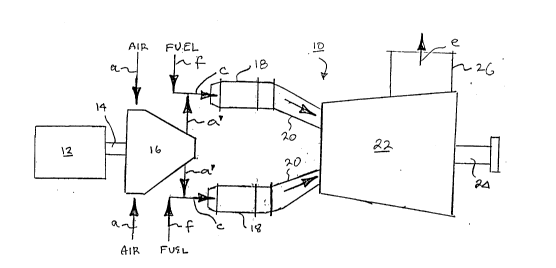
Referring now to Figure 1 there is shown in schematic
plan view a gas turbine 10 comprising a starter engine 12
connected by an engine shaft 14- to an air compressor 16,
which is provided with inlet air, via air inlet lines in-
dicated by arrows a, which is compressed by compressor 16
and discharged via lines a' into combustion gas inlet
lines c which are also supplied with a pressurized gaseous
fuel, such as natural gas or methane, via gas inlet lines
indicated by arrows f. The air and fuel combine to form a
combustion mixture which is introduced via lines c into a
plurality of catalytic thermal combustors 18, two of which
are illustrated in Figure 1 although it will be appreci-
ated that any suitable number may be employed. For exam-
ple, eight such combustors 18 may be utilized with their
outlets disposed equiradially about the inlet to the tur-
bine. Each catalytic thermal combustor 18 is provided
~7179
-14-
with an associated outlet duct 20 connected in gas flow
communication with a turbine 22 which may comprise a mul-
ti-staged turbine as well known to those skilled in the
S art. Turbine 22 is drivingly connected to a load coupling
shaft 24 to connect the turbine output to a suitable de-
vice, for example, an electric generator. The expended
combustion products are exhausted as shown by arrow e via
exhaust stack 26 for discharge to the atmosphere or for
further use or processing.
Figure 2 shows a schematic cross-sectional view of a
typical catalytic thermal combustor 18 comprising a canni-
ster 19 having an inlet section 28, a catalyst zone 30
comprising a catalyst body comprising catalyst members 1,
2, and 3, and a separator zone 31 including a separator
body 4 and a downstream zone 32. The three catalyst mem-
bers 1, 2, and 3, and separator body 4 are arranged in
abutting contact. That is, catalyst members 1 and 2 are
positioned in face-to-face abutting contact, as are cat-
alyst members 2 and 3. Catalyst member 3 and separatorbody 4 are also in abutting contact. Generally, the cata-
lyst members 1, 2, and 3 comprise a refractory carrier
substrate formed into what is sometimes referred to as a
monolithic or honeycomb substrate or carrier. The carrier
is a substantially cylindrical body (see Figure 2A) having
opposite end faces between which extend a plurality of
generally parallel, fine gas flow passages. Figure 2A
shows a typical catalyst member end face la of catalyst
member 1, schematically showing a plurality of fine, para-
llel gas flow passages extending longitudinally throughcatalyst member 1 to permit gas flow through catalyst
member 1. This construction is typical of all the cata-
lyst members 1 through 3 inclusively. The gas flow pas-
sages are defined by walls on which are disposed a coating
(often referred to as a "washcoat") of an active material
suitable to catalyze the oxidation of a gaseous fuel such
as natural gas or methane.
Figure 2B shows an enlarged view corresponding to
Figure 2A in which a typical gas flow passage 34 is shown
-15- 2 1 ~ 71 79
in cross-sectional view as being defined by four gas flow
passage walls 34a on which is coated a catalytic material
washcoat 36. The cross-sectional configuration of gas
flow passage 34 illustrated in Figure 2B is rectangular
but it will be appreciated that any suitable cross-sec-
tional configuration may be employed such as square, poly-
gonal, e.g., triangular, or circular. Further, the gas
flow passages may have a configuration attained by alter-
nating layers of flat and wave-form plates made of a suit-
able refractory material, as is well known to those skill-
ed in the art.
Preferably, separator body 4 is dimensioned and con-
figured to provide gas flow channels that correspond with
the channels in at least catalyst member 3, i.e., the cat-
alyst member against which the separator body is disposed.
This allows the gas stream to maintain channeled gas flow
from the catalyst member through the separator body.
According to another aspect of the invention, there
may be a spacing member 42 (Figure 3A) between catalyst
member 3 and separator body 4, to allow for improved in-
termingling of fuel and air before the combustion mixture
again flows over a catalyst member.
Example 1
Two catalyst beds designated Bed A (run 58) and Bed B
(run 60), each comprising four catalyst members designated
1-4 were prepared and arranged in a manner similar to the
three-catalyst member arrangement of the catalyst section
30 of cannister 19 illustrated in Figure 3A. The four
segments of each bed are designated Al, A2, A3 and A4, and
Bl, B2, B3 and B4, respectively. In both cases, the cata-
lyst member 1 (Al and B1) is positioned at the first ormost upstream position and the catalyst member 4 (A4 and
B4) is positioned at the last or most downstream position,
with catalyst members 2 (A2 and B2) and 3 (A3 and B3) in
the same order as illustrated in Figure 2. In Bed A, the
213~l79
-16-
carrier substrate for each catalyst member Al through A4
was a Type I substrate having 64 cells per square inch.
The substrate in catalyst member Al was coated with a cat-
alyst composition comprising palladium oxide dispersed onalumina, the washcoat containing 4% palladium by weight of
the washcoat, as palladium oxide, by impregnating the alu-
mina with a palladium nitrate solution and calcining the
impregnated alumina. Catalyst member A2 comprised a cata-
lyst material prepared by co-impregnating alumina with a
solution of cerium nitrate and palladium nitrate and then
calcining the impregnated alumina, to yield a material
comprising 8 weight percent palladium by weight of the
catalyst material as palladium oxide and ten weight per-
cent ceria by weight of the catalyst material. Catalystmembers A3 and A4 each comprised an active layer compris-
ing ~ catalyst composition prepared from a physical mix-
ture of alumina with the solid state reaction product of
lanthana and palladium oxide in a ratio of 2:1, respec-
tively, to produce a binary oxide of La4PdO7. The binaryoxide was produced by mixing an oxide of lanthana with
palladium oxide in selected weight ratios. The mixture is
mechanically ground to a size range of about 50 to 100 mi-
cron diameter particles. The grinding is followed by cal-
cination in air, for example, at a temperature of about1100C for about 66 hours, to provide a reaction mixture
containing the binary oxide of palladium and lanthanum.
Preferably, the lanthana and palladium oxide starting ma-
terials are mixed in stoichiometric proportions to produce
the desired compound. Thus, the molar ratio for the lan-
thana to PdO in the reaction mixture may be 2:1, 1:1 or
1:2. Although it is not necessary to use the starting ma-
terials in the molar ratios of the desired binary oxide
product, the use of such stoichiometric proportions has
been found to be advantageous, as described in aforesaid
U.S. patent application Serial No. 07/684,409. The binary
oxide comprised 7 weight percent of the catalytic materi-
al, the balance comprised alumina. Catalyst members Al,
A2 and A3 were disposed in abutting relation to each
2ls7l 79
other. The catalyst members A1 and A3 were 1.5" in
length; catalyst member A2 was 1" in length. Catalyst
member A4 was separated from catalyst member A3 by a spac-
ing member 1" in length. The spacing member was an annu-
lar body disposed about the periphery of catalyst members
A3 and A4, leaving the gas flow area between these cata-
lyst members unobstructed.
Catalyst bed B was prepared using the same active
layers on the catalyst member in the same order as de-
scribed for bed A, except that the palladium loading on
catalyst member Bl was 8% palladium, rather than 4% as in
catalyst member Al. Further, in catalyst bed B, all the
carrier monoliths were Type II substrates having 60 cells
per square inch instead of 64 cells per square inch.
Catalyst member B4 was separated from catalyst member B3
as was the case with catalyst members A3 and A4. The
configuration of beds A and B are summarized in TABLE IA.
TABLE IA
Catalyst Bed A
Catalyst Substrate
Member Type, Length Washcoat
A1 I 1.5" 4 wt.% Pd on alumina
A2 I 1" 8 wt.% Pd; 10% ceria/
alumina
A3 I 1.5" 7 wt.% 2La2O3.PdO/ 93%
alumina
A4 I 1.5" 7 wt.% 2La2O3.PdO/ 93%
alumina
21 ~ ~1 79
-18-
TABLE IA (CONTINUED)
Catalyst Bed B
Catalyst Substrate
5 MemberType, Length Washcoat
Bl II 1.5" 8 wt.% Pd on alumina
B2 II 1" 8 wt.% Pd; 10% ceria/
alumina
B3 II 1.5" 7 wt.% 2La2O3.PdO/ 93%
alumina
B4 II 1.5" 7 wt.% 2La2O3.PdO/ 93%
alumina
To compare the efficacy of the catalyst beds in
igniting combustion, they were placed in a combustor
through which an air/fuel mixture comprising methane in
air was introduced at fixed velocities as set forth in
TABLE IB below. The temperature of the inlet stream was
increased until complete combustion of the fuel was at-
tained, this temperature being reported as the ignition
temperature. Combustion was sustained for a duration of
some hours as shown in TABLE IB, and the inlet temperature
was then reduced until combustion was extinguished, and
the extinction temperature was noted. In some instances,
the fuel content of the combustion mixture was reduced as
well. The results are set forth below in TABLE IB.
TABLE IB
Bed Fuel~) Inletb) Ign.C) Timed)
A Content Vel. Temp(C) (hrs.) Extinction
Run 1 4% 30ft/s 455 2 445
35 Run 2 4% 30ft/s 490 6.5 435
Run 3 3.9% 30ft/s 490 2.5 496(3.6% CH4)
Run 4 4% 30ft/s 570 3 582(3.5% CH4)
`- 21 5 71 79
--19--
TABLE IB (CO,.l lN U ~ )
Bed Fuel~) Inletb~ Ign.C) Timed)
B Content Vel. Temp(C) (hrs.) Extinction
Run 1 4% 30ft/s 512 4 452-480
Run 2 3.45% 30ft/s bed did not initiate complete
combustion at 590
Run 3 4% 50ft/s bed could not initiate
complete combustion
~) Volume percent of methane in air.
b ) Linear velocity in feet per second of combustion
gas at entry to catalyst beds.
c) Ignition temperature in C.
d ) Duration of combustion in hours.
~) Temperature in C at which combustion was extin-
guished.
The data in TABLE IB show that catalyst bed A exhib-
ited greater catalytic activity than catalyst bed B, as
reflected by the generally lower ignition temperatures of
catalyst bed A and the difficulty displayed in initiating
combustion over bed B. This is surprising in view of the
greater quantity of palladium oxide applied to segment Bl
as compared to segment A1.
1. Bulk Assay Results
The catalyst material on catalyst members A4 and B4
were assayed for palladium and lanthanum content and the
results of the respective assays were compared to those
for fresh samples. The catalyst material disposed on cat-
alyst member A4 (comprising a Type I substrate) showed aloss of 85.5% of palladium content from the catalyst coat-
ing, but no loss of lanthanum. The catalyst material on
catalyst member B4 (comprising a Type II substrate) showed
no loss of either catalytic metal.
- -
21~71 79
-20-
2. SEM Microprobe/Mapping Results
Sections of spent catalyst members A3 and B3 were ex-
amined by scanning electron microscope, as were samples of
identical fresh catalyst members for comparison. The re-
sults were produced in the form of electron micrographs,
i.e., "SEM photographs", which were visually examined for
evidence of substrate or catalyst deterioration. The SEM
photograph for catalyst member A3 (comprising a Type I
substrate) is shown on the attached Figure 4B next to that
of the fresh catalyst on a Type I substrate shown in Fig-
ure 4A. It is clear from Figure 4B that the Type I sub-
strate suffered a deterioration in the constituent fibers
during the activity test. In addition, it appears that
the catalyst washcoat was interacting with the substrate,
as evidenced by the apparent movement of the washcoat/sub-
strate interface toward the center of the substrate struc-
ture. Finally, a microprobe was used to determine the
presence of palladium in the fresh and spent samples. No
palladium was detected in the spent sample.
In SEM photographs of samples taken from the fresh
and spent catalyst members B3 (comprising Type II sub-
strates), Figures 5A and 5B, no loss of substrate appears
to have occurred during the activity test; palladium was
detected in both samples and there does not appear to be
significant detrimental interaction between the catalyst
material and the Type II substrate.
The foregoing data indicate that the catalyst mater-
ial disposed on a Type II substrate employed in the down-
stream portion (catalyst members 3 and 4 in Figure 2) of acatalyst bed exhibits less deterioration of the catalyst
carrier, and less loss of catalytic material from the
washcoat. However, the initial overall catalytic activity
of a catalyst bed such as bed B comprising only Type II
substrates is not as high as that of a catalyst bed (Bed
A) comprising only Type I substrates.
- 21~7~ 7~
-21-
Example 2
To determine whether the relatively high catalytic
activity of catalyst disposed on Type I substrates and the
resistance to thermal degradation of catalyst members hav-
ing Type II substrates could be effectively combined, four
additional catalyst beds designated bed C, bed D, bed E
and bed F were prepared, each comprising 2 or 3 catalyst
members prepared as described above in Example I, and a
separator body. TABLE IIA summarizes the configurations
of the four catalyst beds.
TABLE IIA
Catalyst Bed C (Comparative)
Catalyst Substrate
Member Type, Length Washcoat
C1 I 1.5" 8 wt.~ Pd on alnm;n~
C2 I 1" 8 wt.% Pd; 10% ceria/
alumina
C3 I 1.5~ 7 wt.% 2La2O3.PdO/93%
alumina
C4 I 1.5" alumina
Catalyst Bed D (Comparative)
Catalyst Substrate
Member Type, Length Washcoat
D1 Same as C1 Same as C1
D2 Same as C2 Same as C2
D3 I 1.5" alumina
D4 I 1.5" alumina
2l~7l 79
-22-
TABLE IIA (CO~11NU~)
Catalyst Bed E
5Catalyst Substrate
Member Type, Length Washcoat
El Same as C1 Same as Cl
E2 Same as C2 Same as C2
E3 II 1.5" alumina
E4 II 1.5" alumina
Catalyst Bed F
15 Catalyst Substrate
Member Type, Length Washcoat
Fl Same as C1 Same as C1
F2 Same as C2 Same as C2
F3 II 1.5" 7 wt.% 2La2O3.PdO/ 93%
alumina
F4 II 1. 5" alumina
All the Type I substrates in catalyst beds C, D, E
and F had 64 cells per square inch, and all the Type II
substrates had 60 cells per square inch. The washcoat
loadings on the catalyst members of beds C, D, E and F was
1.5 g/in3.
The efficacy of each catalyst bed C, D, E and F was
tested by placing the beds in a combustor to determine
their respective initiation temperatures for a 4% methane
in air combustion mixture. Two evaluations were performed
for beds C and E, and three evaluations were made for
catalyst beds D and F. The results are set forth below in
TABLE IIB.
- 2~71 ~9
-23-
TABLE IIB
Ignition Conditions
Cat. Inlet Init. Vel. Fuel Conc. Extinction
Bed Temp.(oC) (ft/s) Vol. (%) Temp.(oC)/Fuel %
C 480-500 50 4.0462-480 / 4.0
420 30 4.0
D 487-550 50 4.1-3.75
530 60 4.0496 / 4.0
485-495 30 4.0465-485 / 4.0
E 512 60 4.0506 / 4.0
550-578 50 4.0515-520 / 4.0
F 475 60 4.0452 / 4.0
504-545 50 4.0487-515 / 4.0
472-477 30 4.0440 / 4.0
The data of TABLE IIB show that catalyst beds E and F
according to preferred embodiments of the present inven-
tion provide catalytic activity comparable to that of ca-
talyst beds C and D which do not comprise Type II sub-
strates in the downstream catalyst members, i.e., which
comprise Type I catalyst beds throughout. This is sur-
prising, in view of the higher catalytic activity attained
by Type I catalyst members as compared to Type II catalyst
members, as demonstrated above.
The foregoing catalyst beds C, D, E and F were aged
by placing them in a combustor and passing a combustion
mixture comprising 4% methane in air at an inlet linear
velocity of 30 to 60 feet per second to initiate combus-
tion for a period of 4 to 20 hours. Segments C3, C4, D3
and D4 all had visually discernable structural cracks, but
segments E3, E4, F3 and F4 appeared to be intact. There-
after, samples of the spent catalyst members were examined
by scanning electron microscope and compared against fresh
( unaged) samples for visual evidence of deterioration. In
some cases, samples were taken from both the inlet end and
the outlet end of a particular catalyst member.
Figure 6A and Figure 6B are SEM photographs of a
cross section of spent catalyst member C3 taken at the in-
2ls7l 79
-24-
let and outlet ends, respectively, and clearly reveal that
the outlet end of catalyst member C3 suffered greater de-
terioration than the inlet end. Figure 6C is a SEM photo-
graph of a cross section of the spent catalyst member C4showing evidence of deterioration and catalyst-substrate
interaction with the Type I substrate therein. Figure 6D
is a view similar to Figure 6C of a fresh, i.e., unused,
catalyst member of the same composition. Energy Disper-
sion Spectroscopy ("EDS") showed a loss of palladium onthe catalyst material of catalyst member C3. Figures 6A-
6D thus confirm that Type I substrates disposed in the
downstream portion of the catalyst bed interact under op-
erating conditions with the active layer thereon with a
tendency toward greater interaction at more downstream po-
s ltions .
Figures 7A and 7B are SEM photographs of cross sec-
tions of catalyst members E3 and E4 showing little deteri-
oration and catalyst material-substrate interaction. Fig-
ures 8A and 8B are SEM photographs of cross sections ofthe inlet and outlet ends of catalyst member F3 showing no
loss of palladium at either end. Thus, Figures 7A, 7B, 8A
and 8B confirm the resistance of Type II substrates to
detrimental interaction with the active layer thereon
under conditions which would result in degradation of Type
I substrates.
Although it is believed that the catalyst material on
members C3 and F3 degraded during their respective combus-
tor runs, and thus became catalytically inactive, it was
apparent that member F3 retained more palladium than did
member C3, as would be expected in view of the bulk assay
results of Example 1. Therefore, in the event that the
upstream catalyst members failed and the catalyst beds
cool sufficiently to allow the catalyst material on mem-
bers C3 or F3 to regenerate, it is likely that bed F wouldshow better performance after regeneration than bed C, due
to the greater quantity of palladium retained in segment
F3.
-
~ 21 3 71 79
-25-
While the invention has been described with reference
to particular embodiments thereof, it will be appreciated
that numerous variations to the described embodiments will
be within the scope of the appended claims.