Language selection

Search

Patent 2157511 Summary

Third-party information liability

Some of the information on this Web page has been provided by external sources. The Government of Canada is not responsible for the accuracy, reliability or currency of the information supplied by external sources. Users wishing to rely upon this information should consult directly with the source of the information. Content provided by external sources is not subject to official languages, privacy and accessibility requirements.

Claims and Abstract availability

Any discrepancies in the text and image of the Claims and Abstract are due to differing posting times. Text of the Claims and Abstract are posted:

  • At the time the application is open to public inspection;
  • At the time of issue of the patent (grant).
(12) Patent: (11) CA 2157511
(54) English Title: HEATING APPARATUS
(54) French Title: DISPOSITIF DE CHAUFFAGE POUR QUEUES DE PLAQUE
Status: Deemed expired
Bibliographic Data
(51) International Patent Classification (IPC):
  • H01M 10/14 (2006.01)
  • H01M 50/541 (2021.01)
  • H01M 2/28 (2006.01)
(72) Inventors :
  • HOPWOOD, ROBERT TIMOTHY (United Kingdom)
(73) Owners :
  • TBS ENGINEERING LIMITED (United Kingdom)
(71) Applicants :
  • TBS ENGINEERING LIMITED (United Kingdom)
(74) Agent: OSLER, HOSKIN & HARCOURT LLP
(74) Associate agent:
(45) Issued: 2005-07-26
(86) PCT Filing Date: 1995-02-16
(87) Open to Public Inspection: 1995-08-24
Examination requested: 2001-09-14
Availability of licence: N/A
(25) Language of filing: English

Patent Cooperation Treaty (PCT): Yes
(86) PCT Filing Number: PCT/GB1995/000323
(87) International Publication Number: WO1995/022845
(85) National Entry: 1995-09-01

(30) Application Priority Data:
Application No. Country/Territory Date
9403164.8 United Kingdom 1994-02-18

Abstracts

English Abstract


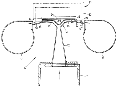
This invention relates to apparatus for heating the
lugs of battery plates. The apparatus 10 includes a hot
air duct 11 which communicates with a nozzle 12 having a
head 13 that defines a pair of opposite facing nozzles 14.
Each nozzle 14 has an outlet 15 from which extends a
generally flat and divergent plate 16, The plate 16
entrains hot air passing through the outlet 15 into a
generally flat stream so that the hot air impinges on lugs
19, but not of the rest of the group 18 of plates and
separators.


French Abstract

L'invention se rapporte à un dispositif destiné à chauffer les queues des plaques d'un accumulateur. Ce dispositif (10) comprend un conduit d'air chaud (11) communicant avec une buse (12) dotée d'une tête (13) définissant une paire de buses (14) opposées. Chaque buse (14) est dotée d'un orifice de sortie (15) duquel s'étend une plaque (16) généralement plate et divergente. Cette plaque (16) entraîne l'air chaud passant par l'orifice de sortie (15) sous forme de courant généralement plat, de manière que cet air chaud entre en contact avec lesdites queues (19), mais pas avec le reste du groupe (18) de plaques ni avec les séparateurs.

Claims

Note: Claims are shown in the official language in which they were submitted.


5


THE EMBODIMENTS OF THE INVENTION IN WHICH AN EXCLUSIVE
PROPERTY OR PRIVILEGE IS CLAIMED ARE DEFINED AS FOLLOWS:

1. Apparatus for heating a lug of a battery plate includ-
ing means for defining a treatment position for the plate
with its lug projecting into a lug position, a nozzle
connectable to a source of hot gas and having an outlet
directed at the lug position, and means defining a surface
extending from the outlet and diverging from a direction
of the outlet away from the treatment position whereby hot
gas passing through the nozzle will be entrained into a gas
stream passing through the lug position and along the
surface.

2. Apparatus as claimed in, Claim 1, wherein the surface
defining means comprise a generally flat plate.

3. Apparatus as claimed in Claim 1 or Claim 2, wherein
there is a step between the outlet and surface to define
partially the lug position.

4. Apparatus as claimed in any one of Claims 1 to 3, for
heating lugs on battery plates with intervening separators
arranged in a group, wherein the outlet and surface extend
substantially along the width of the group.

5. Apparatus as claimed in Claim 4, having a pair of
nozzle and surface defining assemblies; one for each set of
lugs on the groups.

6. Apparatus as claimed in Claim 4 or Claim 5, wherein the
treatment position defining. means includes a guard for
preventing contact between the groups and the nozzle.

7. Apparatus as claimed in Claim 6, wherein the guard is
formed by a plate having openings through which lugs can


6


project.

8. Apparatus as claimed in any one of Claims 1 to 7,
wherein the nozzle outlet has a height of between 1mm to
3mm.

9. Apparatus as claimed in claim 8, wherein the nozzle
outlet has a height of 2mm.

Description

Note: Descriptions are shown in the official language in which they were submitted.


~~~7~II
1
Heating Apparatus
This invention relates to apparatus for heating the
lugs of battery plates and in particular, but not
exclusively, to apparatus for carrying out this heating step
when the plates are arranged in groups prior to having
straps cast on them.
It is known that, particularly when certain fluxes are
used, the porosity of the joint between a battery lug and
its cast-on strap can be considerably reduced if the
temperature of the lug is raised significantly and preferab-
ly to over 150°C. The heating normally takes place using
hot air and the air temperature is typically 350°-400°C.
For the most part this method has been limited to certain
specialised batteries, such as computer stand-by batteries,
because the hot air from the nozzle tends to degrade the
separators which are used between the plates in most common
form of batteries, e.g. automotive or truck batteries.
Where the separators are individual sheets between the
plates at least one manufacturer has attempted to push
physically the separators away from the hot air stream but
without any significant success. Such an approach is in
any case impractical when, as is quite common, the separ-
ators are in the form of an envelope in which the battery
plates sit.
From one aspect the invention consists in apparatus for
heating a lug of a battery plate, including means for
defining a treatment position for the plate with its lug


2~ ~7~1I
2
projecting into a lug position, a nozzle connectable to a
source of hot gas and having an outlet directed at the lug
position, and means defining a surface extending from the
outlet and diverging from the direction of the outlet away
from the treatment position where hot gas passing through
the nozzle will been trained into a gas stream passing
through the lug position and along the surface.
In a preferred embodiment the surface defining means
comprise a generally flat plate and it is particularly
preferred that there is a step between the outlet and the
surface to define partially the lug position.
In most cases it will be convenient to use the appar-
atus with an assembled group of plates and separators in
which case the outlet and the surface may .extend at least
substantially along the width of the group. There may be a
pair of oppositely facing nozzles and surface defining
assemblies; one for each set of lugs on the group.
The treatment position defining means may include a
guard for preventing contact between the groups and the
nozzle, in which case the lugs may project through openings
in the guard.
Although the invention has been defined above, it is to
be understood that it includes any inventive combination of
the features set out above or in the following description.
The invention may be performed in various ways and a
specific embodiment will now be described, by way of
example, with reference to the accompanying drawing, which
is a schematic cross-sectional view of a double nozzle with


3
battery group shown in outline.
Lug heating apparatus is generally indicated at 10 and
includes a hot air duct 11 which communicates with a nozzle
12 having a head 13 generally in the form of a pair of
wings. Each wing 14 defines a nozzle outlet 15 from which
extends a generally flat and divergent plate 16, which
extends to the inlet of an exhaust duct 17.
As can be seen in the Figure, when an inverted and
gripped battery group 18 is positioned over the nozzle 12
its lugs 19 lie immediately adjacent respective outlets 15
of the head 13. The hot air passing out of the outlet 15
heats the lugs 19 to the desired temperature.
However, in the absence of the plates 16 the hot air
would extend in a diverging stream which would impinge on
the separators 20 and, if they are in envelope form,
actually enter inside the envelopes 20. This would cause
immediate degradation of the separator material and almost
inevitably lead to short-circuits within the battery.
Surprisingly this substantial problem is solved by the
presence of plates 16 which have the effect of entraining
the air into a stream which passes essentially along the
surface 21 of the plates 16 so that only the lugs 19 are
heated. This effect can be enhanced by a step 22 being
provided between the outlet 15 and the surface 21 which
enables the lug to be inserted firmly into this stream.
The exact mechanism for creating the stream is not
known for certain, but it is believed that when air exits
the nozzle and impinges on the plate it is guided into a


~I~~~1~
4
fast flowing layer which results in a localised low pressure
region which then entrains the rest of the hot air, increas-
ing the effect, and the layer is essentially held there by
the surrounding atmospheric pressure. This simple but very
surprising solution enables a very precisely controlled air
stream to be created at whatever location is required for a
particular plate geometry. It has been determined that if
the nozzle outlet is too high, the air stream becomes too
broad for it to be effectively entrained, but the actual
dimension depends on the air velocities and temperatures
being used. Simple experiment will determine the appropri-
ate dimension, but for the Applicants' set-up nozzle outlet
heights of between lmm - 3mm are acceptable and 2mm is
particularly preferred.
It will be appreciated that the upper surface 23 of the
head 13 is extremely hot and if the separators are not
trimmed accurately there is a danger that they might impinge
on that head. For this reason a spring-loaded plate 24 can
be provided to act as a guard to prevent such contact taking
place. The plate will be formed to allow the lugs 19 to
project beyond it.
In certain uses at least, it may be desirable to
achieve close temperature control on a nozzle-by-nozzle
basis. In that case cold air may be blown into a manifold
containing individual heaters for each nozzle and the
manifold may be connected by individual tubes passing
through the duct 11 which then simply acts as a support.

Representative Drawing
A single figure which represents the drawing illustrating the invention.
Administrative Status

For a clearer understanding of the status of the application/patent presented on this page, the site Disclaimer , as well as the definitions for Patent , Administrative Status , Maintenance Fee  and Payment History  should be consulted.

Administrative Status

Title Date
Forecasted Issue Date 2005-07-26
(86) PCT Filing Date 1995-02-16
(87) PCT Publication Date 1995-08-24
(85) National Entry 1995-09-01
Examination Requested 2001-09-14
(45) Issued 2005-07-26
Deemed Expired 2011-02-16

Abandonment History

There is no abandonment history.

Payment History

Fee Type Anniversary Year Due Date Amount Paid Paid Date
Application Fee $0.00 1995-09-01
Registration of a document - section 124 $0.00 1995-11-23
Maintenance Fee - Application - New Act 2 1997-02-17 $100.00 1997-01-30
Maintenance Fee - Application - New Act 3 1998-02-16 $100.00 1998-02-12
Maintenance Fee - Application - New Act 4 1999-02-16 $100.00 1999-02-10
Maintenance Fee - Application - New Act 5 2000-02-16 $150.00 2000-02-10
Maintenance Fee - Application - New Act 6 2001-02-16 $150.00 2001-02-13
Request for Examination $400.00 2001-09-14
Maintenance Fee - Application - New Act 7 2002-02-18 $150.00 2002-02-05
Maintenance Fee - Application - New Act 8 2003-02-17 $150.00 2003-02-05
Maintenance Fee - Application - New Act 9 2004-02-16 $200.00 2004-01-30
Maintenance Fee - Application - New Act 10 2005-02-16 $250.00 2005-02-08
Final Fee $300.00 2005-05-13
Maintenance Fee - Patent - New Act 11 2006-02-16 $250.00 2006-01-30
Maintenance Fee - Patent - New Act 12 2007-02-16 $250.00 2007-01-30
Maintenance Fee - Patent - New Act 13 2008-02-18 $250.00 2008-01-30
Maintenance Fee - Patent - New Act 14 2009-02-16 $450.00 2009-02-17
Owners on Record

Note: Records showing the ownership history in alphabetical order.

Current Owners on Record
TBS ENGINEERING LIMITED
Past Owners on Record
HOPWOOD, ROBERT TIMOTHY
Past Owners that do not appear in the "Owners on Record" listing will appear in other documentation within the application.
Documents

To view selected files, please enter reCAPTCHA code :


To view images, click a link in the Document Description column. To download the documents, select one or more checkboxes in the first column and then click the "Download Selected in PDF format (Zip Archive)" or the "Download Selected as Single PDF" button.

List of published and non-published patent-specific documents on the CPD .

If you have any difficulty accessing content, you can call the Client Service Centre at 1-866-997-1936 or send them an e-mail at CIPO Client Service Centre.


Document
Description 
Date
(yyyy-mm-dd) 
Number of pages   Size of Image (KB) 
Representative Drawing 1999-06-01 1 18
Cover Page 1996-02-05 1 16
Abstract 1995-08-24 1 16
Representative Drawing 2005-02-28 1 10
Description 1995-08-24 4 162
Claims 1995-08-24 2 52
Drawings 1995-08-24 1 21
Claims 2004-05-20 2 48
Claims 2004-12-10 2 49
Abstract 2005-07-11 1 16
Cover Page 2005-07-14 1 39
Fees 2004-01-30 1 43
Fees 2002-02-05 1 54
Assignment 1995-09-01 8 348
PCT 1995-09-01 20 1,169
Prosecution-Amendment 2001-09-14 1 68
Prosecution-Amendment 2001-12-10 1 46
Fees 2003-02-05 1 43
Prosecution-Amendment 2003-11-25 2 47
Fees 1998-02-12 1 53
Fees 2001-02-13 1 56
Fees 1999-02-10 1 73
Prosecution-Amendment 2004-05-20 4 88
Fees 2000-02-10 1 53
Prosecution-Amendment 2004-07-07 2 40
Prosecution-Amendment 2004-12-10 4 98
Fees 2005-02-08 1 41
Correspondence 2005-05-13 1 42
Fees 1997-01-30 1 156