Note: Descriptions are shown in the official language in which they were submitted.
215775~
SCOPE OF THE INVENTION
The present invention relates to an imaging
system for creating digital images of very faint or low
light specimens. More particularly the imaging system
includes an image intensifier coupled to an integrating
cooled charge coupled device (CCD) camera, and in which the
output of the intensifier is integrated onto the CCD camera
for relatively long periods of time.
BACKGROUND OF THE INVENTION
Standard solid state and tube-type cameras are
excellent for imaging well-illuminated biological
specimens. However, standard cameras lack the sensitivity
to image specimens under low light conditions, as for
example, those which result in an irradiance of less than
about 20 picowatts/cm2 at 500 nm. By way of comparison of
the sensitivity desired, the detection limit for the human
eye is about 17 picowatts/cm2 (10-3 foot candles) at 500
nm.
Traditionally, low light specimens are imaged by
one of three approaches, intensification, integration or
photon counting.
Intensification, as for example, is disclosed in
U.S. Patent No. 5,204,533 to Simonet, involves the coupling
of an image intensifier to a CCD camera. The image
intensifier typically includes a photocathode, a phosphor
screen and a multichannel plate lMCP) connected between the
photocathode and phosphor screen and provides an enhanced
image of a specimen. Amplification factors of up to about
90,000 are possible with this type of device.
In the image intensified CCD camera, the image is
created at three or four planes. At each of these planes,
there is some loss of quantum efficiency. Therefore, the
21~77 `~
-
-- 2
image intensifier is operated at high gain to overcome
signal losses within the optical chain. High gain shortens
intensifier life, and increases noise. At very high gain
factors, noise and ionic feedback through the MCP become so
severe that further improvement of sensitivity is
impossible. Even when run at maximum gain, conventional
image intensified CCD cameras are not sensitive enough to
image the dimmest specimens.
Faced with a typical very dim specimen, most
image intensified CCD cameras will fail to produce an
image, or will produce a very poor image, in which the
target will be difficult to discriminate from background,
and the image will not reflect the true range of target
intensities. In the worst cases, the target will be
indiscriminable from background.
Conventional image intensified CCD cameras use
short integration periods and, in most cases, the
integration period is equal to a single television frame.
The short integration period allows the intensifier to be
used with standard, low-cost video cameras, as for example,
are used in the television industry. In other cases, the
intensifier is gated, to use very short integration periods
(e.g. 1 msec). The use of gating allows the intensifier to
be used with specimens that would be too bright for a
standard intensifier, and can also be used to run the
intensifier in a photon counting mode.
It is possible to construct image intensified CCD
cameras with higher sensitivity, as for example, to
increase the gain of MCPs by mounting two or more MCPs in
serial fashion. This can result in much higher levels of
gain, though linearity of response and dynamic range are
compromised. In addition, multi-stage MCPs add greatly to
the cost of a device. Other than very costly and
- 21577~
-
- 3 -
specialized multistage cameras, there are no image
intensified CCDs that can image very dim specimens.
While all cameras perform some integration in
that they operate by accumulating light over a period of
time, integrating cameras generally refer to cameras which
integrate for periods of longer than a video frame (i.e. 33
msec.) In this regard, most intensified CCD cameras
operate at video frame rates and would not be considered to
include integration capabilities.
U.S. Patent No. 4,922,092 to Rushbrooke et al.
discloses the use of an image intensified CCD camera which
is coupled to a special fibre optic lens. The fibre optic
lens provides an efficient light pipe between spatially
invariant specimens and the input of the intensifier.
While Rushbrooke suggests the use of integration on a CCD
camera for periods of up to one second, it is disclosed as
being preferable that the image be read out at television
frame rates. This short integration period might be
sufficient for some specimens connected via the efficient
light pipe, however, the short integration period does not
provide sufficient sensitivity to allow imaging of
spatially variable specimens.
Conventional integrating cameras have a broader
dynamic range (up to four orders of magnitude vs. 1.5 for
an image intensified CCD), higher quantum efficiency (40%
is typical) and better contrast transfer than image
intensified CCDs. However, they require more photons to
overcome noise inherent to the camera.
In addition, while the invention disclosed by
Rushbrooke may be suitable for biochemical specimens in
well plates, it would be, however, incapable of imaging
most biological specimens. In particular, biological
21~7~
specimens are spatially variable, and cannot be coupled to
the intensifier by a light pipe. Instead, they must be
imaged using a lens. The use of a lens is less efficient
than a light pipe, and lens-based cameras present special
difficulties in that they require much higher sensitivity
than the light pipe cameras disclosed in Rushbrooke.
A photon-counting camera uses a selected image
intensifier operating at very high levels of gain. The
intensifier transforms incident photons on the input window
into somewhat diffused spots of light on the output window.
The spots of light from the intensifier which are bright
enough to be detected by a low-lag video camera form the
basis of photon-counting imaging. Sensitivity can be high
enough to detect single photons, but without processing of
the spots of light, resolution is poor because of the
diffusion inherent to the amplification process.
Resolution recovery circuitry (a digital
discriminator in the video camera or an imaging system)
selects the brightest part and/or center of gravity of the
light spot, to remove some of the diffusion and regenerate
some of the resolution lost by the amplification process.
Now, the incident light is present as a spatially localized
event within a frame buffer. It is this resolution
recovery which is a critical aspect of the photon counting
camera. The camera is exposed to the specimen until enough
counts are accumulated to form a usable image. In a sense,
the photon counting camera uses both intensification and
integration. However, in photon counting mode, the
integration is quantal. Suprathreshold scintillations are
detected as counts assigned to a specific XY location
within the image. The camera sensor is periodically
sampled for the presence of detected events (at rapid
rates, e.g. 1 millisecond). There is no image integration
in the camera sensor, before readout, but rather, image
- 21577S~
integration occurs within a memory buffer as sequential
readouts are summed.
In practice, the photon counting camera has two
disadvantages. It requires longer exposures than the
present invention. It also forms images with poor spatial
resolution. However, it does have much broader dynamic
range, because counts can be accumulated over long periods
of time without saturating the detector. Photon counting
cameras are best suited to imaging the very dimmest
specimens when broad dynamic range is more important than
image quality and speed. Their major disadvantages are
high cost, and that they produce images with relatively
poor resolution. The present invention is best suited to
imaging somewhat less dim specimens, when reasonable cost,
superior image quality, and speed of operation are more
important than dynamic range.
SUMMARY OF THE INVENTION
Accordingly, it is an objective of the present
invention to provide a system for use in imaging very
low-light specimens using intensification in combination
with extended periods of integration, lasting from one or
more seconds to one minute or more.
Another object of the invention is to provide an
apparatus which can image very dim specimens, and which may
be built at a relatively low cost.
A further-object of the invention is to provide
an electronic camera having a very high level of
sensitivity which is readily adaptable for imaging a
variety of different samples, and without the need of
physically coupling the sample to a fixed sample holder.
- 21 ~'155
-- 6
Another object of the invention is to provide a
highly sensitive imaging apparatus which includes an
integrating CCD camera for recording the image, and which
is adapted to perform integration within the camera sensor
and before readout.
A further object of the invention is to provide
an imaging system particularly suited for imaging low-light
biological specimens which may be spatially variable.
Another object of the invention is to provide a
camera for imaging very faint specimens which can be used
in either integration or photon counting mode.
To achieve at least some of the foregoing objects
the present invention provides a camera which has an
enhanced level of sensitivity by using a synergistic
combination of image intensification and integration. The
applicant has appreciated that by coupling the output of an
image intensifier to an integrating camera capable of long
periods of integration the disadvantages of prior art low
light imaging cameras may be overcome. Instead of running
the intensifier at very high gain, or using multi-stage
intensifiers, the intensifier may thereby be operated at
optimal gain levels and accumulate its output over
relatively long periods of time. The integration time
period might be from a few seconds to minutes. As any
integration period may be selected, even very faint
specimens can be seen, without excessive intensifier gain.
With the present invention, high sensitivity is
achieved by engineering the camera to use long integration
periods. For example, the present invention can image a
typical chemiluminescent southern blot in about 10 seconds
using an fl.2 lens. By way of comparison, the same
specimen would typically require about a 3 minute exposure
~77S5
-- 7
with a cooled CCD camera, a two minute exposure on film,
and would be invisible to a standard image intensified CCD
camera.
In the integrating camera, the signal is
accumulated onto a CCD sensor for a period of time. Both
video integrating cameras and asynchronous integrating
cameras may be used with the present invention. Video
integrating cameras accumulate signal over a number of
video frames, directly onto the CCD element and before the
camera is read out into a frame buffer. That is, one might
integrate two or more video frame (each being 1/30 sec),
before an image is output from the camera. Asynchronous
integrating cameras integrate and read out in the same way
as video integrating cameras, but do not have fixed frame
rates. They can accumulate an image onto the chip over any
time period. Integration periods might be 100 msec, or any
other time interval.
A preferred embodiment of the imaging system may
be obtained by the use of long-term integration of the
output of an image intensifier onto a cooled CCD camera.
With such a system components may be selected at reasonable
cost to provide a system having low noise, flat field
response, and high inherent contrast, which does not
require direct coupling to specimens (is lens-based), and
which can be used to image a broad variety of specimens
over a very broad range of specimen intensities. At the
user's option, frame averaging can be added to reduce
noise, and shading correction can be added to remove
background inhomogeneities.
The imaging system therefore is provided with an
image intensifier placed in front of a CCD camera. The
image intensifier has relatively low quantum efficiency
(typically less than 20~), but can provide very high levels
- 21~77~i5
-- 8
of gain. The intensifier may be coupled to the CCD camera
by a relay lens, or alternatively, by a fibre optic
coupling. A relay lens allows the intensifier to be used
with any camera, is not subject to the "chicken wire"
pattern that tends to appear in fibre optic images. In
addition, a relay lens will not delaminate as fibre optic
couplers tend to. Fibre optic couplers are advantageous as
they transfer light more efficiently than relay lens
couplers, and allow the intensifier to be used at lower
gain.
of the intensifier, three major types (i.e. GEN
I (generation 1), GEN II (generation 2), and GEN III
(generation 3)) are in common use, each differing in
component organization and in the materials from which the
components are constructed. Most preferably an Extended
Blue GEN III image intensifier is used fibre optically
coupled to the CCD camera. The applicant has discovered
that the intensified camera unit of the present invention
is well-suited to imaging dim specimens. When used at
video frame rates, this intensifier has a detection limit
of about 4 x 10⁻⁷ foot candles. Used within the present
invention, the intensifier becomes much more sensitive.
The synergistic combination of integration and
intensification of the present system provides several
advantages over integration alone. First, images can be
formed in a much shorter time period. An exposure of 10
seconds with the present invention is roughly equivalent to
an exposure of 3 to 4 minutes with a thermionically cooled
integrating camera, and 1 to 2 minutes with a cryogenically
cooled camera. Second, the present invention can be lower
in cost than a high-quality cooled integrating camera.
In use of the integrating camera, the signal is
accumulated onto a CCD sensor or element for a period of
2157755
time lasting for two or more seconds up to several minutes.
Both video integrating cameras and asynchronous integrating
cameras may be used with the present invention. Video
integrating cameras accumulate the signal over a number of
video frames, directly onto the CCD element and before the
camera is read out into a frame buffer.
In biological research, cooled integrating
cameras may be used if exposure time, convenience, and cost
are not major factors. Preferably the integrating camera
of the present invention incorporates a cooling element to
maintain the CCD element at a cooler temperature and permit
integration over a longer period of time.
A liquid, cryogenically or thermionically cooled
camera, such as one incorporating a Peltier cooler element
has, for example, been found to be suited for use with the
present invention. In contrast to the 18 bit precision of
cryogenically cooled camera, liquid or thermionically
cooled cameras typically function to only 12 or 14 bit
precision, are not as sensitive as cryogenic cameras, and
need rather long exposures (typically 2 to 10 minutes) to
image dim fluorescence, chemiluminescence or
bioluminescence. One must sit with the imaging system
while it exposes, and any number of lengthy test exposures
are necessary before the best integration period is found
for a particular specimen. The combination of integration
and intensification of the present invention, however,
permits faster imaging than when a conventional cooled
camera is used alone, and operates conveniently and at
lower cost than a cryogenically cooled integrating camera,
but with the same sensitivity.
Accordingly, in one aspect the invention resides
in an electronic imaging system which provides a very high
level of sensitivity to enable imaging of biological and
- 21~7~
-- 10 --
chemical specimens at low light levels. The system
includes an integrating cooled CCD camera which has coupled
thereto an image intensifier. Incident illumination from
the specimen is amplified by the intensifier, and the
amplified light is accumulated onto the integrating camera
over an integration period which typically lasts for at
least one second. At the end of the integration period,
the camera is read out to a dedicated controller or imaging
apparatus to reproduce the light image. Frame averaging
is used within the imaging apparatus or controller, to
reduce noise and improve the dynamic range of the camera.
In addition, shading correction is applied to remove
spatial variations in camera sensitivity and provide
enhanced imaging of the light images.
In another aspect, the present invention resides
in an image receiving and converting apparatus comprising,
converting means responsive to a light image for converting
photons from said image to an electron representation of
said image, electron multiplier means for increasing the
intensity of said electron representation of said image,
the electron multiplier means having an input surface
coupled to the converting means, and an output surface for
outputting the intensified electron representation of the
image thereon, a charge coupled device coupled to said
output surface and being responsive to said intensified
electron representation to produce a signal representative
of said image, the charge coupled device including, a
plurality of CCD regions charged on exposure of said
intensified electron representation, controller means for
cyclically reading the charge in each of said CCD regions
to produce charge values representative of the intensified
electron representation at each CCD region, integration
means for integrating the charge values over an integration
period to produce an adjusted charge for each said CCD
region and
- 21~77'j~
provide an integrated signal representative of the light
image, wherein said integration period is selected greater
than one second and less than five minutes.
In a further aspect the present invention resides
in an image receiving and converting apparatus comprising,
converting means responsive to a light image for
converting photons from said image to an electron
representation of said image,
electron multiplier means for increasing the
intensity of said electron representation of said image,
the electron multiplier means having an input surface
coupled to the converting means, and an output surface for
outputting the intensified electron representation of the
image thereon,
a charge coupled device and a fibre optic
minifier for optically coupling the output surface to the
charge coupled device,
cooling means thermally coupled to the charge
coupled device for dissipating heat therefrom,
the charge coupled device responsive to said
intensified electron representation to produce a signal
representative of said image, the charge coupled device
including,
a plurality of CCD regions charged on exposure of
said intensified electron representation,
controller means for cyclically reading the
charge in each of said CCD regions over a period of time to
produce localized charge values representative of the
intensified electron representation at each CCD region,
integration means for integrating the localized
charge values over an integration period to produce an
adjusted charge for each said CCD region and provide an
integrated signal representative of the light image,
said integration period being selected greater
than five seconds and less than one minute, and
- ~1 577~S
- 12 -
output means for outputting said integrated
signal.
BRIEF DESCRIPTION OF THE DRAWINGS
Further objects and advantages of the invention
will appear from the following description taken together
with accompanying drawings in which:
Figure 1 is a schematic illustration of a
computerized system for imaging low-light specimens in
accordance with a first preferred embodiment of the
invention;
Figure 2 schematically illustrates a front view
of the CCD camera used in the system of Figure 1;
Figure 3 schematically illustrates a side view of
the CCD camera of Figure 2;
Figure 4 is a schematic illustration of the
intensifier, fibre optic coupler, and CCD sensor used in
the system shown in Figures 1 and 2; and
Figure 5 is a schematic illustration of a
stand-alone system for imaging low-light specimens in
accordance with a second embodiment of the invention.
DETAILED DESCRIPTION OF THE DRAWINGS
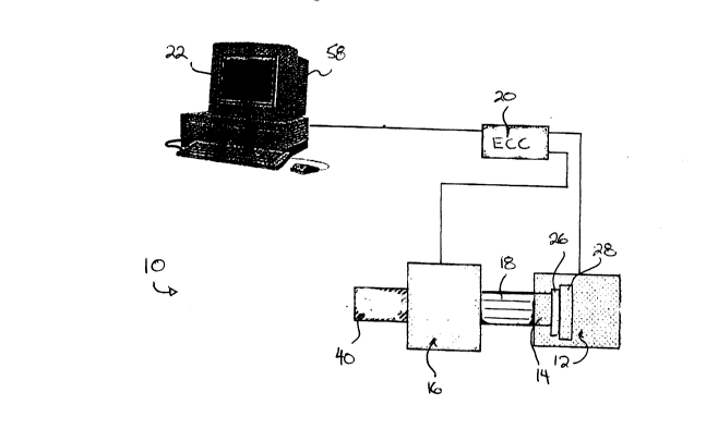
Reference is made first to Figure 1, which shows
an image intensifier system 10 in accordance with a first
embodiment of the invention. The system 10 includes an
integrating video camera 12 which incorporates a CCD
element 14, an image intensifier 16 and a fibre optic
coupler 18 optically coupling the intensifier 16 to the
- ~57755
- 13 -
front of the camera 12. An external camera control 20
(ECC) contains circuitry for controlling the camera and
conditioning the signal. A computer 22 is also provided
coupled to the input and output of the camera control unit
20 for software-driven control of the system operation and
storing of output images.
Figures 2 and 3 show best the camera 12 for use
with the system 10. The camera 12 includes a CCD element
14 positioned behind a camera aperture 25. To reduce dark
noise produced by electrons within the CCD element, the CCD
element 14 is mounted to a heat sink 26, which in turn is
thermally coupled to a Peltier cooling element 28 for
providing enhanced heat dissipation. An electronic shutter
mechanism 32 is additionally provided within the camera 12
for limiting the exposure of the image on the CCD element
14. Preferably the camera 12 is a high resolution 768H x
482V pixel black and white full frame shutter camera, with
asynchronous reset capability and uniform modulation
transfer characteristic functions. The camera 12 provides
an 8-bit digital signal output via a standard digital
interface protocol 34 such as EIA-422. An interlaced or
progressive scan analog output is available from an
integral frame buffer 36. The flexible provision of both
digital and analog output permits the camera 12 to be used
as a stand alone unit, with a display monitor, or as part
of a computer image analysis system.
The camera 12 operation is controlled externally
by the camera control unit 20. The control unit 20
controls the integration time of the camera 12, adjusts the
intensifier gain, and adjusts the video gain and black
level of the camera 12. The camera control unit 20
includes the asynchronous reset circuitry which operates to
accentuate edges in the image. This circuit can be useful
in restoring some of the edge degradation produced when
21~7 ~5~
- - 14 -
using the system 10 at high gain factors.
Image averaging circuits 38 are also provided in
the camera 12 to decrease noise. Data from the CCD element
14 are digitized and fed to the internal frame buffer 36.
As each frame arrives at the buffer 36, it is passed
through an arithmetic logic unit which performs iterative
averaging of the incoming frame with previous frames.
Although most image analyzers report data with 8 bit (256
level) precision, video cameras provide only about 45-50 dB
of signal-to-noise ratio for any individual pixel.
Intensifiers are much worse, particularly at high gain.
The present system 10 therefore is additionally provided
with noise reduction circuitry to provide noise reduction
by frame averaging. With such circuitry, as the number of
frames imaged by the camera 12 increases, the root mean
square noise amplitude decreases by a factor of 1 / V~~~
(where n is the number of frames).
In addition to controlling the operation of the
camera 12 and the intensifier 16, the camera control unit
20 outputs the integrated data to the computer 22 where it
may be stored, output to a video terminal 58 or a printer
(not shown) or the like.
The asynchronous reset capability of the camera
12 is flexible, and takes external horizontal
synchronization for phase locking to a trigger. When an
initialization pulse is applied by the camera control unit
20, it resets the camera's scanning, and purges the CCD
element 14. At that point the image is transferred from
the CCD element 14 to the internal frame buffer 36.
The shutter mechanism 32 is of a substrate drain
type and provides rapid clearing of the CCD element
charges, so that the camera 12 may be used at high shutter
speeds without smearing of images. This feature is
- 21~775~
- 15 -
particularly useful if the camera 12 is operated in photon
counting mode.
Figure 4 shows best the intensifier 16 as being
of the GEN III type and including a lens 40, a
photosensitive cathode 42, a microchannel plate (MCP) 44,
a phosphor screen 46, and a vacuum sealed body 48 or
enclosure. The lens 40 is a high-numerical aperture
design, which captures light very efficiently. The lens 40
focuses to within 30 cm, and permits system 10 to be used
to image almost any specimen. At its output, the lens 40
is focused on an input window of the cathode 42 so as to
transfer the specimen image thereto. The photosensitive
cathode 44 is selected to emit electrons in proportion to
the intensity of light falling upon it. The microchannel
plate (MCP) 44 is positioned within the vacuum sealed body
48, between and coupled at each end to the cathode 42, and
the phosphor screen 46. The MCP 44 is provided with an
array of small diameter MCP channels 50, each of the MCP
channels 50 are coated with gallium arsenide. The
electrons emitted from the cathode 42 are accelerated along
the MCP channels 50 to the phosphor screen 46. As the
electrons from the cathode 42 are accelerated along the
small diameter channels 50, they strike the coated channel
walls to produce additional electrons. As the multiplied
electrons leave the MCP channels 50, they strike the
phosphor screen 46 and produce an intensified image of the
specimen on an output screen 52.
It has been found that the use of the Extended
Blue GEN 3 image intensifier 16 is advantageous over other
types of intensifiers in that the image provided on the
output screen 52 is sharper, has less shading error, and
has less noise than those produced by GEN 1 and GEN 2
intensifiers. It is to be appreciated, however that as
better intensifier technologies are developed, they may
21577~
- 16 -
equally be incorporated into the present system 10.
The fibre optic coupler 18 is preferably a bonded
fibre optic coupler used to couple the output screen 52 of
the intensifier 16 directly to the CCD element 14 of the
video camera 12. Direct fibre optic coupling of the
intensifier 16 to the camera CCD element 14 is four to
eight times more efficient than a lens in transferring
light from the output screen 52 to the camera 12. In the
present case, the fibre optic coupler 18 includes a fibre
optic input window 60 and a fibre optic minifier 62. The
minifier 62 provides a 1.5:1 fibre optic taper to a smaller
fibre optic output window 64 which is bonded to the CCD
element 14. The 1.5:1 reduction ratio of the minifier 62
has been found to allow full use of the highest resolution
obtainable from the image intensifier 16. It will present
an image having over 76 linepairs/mm to the CCD element 14,
with distortion of less than 3% and overall light
transmission of >75~.
In use of the system 10, the intensifier lens 40
is adjusted to focus a bioluminescent or fluorescent
specimen on the input window of the intensifier
photocathode 42. The photocathode 42 emits electrons in
proportion to the intensity of light from the specimen
falling upon it. A voltage is applied to the emitted
electrons as they move from the photocathode 42 into the
MCP 44, thereby accelerating the electrodes as they enter
the small diameter MCP channels 50. Within the thousands
of MCP channels 50, the electrons collide with the coated
channel wall surfaces and dislodge additional secondary
electrons. In this manner, one input electron can generate
thousands of secondary electrons to provide light
amplification. The electrons are accelerated again as they
leave the MCP 44, and then strike the phosphor screen 46 on
its inner surface, to generate a visible image on the
~5~75~
output window 52. The visible image is then transferred
from the output window 52 to the camera 12 by the fibre
optic coupler 18.
The integrating camera is configured so that the
highly amplified image generated on the output window 52 is
focused by the lens 40 and coupler 18 onto the CCD element
14. To image low light specimens, the CCD element 14
integrates for a period of at least one second, accepting
a trigger pulse from the camera control unit 20 to initiate
the operation of the electronic shutter 32. The electronic
shutter clears the CCD element 14, from which point the
image is transferred to the internal frame buffer. For
very dim specimens, a period lasting from two or more
seconds upwards to more than one minute may be used.
During the integration period, photons from the output
window 52 incident to the CCD element 14 are stored as
negative charges (the Signal) in numerous discrete regions
of the CCD element 14. The amount of the charge in each
discrete region of the CCD element 14 is accumulated as
follows.
Signal = Incident light x Quantum efficiency x
Integration time
The greater the relative intensity of the incident light
coming from the intensifier 16, the greater the signal
stored in the corresponding region of the CCD element 14.
Upon completion of the integration period, a
signal representative of the specimen image is exported
from the camera 12 to the computer 22 for output or further
image averaging externally by the computer 22.
As the present invention is designed for imaging
very dim specimens, and as the gain available from an
- 215775~
- 18 -
intensifier is limited, relatively long periods of
integration of the intensifier output onto the cooled
integrating camera 12 are provided. For chemiluminescent
blots, integration periods of 10 sec to 1 minute can be
used, equivalent to a film exposure of about 1 minute to 4
minutes. For more dim specimens, multiple 10 sec to 1
minute exposures are necessary, and frame averaging by the
control unit 20 (typically four frames) may be used to
improve signal to noise ratio in a final output image.
Figure 1 shows the CCD camera 12 as being
provided without an image averaging circuit with image
averaging done externally on a personal computer 22. If
desired, image averaging may equally be accomplished within
the camera 12 itself or within the camera control unit 20,
by the addition of image averaging circuitry. Figure 5
illustrates schematically a modified system 10 wherein like
reference numerals are used to identify like components and
in which the camera~unit 20 incorporates image averaging
circuitry and outputs the final image as an analog signal
sent to a display monitor 70.
Although the camera 12 could be used without
cooling the CCD element 14, extended periods of integration
are achieved by using a CCD camera with an integral cooling
element. The effectiveness of integration is limited by
the degree of cooling. With thermionic cooling using a
standard Peltier cooling device, sensor temperatures of
about -20C can be achieved. This allows integration for
periods of up to about two minutes before background noise
becomes bothersome. Thermionic cooling has the advantage
of low cost and easy implementation.
It is to be appreciated, however, that longer
periods of integration are possible if multistage
thermionic, liquid, or cryogenic cooling are employed.
These more effective cooling methods would be combined with
~157;7~
..
-- 19 --
a more sophisticated camera, capable of higher precision
(10-16 bits is typical). Using a high precision liquid
cooled camera does achieve better image quality and higher
sensitivity, but with a corresponding increase in the cost
of the camera.
In addition, with the system 10 shown in Figure
1, only the CCD element 14 is cooled. This is sufficient
for routine imaging. It is to be appreciated however, that
for more demanding tasks, the photocathode 42 could also be
cooled, thereby improving the signal to noise ratio of the
intensifier 16. Similarly, the entire photosensitive
apparatus (i.e. intensifier and CCD) can be cooled.
However, cooling the entire photosensitive apparatus has
the disadvantage that the efficiency of the phosphor on the
fibre optic output window is decreased.
In the preferred embodiment of the invention
shown in Figure 1, the system 10 incorporates an Extended
Blue type of GEN 3 image intensifier 16. Other types of
intensifiers, although less preferred, may also be used.
The three major types of intensifier (GEN 1, GEN 2 and GEN
3) differ in the organization of their components and in
the materials of which the components are constructed. In
a GEN 1 intensifier, illumination incident to a
photocathode results in emissions at a rate proportional to
the intensity of the incident signal. The electrons
emitted from the photocathode are then accelerated through
a high potential electric field, and focused onto a
phosphor screen using electrostatic or proximity focusing.
The phosphor screen can be the input window to a video
camera (as in the silicon intensified target camera), or
can be viewed directly. GEN 1 intensifiers, however,
suffer from bothersome geometric distortion, and have
relatively low quantum efficiency (about 10~).
21~775~
- 20 -
The GEN 2 intensifiers, like the GEN 3,
incorporate a MCP into an image tube, between the cathode
and an anode. The GEN 2 intensifiers are smaller, lower in
noise, and have higher gain than the GEN 1 intensifiers.
However, their quantum efficiency is fairly low (typically
<20%), and they tend to suffer from poor contrast transfer
characteristics. In contrast, the GEN 3 intensifier tube
has a quantum efficiency of about 30% or higher (needs less
gain), and very high intrinsic contrast transfer. With
recent versions of the GEN 3, gain levels are about equal
to those of a GEN 2 (ultimate gain level available is about
90,000). Therefore, a GEN 3 intensifier will tend to yield
better images than a GEN 2. Where necessary for reasons of
cost or specific design features, other forms of
intensifier could be used. Similarly devices with high
intrinsic gain (such as electron bombarded back-illuminated
CCD sensors) could be used in place of image intensifiers.
The CCD camera 12 of the present invention uses
an asynchronous reset which takes an external drive signal
from the control unit 20 for phase locking. When the
signal is applied, it resets the camera 12, also sc~nn;ng
and purging the CCD element 14. As the CCD camera 12
incorporates mechanisms that provide very low lag, short
integration periods (e.g. 1/16,000 second) can be used. If
desired, these integration periods can be locked to a gated
power supply (not shown) in the image intensifier 16, with
the result that the camera 12 can be read out at very short
intervals. Using the gating and fast readout feature, and
with the intensifier 16 run at highest gain or with a
multistage intensifier 16, the present invention can
thereby be operated as a conventional photon counting light
imaging system. Thus, the present system 10 can
advantageously be used for both direct imaging of faint
specimens, or as a standard photon counting camera by
changing its mode of operation from integration to gating.
21~i77~i~
While the preferred embodiment of the invention
discloses the use of a cooled CCD element 14, for
relatively bright specimens, if cost is a major factor, the
present invention could be constructed without cooling
element 28. In this case, a camera 12 could be constructed
at quite a low cost and integration periods of about 5
seconds can be achieved, albeit with a reduction in image
quality and ultimate sensitivity.
Although the preferred embodiment of the
invention illustrates a bonded fibre optic coupler 18 with
a minifier 62 for coupling the intensifier 16 to the video
camera 12, the invention is not so limited. If desired the
image intensifier 16 could also be coupled to the
integrating camera using a lens, a conventional fibre optic
coupler or any other suitable optical coupling device.
Although the detailed description describes and
illustrates preferred embodiments of the present apparatus,
the invention is not so limited. Modifications and
variations will now appear to persons skilled in this art.
For a definition of the invention reference may be had to
the appended claims.