Note: Descriptions are shown in the official language in which they were submitted.
2157852
272/068 CIP
DYNAMO-ELECTRIC MACHINE COMPONENT
CONVEYING SYSTEMS AND LOAD/UNLOAD DEVICES
Background of the Invention
The present invention relates to improving
conveying systems for transporting dynamo-electric
machine components between a series of processing
machines of an automatic, parallel processing,
production line, and for delivering such components to
a selected one of the series of processing machines for
processing. More particularly, the present invention
relates to conveying systems for transporting dynamo-
electric machine components (e.g., electric motor
parts) having magnetic cores between a main conveyor
and a selected one of a series of processing machines
working in parallel along the main conveyor. The
present invention further relates to load/unload
devices for transferring dynamo-electric machine
components between the main conveyor and the selected
processing machines. Dynamo-electric machine
components are loaded directly from the main conveyor
line onto a load/unload device, and from the
load/unload device onto the selected processing machine
in a time-efficient manner. The load/unload device has
two component holders (e.g., collets) movably mounted
on a base platform for alternate alignment for loading
and unloading of dynamo-electric machine components.
The load/unload device moves between the main conveyor
2157852
-- 2
and the selected processing machine while the central
axis of the load/unload device preferably remains
fixed.
Automatic manufacturing lines for processing
dynamo-electric machine components having a magnetic
core (hereinafter "components") typically transport the
- components between a variety of machines. (By
"magnetic core" it is meant that the core is
magnetizable, not that it is necessarily magnetized at
all times.) For example, armatures are conveyed to
such machines as winding machines and fusing machines.
The present invention is specifically related to
conveying such components as armatures to any type of
machinery or processing apparatus that
characteristically is used in parallel with at least
one other identical machine on a particular conveyor
section. These machines typically have slower
production rates than machinery that is not used in
parallel production lines (i.e., machinery in
manufacturing lines where only one machine of a
particular type is present on the line). These
machines also usually require the components to be
removed from the pallets on which they are conveyed in
order to be processed. Once processing has been
accomplished, the component is returned to an empty
pallet for transport to other downstream machines of
the manufacturing line.
One example of a conveying system is shown in
FIG. 1. A main conveyor section 100 transports pallets
carrying components such as armatures to any one of the
machines 102, 104, and 106 of the same type.
Additional conveyors 112, 114, and 116 are placed in
front of respective machines 102, 104, and 106 for
conveying to a selected machine components to be
processed. Transfer devices 122, 124, and 126 remove
2157852
-- 3
pallets carrying components to be processed from main
conveyor section 100 and transfer the pallets to the
additional conveyors 112, 114, and 116, respectively.
once a pallet is on one of additional
conveyors 112, 114, 116, the component it is carrying
can be transferred to a corresponding machine 102, 104,
- 106 for processing. The pallet can then receive a
processed component from the machine along which the
pallet is conveyed. After the pallet receives a
processed component, the pallet can move to the
downstream transfer device 132, 134, 136 associated
with the additional conveyor on which the pallet is
conveyed, and be returned to main conveyor section 100.
The pallet, now carrying a processed component (such as
a wound armature), is subsequently transferred to
further conveyor section 110.
The pallets that carry the components for
processing are typically provided with coding devices
which indicate the processing condition of the
component being carried. More precisely, these devices
indicate whether a component has or has not been
processed by one of machines 102, 104, 106. Writing
devices may also be used to change the coding
information so that the device indicates that the
component has been processed.
Devices for reading the coding devices are
placed before transfer devices 122, 124, and 126 to
determine whether a pallet needs to be transferred to
an associated machine for processing. If the pallet
need not be transferred (because the component it is
carrying has already been processed), the pallet
travels to the end of main conveyor section 100 for
transfer to further conveyor section 110. Reading of
the coding device occurs each time a pallet reaches one
of transfer devices 122, 124, 126. The pallets are
- - 2157852
stopped against an abutment surface in order to have
their coding devices read while the transporter belts
continue to move. Before a pallet is transferred to
further section 110, another reading of the coding
device is performed to determine whether the pallet is
carrying an unprocessed component and needs to be
- returned to the beginning of main conveyor section 100.
Additional conveyor sections 112, 114, and
116 are provided with devices for determining how many
pallets are queued up on the selected conveyor waiting
to deliver a component to a corresponding machine 102,
104, 106. If the number of pallets on a particular
additional conveyor section is at the maximum, then
transfer by the transfer device related to that
particular section will not transfer a pallet to that
section until a place for another pallet is created.
Thus, pallets having components which need to be
processed travel down main conveyor section 100 until
they find a free additional conveyor section 112, 114,
116. If the pallet reaches the end of main conveyor
section 100 without having found a free additional
conveyor section (e.g., because machines 102, 104, and
- 106 are all occupied), then transfer device 140
transfers the pallet to return conveyor 142, and
transfer device 144 returns the pallet to the beginning
of main conveyor section 100. ~he pallet then once
again attempts to find a free additional conveyor
section 112, 114, 116, as described above.
A possible disadvantage of this type of
conveying system in some situations is the delays that
occur while pallets and components are transferred.
When pallets are transferred by transfer devices 122,
124, 126, 132, 134, 136 between main conveyor
section 100 and additional conveyor sections 112, 114,
116, pallets upstream of the pallet being transferred
- 2157852
are halted to allow the transfer to occur. Loading and
unloading of components between pallets on additional
conveyor sections 112, 114, 116 and machines 102, 104,
106 occurs by stopping the pallet in front of the
associated load/unload device 152, 154, 156, removing
the component to be processed, and placing on the now
- empty pallet a processed component so that the pallet
can be transferred back to main conveyor section 100
without waiting for completion of processing of the
component it had delivered.
Another characteristic of systems of the type
shown in FIG. 1 is that the additional conveyor
sections tend to require additional floor space and may
increase the maintenance requirements of the system.
As shown in FIG. 1, five different conveyor sections
must continue to run smoothly for the conveying system
to be fully operational.
Finally, load/unload devices 152, 154, 156
may be regarded as relatively slow in transferring
components between additional conveyor lines 112, 114,
116, and machines 102, 104, 106, respectively.
A second type of conveying system is shown in
FIG. 2. A main conveyor 200 transports pallets
carrying components to a number of machines, such as
winder 202, in a parallel processing system. When a
pallet carrying a component to be processed approaches
an available machine, the pallet is transferred to a
secondary conveyor 210, which is preferably
perpendicular to main conveyor 200. From secondary
conveyor 210, the component to be processed is
transferred to a collet on carriage 220. Carriage 220
is positioned on slide 230, which is cantilevered from
support 240. Slide 230 slides in direction 232 to
bring carriage 220 adjacent secondary conveyor 210 in a
plane spaced above the plane of secondary conveyor 210.
- - 2157852
As viewed in FIG. 2 the stopping point of slide 230 is
below the depicted location of the pallet on secondary
conveyor 210. The component on this pallet is then
lifted off the pallet. Carriage 220 slides laterally
on slide 230 along direction 222 to alternately align
collet 226 with the pallet (to receive a component from
- the conveying system for processing) and to align
collet 224 with the pallet (to return a processed
component to the conveying system). Slide 230 slides
along direction 232 to transport carriage 220 to
winder 202 to load a processed component onto
collet 224 (then aligned with winder 202).
Carriage 220 then slides along direction 222 to deliver
a component to be processed, carried by collet 226, to
winder 202. Slide 230 then slides back to additional
conveyor 210 to repeat the above steps.
Because this conveying system also uses
additional conveyor lines 210 to which pallets are
transferred, this system may also have the above-
described possible disadvantages of time delays during
pallet transfer, the necessity of additional floor
space, and increased maintenance requirements. The
length of travel of slide 230 also tends to be quite
long.
A third type of a conveying system, described
in Nussbaumer U.S. patent 4,718,533, does not use
additional conveyor sections (such as those shown in
FIG. 1). When a pallet needs to be loaded or unloaded
at a particular machine, the pallet is lifted off the
main conveyor so that pallets that need to reach adownstream portion of the conveyor line can travel
beneath the lifting device. This system tends to
require complicated pallet-lifting equipment.
In view of the forego-ng, it would be
desirable to provide a conveying system and method that
2157852
would quickly and efficiently convey components to be
processed through a manufacturing line, and transport
the components between the means conveying the
components and the machines in the manufacturing line.
S It would also be desirable to provide a
conveying system and method that would not require
- conveyor lines in addition to the main conveyor line or
complicated pallet lifting equipment that may tend to
increase machinery costs and require large areas of
manufacturing plant floor space.
It would further be desirable to provide a
load/unload device and method that quickly and
efficiently transports components between a conveyor
line and a processing machine.
SummarY of the Invention
It is therefore an object of this invention
to provide a system and associated method for quickly
and efficiently conveying components to be processed
through a parallel processing production line, and
transporting the components between the means conveying
the components and the machines in the production line.
It is also an object of this invention to
provide a conveying system and method that does not
require conveyor lines in addition to the main conveyor
line or complicated pallet lifting equipment that tends
- to increase machinery costs and require large areas of
manufacturing plant floor space.
It is a further object of this invention to
provide a load/unload device and method that quickly
and efficiently transports components between a
conveyor line and a processing machine.
These and other objects are accomplished in
accordance with the principles of this invention by
providing a system having a main conveyor for conveying
- - 21578~2
components (defined above to mean dynamo-electric
machine parts having a magnetic core) along a series of
machines in a parallel processing system, and a
load/unload device adjacent each machine for
transferring components between the adjacent machine
and the main conveyor. The load/unload device is
~ movable between the main conveyor and the processing
machine with which the particular load/unload device is
associated. The load/unload device has a base platform
for carrying a movable carriage on which at least two
component holders such as collets are positioned. The
base platform has an alignment area at which a
component holder is positioned for transfer of a
component. Each time the alignment area is positioned
for a transfer, the component holders are sequentially
positioned at the alignment area for delivery of a
component from one component holder and receipt of
another component by another component holder.
The number of pallets present in a particular
conveyor section of the conveyor line depends on the
upstream supply of the conveyor line and also on the
productivity of the machinery being supplied by a
related conveyor section. The conveyor has belts that
move continuously during manufacturing to move the
pallets between machines in the conveyor/manufacturing
line. The conveyor sections transport the components
between machines such as winding machines, fusing
machines, or any type of machinery that
characteristically has more than one machine working in
parallel on a particular conveyor section.
Brief Description of the Drawings
The above and other objects and advantages of
the invention, its nature, and various advantages will
be apparent from the following detailed description of
- - 21~7852
the preferred embodiments, taken in conjunction with
the accompanying drawings, in which like reference
characters represent like elements throughout, and in
which:
FIG. 1 is a schematic plan view of a prior
art system using additional conveyor sections and
- load/unload devices which transfer components between
pallets and processing machines;
FIG. 2 is a schematic plan view of a prior
art system using an additional conveyor section and a
slidable carriage for transferring components between
pallets on the conveyor section and processing
machines;
FIG. 3 is a schematic plan view of an
illustrative embodiment of the conveying system of the
present invention;
FIG. 4 is a graphic representation of the
time required to transport components between a prior
art conveying system and one of a series of processing
machines, compared with a graphic representation of the
time required to transport components between the
conveying system of the present invention and one of a
series of processing machines;
FIG. 5 is an isometric view of an
illustrative embodiment of the conveying system and
load/unload device of the present invention;
FIG. 6 is a schematic plan view of the
conveying system and loadtunload device of FIG. 5,
showing the load/unload device loading and unloading
components onto and from the main conveyor; and
FIG. 7 is a schematic plan view of the
conveying system and load/unload device of FIG. 5,
showing the load/unload device loading and unloading
components onto and from a selected machine along the
production line.
- 2157852
-- 10 --
FIG. 8 is a schematic plan view of an
alternative conveyor system constructed in accordance
with this invention.
FIG. 9 is a simplified sectional view of a
representative portion of the apparatus shown in
FIG. 8.
- FIG. 10 is a simplified timing diagram
showing various aspects of an illustrative operating
sequence of the apparatus shown in FIG. 8.
FIG. 11 is a view similar to FIG. 8 showing
another alternative conveyor system constructed in
accordance with this invention.
FIG. 12 is still another view similar to
FIG. 8 showing still another alternative conveyor
system constructed in accordance with this invention.
FIG. 13 is a simplified elevational view of
illustrative component sensor apparatus constructed in
accordance with this invention.
FIG. 14 is a simplified elevational view of
illustrative more fully processed component sensor
apparatus constructed in accordance with this
lnvention.
Detailed Description of the Preferred Embodiments
A conveying system 300 for a parallel
processing system/production line in accordance with
the principles of the present invention is shown
schematically in FIG. 3. System 300 only has one main
conveyor 310 from which components to be processed are
removed for processing and to which processed
components are returned. Main conveyor 310 extends
along all of the processing machines in the series of
processing machines of the production line. It will be
understood that main conveyor 310 is referred to as a
single conveyor, but may be several separate, aligned
" 21S7852
conveyors forming a continuous conveyor line extending
along all of the processing machines in the series. A
return conveyor 312 is present to return unprocessed
components that could not be processed during their
first pass along conveyor 310 (e.g., because all the
machines or load/unload devices were occupied when the
- component passed by) to the beginning of main
conveyor 310 to once again convey the components
through the system. While on conveyors 310 and 312
each component is supported on a pallet 320. Each
conveyor 310, 312 preferably has two parallel conveyor
belts, as shown in further detail in FIG. 5, and as
described in further detail below. It will be
understood that any other means for transporting
components (or pallets) between the processing machines
in the system may be used.
Conveyor 310 carries the components to
load/unload devices 322, 324, and 326, which load and
unload components to and from processing machines 332,
334, and 336, respectively. Main conveyor 310 extends
between all of processing machines 332, 334, 336.
Load/unload devices 322, 324, and 326 can load and
unload components in a very short time, as will be
described in further detail below. Accordingly,
additional conveyors parallel or perpendicular to main
conveyor 310, such as are employed in the prior art,
are not necessary to transport components to the
relatively slow processing machines to be used in the
present invention.
When a pallet reaches a load/unload
device 322, 324, 326, if the component carried thereon
needs to be processed, then the pallet is halted to
allow for unloading of the component onto the
load/unload device and subsequent loading of the pallet
with a processed component. Pallets upstream of the
2157852
- 12 -
pallet being loaded/unloaded are halted while
loading/unloading occurs. Because the time required to
load/unload a component is extremely short, the
conveying system is capable of operating at
approximately the same production rate of a parallel
processing system of the prior art having the same
~ number of processing machines 332, 334, 336.
Preferably the component transfer times in the systems
of this invention are less than those in prior art
systems. But even if the present transfer times are
slightly greater than in prior art systems, the overall
production rate and/or average efficiency of
utilization of the production machines may be the same
- as or greater than in prior systems. This will now be
explained in more detail.
A comparison of time graphs relating to the
operation of the prior art system of FIG. 1 (requiring
an additional parallel conveyor section) and the
operation of the present system is shown in FIG. 4. In
graph (a), time T1 is the time required by the prior
art system of FIG. 1 for the entire unloading of a
component to be processed from the conveyor and
subsequent loading of a processed component onto the
conveyor. Time T1 causes halting of the pallets and
therefore stops supply of the pallets to the machines.
This time includes time TA for halting a pallet and
reading its coding device, time TB for transferring a
pallet from the main conveyor section to the additional
conveyor section, and time TC for ~ransferring a
pallet from the additional conveyor section to the main
conveyor section. In contrast, in graph (b), the time
Tl is the total time required for the load/unload
device of the present invention to remove a component
to be processed from a pallet on the main conveyor and
to load a processed component on the same pallet --
2157852
- 13 -
achieving the same effect as all the steps of graph (a)
in a practically equal if not shorter time. Time T1
also corresponds to the time during which pallets are
halted and accordingly determines the delay for the
pallets that have been halted to reach successive
machines for processing. The time delay for halting
- pallets is a basic parameter for determining the
production capacity of any of the systems that are
described herein. That time delay is also a parameter
for determining the efficiency with which the machines
placed in the parallel processing production line are
used.
A comparison of the production capabilities
of the systems of FIGS. 1 and 3 begins by noting that
the two systems have the same number of production
machines (e.g., winders), which means that they are
theoretically capable of producing the same production
rates. In practice, the machines of each system will
only be used for a fraction of their maximum possible
production rate. This fraction depends on the
conveying system with which the machine is working and
is influenced by the timing of the system to supply
pallets to the machines. In the system of FIG. 1, this
timing depends on the time to unload and to load the
pallets off and on conveyor 100 and the time to read
the code of the pallet at points 122, 124, or 126. In
the system of FIG. 3 this timing depends on the time
that a pallet is required to stop at a machine in order
to unload and load components between load/unload
device 322, 324, or 326 and the pallet.
The fraction of a machine's maximum
production capability that is actually used is often
defined as the "efficiency" of use of the machine. A
comparison between the systems of FIGS. 1 and 3 should
include an examination of this efficiency fraction for
21S78S2
the individual machines which are present in the
systems. For the system of FIG. 1 this efficiency
fraction is very high (e.g., 99%) for the first machine
of the system (the one on the extreme left), a little
lower (e.g., 98%) for the machine in the middle, ànd
much lower (e.g., 95~) for the machine on the extreme
- right. For the system of FIG. 3 the efficiency
fraction descends more gradually from the first machine
(on the left) to the last machine (on the right) (e.g.,
99% for the first machine, 98% for the middle machine,
and 97% for the last machine). These results show that
the system of FIG. 3 is capable of obtaining high
production rates from the overall system and a more
uniform distribution of efficiency of use among the
machines. This last consideration is a positive aspect
because it means that all the machines are being used
near to their highest capabilities of producing.
Finally, the system of FIG. 3 has an important
advantage over the system of FIG. 1 because it requires
less conveying equipment, occupies less floor space,
and can function well even without coding devices on
the pallets.
The times T1 and T1 shown in the graphs of
FIG. 4 coincide with the times described above for
reaching the above-mentioned conclusion regarding the
comparison between the system of FIG. 1 and the system
of FIG. 3. In the FIG. 4 graphs the time T1 for the
system of FIG. 1 is shown as being longer than the time
T1 of the system of FIG. 3. However, the same
conclusion regarding comparison between the systems of
FIGS. 1 and 3 can be reached even if time T1 is
somewhat shorter than time T1. The irregularity with
which the interruption of pallet supply occurs in the
system of FIG. 1 can result in the system of FIG. 3
being more productive and/or having more uniformly
21578 5 2
distributed production than the system of FIG. 1 even
if T1 is slightly less than T1.
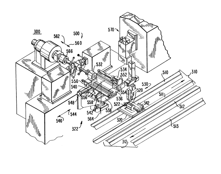
A conveying system 300 and load/unload
device 322 (which is substantially identical to
devices 324 and 326) for use in an armature winding
production line/parallel processing system in
- accordance with this invention are shown in greater
detail in FIG. 5. (See also FIGS. 6 and 7 which show
the load/unload device of FIG. 5 in different positions
and operating conditions.) As shown, a pallet 320 is
carried by main conveyor 310 to load/unload device 322.
Main conveyor 310 preferably has two parallel belts 510
and 511 which continuously move between machines in the
system. Likewise, return conveyor 312 preferably has
two parallel belts 512 and 513 which continuously move
pallets carrying components that need to be processed
from the end of main conveyor 310 to the beginning of
main conveyor 310. The two belts 510 and 511 that are
used in main conveyor 310 preferably are spaced apart a
sufficient distance to allow a movable stop 342 to come
up between the belts and stop a pallet 320 under
gripper 530.
A gripping device 530 (such as the gripping
device described in Santandrea et al. U.S. patent
5,257,689 or Andorlini et al. U.S. patent 5,253,912)
descends and then grips, lifts, and removes
armature 520 from the stopped pallet. Gripping device
530 also rotates 180 about its vertical axis as it
lifts armature 520. This reverses armature 520 end for
end from its position on pallet 320.
When collet 532 of load/unload device 322 is
aligned with gripping device 530 at an alignment area
associated with load/unload device 322 (see FIG. 6 for
this condition of load/unload device 322, although
FIG. 6 shows a differently numbered armature 600 prior
` _ 21S7852
- 16 -
to the above-mentioned 180 rotation of gripping device
530), collet 532 removes armature 520 from gripping
device 530. Collet 534 should already be gripping a
wound armature it received from winder 500 (unless the
conveyor system has just begun processing components)
and waiting alongside collet 532, not aligned with
~ gripping device 530. Collets 532 and 534 may be any
desired component holding devices, and preferably in
this instance are collets designed and shaped to hold
an armature, such as shown in Lombardi U.S. patent
5,178,428. In the particularly preferred embodiment
shown in the drawings collets 532 and 534 grip the
shafts of armatures 520 remote from the commutator end
522 of the armatures. This is done so that the
commutator end of the armature can be inserted in
winding machine 500 (and fusing machine 570 if a fusing
machine is included as shown in FIG. 5).
Collets 532 and 534 preferably are positioned
on carriage 536, which is slidable on base 538 along
tracks 540 and 542 (in directions 544 and 546, parallel
to the transverse axis of base 538). Base 538 (and
therefore everything mounted on base 538) is rotatable
about vertical axis 564. The alignment area of
load/unload device 322 is determined with respect to
base 538. Sliding of carriage 536 is actuated by
pneumatic cylinder 548. It will be appreciated that
collets 532 and 534 may be directly slidably mounted on
base 538 instead. Once collet 532 receives a component
to be processed, in this case an unwound armature,
carriage 536 slides in direction 544 to align
collet 534, carrying a wound armature, with
gripper 530. Thus collet 532 moves away from the
alignment area of load/unload device 322 and collet 534
moves into the alignment area. Collet 534 transfers
the wound armature to gripper 530, which rotates 180
21S7852
- 17 -
about its vertical axis and descends to place the
armature on the pallet below the gripper. It will be
understood that a component may be transferred between
pallet 320 and one of collets 532 and 534 without the
use of gripping device 530 or by means other than
gripping device 530. For example, an armature lifting
- device could come up below armature 520 throuqh the
central aperture in pallet 320 to raise the armature
off the pallet. (See, for example, Santandrea et al.
U.S. patents 5,060,781 and 5,115,901 for discussions of
this type of apparatus and suitable pallets.)
In order to transfer armatures between
collets 532 and 534 and gripper 530, each collet slides
along its longitudinal axis to approach and withdraw
from gripper 530. Collets 532 and 534 are respectively
mounted on collet carriages 550 and 552, which
respectively slide along slides 554 and 556, parallel
to the longitudinal axes of collets 532 and 534. A
pneumatic cylinder, such as cylinder 558, actuates
translation of each collet carriage along the
longitudinal axis of the collet as desired. It will be
understood that any other means for translating
collets 532 and 534 may be used. Preferably each
collet has a rest position at which the rear end of the
collet (the end opposite the gripping portion of the
collet) is positioned at the end of its respective
track and the gripping portion of the collet is
positioned substantially completely above carriage 536.
Thus, to approach gripper 530 (when base 538 is rotated
about axis 564 so that the gripping portion of the
collet is facing gripper 530), a collet moves in
direction 560. To return to its rest position, the
collet moves in direction 562.
once a wound armature (or other processed
component) is removed from collet 534, carriage 552
215785 2
- 18 -
returns collet S34 to its rest position (collet 532
should already be in its rest position) and base 538 is
rotated 180 about the central axis 564 of load/unload
device 322 (see also FIG. 7 for this condition of the
load/unload device). Central axis 564 remains at a
fixed location. Preferably, when rotation occurs, both
~ collets are in their rest positions. A motor,
reduction gear, and gear mechanism, or any other
desired mechanism, such as intermittors, can be used to
rotate base 538. It will be understood that winder 500
need not be directly opposite main conveyor 310, and
therefore base 538 may be rotated greater or less than
180 about axis 564. Carriage 536 maintains its
position relative to base 538 during rotation. Thus,
collet 534, which is now empty, is now aligned with
winder 500.
Collet carriage 552 advances collet 534 in
direction 562 toward winder 500 to remove a wound
armature from winder collet 566, and then returns
collet 534, along direction 560, to its rest position.
If desired, a gripper such as gripper 530 may be used
to transfer the wound armature from winder collet 566
to collet 534. Carriage 536 then translates along
direction 544 to align collet 532, carrying an unwound
armature (or other unprocessed component), with
winder 500. Collet carriage 550 advances collet 532 in
direction 562 toward winder 500 to deliver the armature
for winding, and then returns collet 532, along
direction 560, to its rest position. Once again, if
desired, a gripper such as gripper 530 may be used to
transfer the unwound armature from collet 532 to winder
collet 566. Base 538 then rotates 180 along central
axis 564 to have the gripping portions of collets 532
and 534 once again face gripper 530 so that the cycle
can be repeated. Alternatively, base 538 can rotate
2157852
- 19 -
90 to have the gripping portions of collets 532 and
534 face another processing machine such as fusing
machine 570, and a similar exchange of processed
components for components to be processed occurs before
returning base 538 to its initial position with the
alignment area adjacent main conveyor line 310.
- (Fusing machine S70 may be a conventional device for
producing finished mechanical and electrical
connections between the leads of the coils wound on the
armature by winder 500 and the commutator segments to
which those coil leads extend.) Preferably, when
rotation of base 538 occurs, both collets are in their
rest positions.
Schematic plan views of conveying system 300,
showing the steps involved in loading and unloading
load/unload device 322, are illustrated in FIGS. 6
and 7. In FIG. 6, collet 532 is shown aligned with an
unwound armature 600 (any other component to be
processed may be used) carried by pallet 320, i.e.,
collet 532 is shown at the alignment area of
load/unload device 322. Armature 600 is halted on main
conveyor 310 awaiting transfer (such as by means of
gripper 530) to load/unload device 322. If gripper 530
is used, gripper 530 lifts unwound armature 600 from
pallet 320 and rotates it 180 as described above.
Collet 532 advances in direction 560 toward gripper 530
to receive unwound armature 600, and then retreats in
direction 562 to its rest position.
Carriage 536 then translates in direction 544
along the width of base 538 to position 536' to align
collet 534 with gripper 530. Collet 534 is thereby
placed at the same location at which collet 532 is
shown in FIG. 6, i.e., the alignment area, and
collet 532 is thereby placed at collet position 532'.
Collet 534, carrying wound armature 610, advances in
21S7852
- 20 -
direction 560 to unload wound armature 610 to
gripper 530, and then retreats in direction 562 to its
rest position. Gripper 530 rotates 180 as described
above and lowers wound armature 610 onto the waiting
pallet which has just been unloaded and is stationary
on main conveyor 310. These steps are skipped,
~ however, if a wound armature has not yet been loaded
onto collet 534.
Load/unload device 322 is then ready to
unload/load components to and from winder 500.
Base 538 therefore rotates in direction 620 around its
central axis 564 to present the gripping portions of
collets 532 and 534 to winder 500, as shown in FIG. 7.
After rotation of base 538, empty collet 534
is initially aligned with winder collet 566 to receive
wound armature 700, i.e., collet 534 is at the
alignment area, as shown in FIG. 7. Collet 534
advances in direction 562 toward winder 500, receives
wound armature 700, and retreats in direction 560 to
its rest position on carriage 536. This step is
skipped, however, if winder 500 has not yet begun
winding armatures. Carriage 536 then translates in
direction 544 to position 536' to align collet 532,
carrying unwound armature 600 (see FIG. 6), with winder
collet 566. Collet 532 is thereby placed at the same
location at which collet 534 is shown in FIG. 7, i.e.,
at the alignment area, leaving collet 534 at collet
position 534'. Collet 532 advances in direction 562
toward winder 500, unloads unwound armature 600 for
winding by winder 500, and retreats in direction 560 to
its rest position on carriage 536. Base 538 is then
ready to rotate in direction 720 around its central
axis 564 to return the system to the condition shown in
FIG. 6.
2157852
- 21 -
Pallet 320, from which an unwound armature
was removed and on which a wound armature has been
loaded, is allowed to move along main conveyor 310 as
soon as the pallet receives the wound armature (i.e.,
before the rotation 620 described above in connection
with FIG. 6). Any pallets that were queued up behind
~ the pallet that was just unloaded and loaded can also
continue to move along conveyor 310.
The pallets on main conveyor 310 are halted
by movable stop 342 only for the time required by
load/unload device 322 and gripper 530 to accomplish
the above-described operations of removing a component
to be processed from the pallet and delivering to the
same pallet a processed component. Halting of the
pallet occurs only if the load/unload device is ready
to deliver a processed component (or if the processing
machine is just starting up and needs an unprocessed
component to work on). The pallet immediately behind
the stopped pallet will be halted when it comes into
abutment with the pallet stationary under gripper 530.
Other pallets will be stopped in succession by abutting
against each other.
A computer or any other equivalent device can
be used to monitor the status of the components in
machine 332 and associated load/unload device 322 to
determine whether a pallet should stop at load/unload
device 322. If the load/unload device contains no
processed component and the processing machine is not
in need of an unprocessed component from conveyor 310,
the pallet passes load/unload device 322 without
stopping so that the pallet can reach the next
load/unload device 324 and processing machine 334. The
pallet continues until a processing machine has a
load/unload device containing a processed component
that it needs to release (or until a processing machine
- 21~7852
-- 22 --
needs an unprocessed component from conveyor 310 in
order to start up). At the end of main conveyor 310,
any pallets carrying components that have not yet been
processed can be returned by return conveyor 312 to the
5 beginning of main conveyor 310 to attempt, another
time, to find a free machine for processing.
Conveying system 300, operating as described
above, typically requires a pallet to remain stationary
for a shorter time than the prior art systems.
10 Additionally, load/unload devices 322, 324, 326 are
configured and perform in a way that also requires less
time than the load/unload devices of the prior art. It
should also be noted that the time required to load and
unload a processing machine is extremely short and
15 that, as a consequence, the processing machines remain
stationary without producing for an extremely short
time. A pallet only has to remain stationary long
enough for an unprocessed component to be removed from
the pallet and for a processed component (which was
20 previously retrieved from the processing machine and
which is therefore waiting in the load/unload device)
to be loaded on the pallet. Similarly, a processing
machine only has to be stopped long enough for a
processed component to be removed from the processing
25 machine and for an unprocessed component (which was
previously retrieved from a pallet and which is
therefore waiting in the load/unload device) to be
loaded in the processing machine.
Preferably the systems of this invention are
30 controlled so that completion of a processing operation
by a processing machine is anticipated by having the
associated load/unload device perform an unload and
load operation on a pallet and rotate about axis 564
before the processing machine completes its operation
35 and therefore requires the next unprocessed component.
21S7852
The pallet just unloaded and loaded can immediately
resume its travel along conveyor 310. When the
processing machine completes its operation, the
load/unload device is immediately ready to unload that
machine and to load it with the unprocessed component
previously unloaded from a pallet. The processing
~ machine can then resume processing, while the
load/unload device rotates back toward conveyor 310 to
await a suitable opportunity to exchange the just-
received processed component for an unprocessed
component on another pallet. The pallets do not have
to wait for any processing machine operations or even
for all load/unload device operations. Nor does a
processing machine have to wait for any pallet
operations or even for all load/unload device
operations. All significant waiting is done by the
load/unload device itself, which alternately holds an
unprocessed component waiting for a suitable time to
transfer that component to a processing machine or
holds a processed component waiting for a suitable time
to transfer that component to a pallet. These features
make it possible for the systems of this invention to
achieve production rates equal or comparable to those
of FIG. 1 type systems having the same number of
processing machines without the need for the more
elaborate conveyor systems employed in FIG. 1 type
systems,
System control of a production line operating
in accordance with the principles of the present
invention functions smoothly, efficiently, and properly
without requiring coding devices that need to be coded
and read. This is possible because, contrary to the
prior art systems (such as the system of FIG. 1), there
is no casual departure or return of pallets from and to
the conveyor of the present invention. Once pallets
- _ 21578~2
- 24 -
start down conveyor 310 in a predetermined order, they
remain in that order at least to the end of conveyor
section 310. Thus, it is easier to identify pallets
and to know whether or not the pallet carries a
component that needs to be processed. For example, a
simple counting means can be used to count the
~ advancement of the conveyor and therefore of each
pallet.
As mentioned above in connection with FIG. 5,
another type of processing machine such as fuser 570
can be added to the apparatus served by a load/unload
device of this invention. If this is done, the
load/unload device preferably exchanges components with
- a pallet while processing machines 500 and 570 are both
operating, respectively, on two other components. The
load/unload device rotates toward processing
machine 500 and waits for that machine to complete its
component processing operations. The load/unload
device then exchanges components with processing
machine 500 and rotates toward processing machine 570.
Processing machine 500 can immediately resume
processing operations. The load/unload device waits
for processing machine 570 to finish its processing
operations and then exchanges components with that
machine. Processing machine 570 can then immediately
resume its processing operations, while the load/unload
device rotates toward conveyor 310 to await an
opportunity to exchange components with another pallet.
In this way a load/unload device of this invention can
serve two or more different processing machines
performing sequential operations on a component.
FIG. 8 shows an alternative embodiment of the
invention in which each pallet 1016 that has received a
wound armature is promptly removed from conveyor 1013
3S to conveyor 1014 so that it can bypass any downstream
215785~
winding station 1010 and proceed directly to the next
operating station such as fuser 1012. This alternative
tends to further speed up the delivery of unwound
armatures to the downstream winders such as lOlOb and
lOlOc. It also tends to further simplify the required
process control because any pallet that reaches a
~ winder 1010 contains an unwound armature, while all
pallets on conveyor 1014 contain wound armatures. Thus
the need for pallet coding and code reading equipment
is still further reduced.
Considering the embodiment of FIG. 8 now in
more detail, conveyor 1013 conveys unwound armatures on
pallets 1016 from upstream processing apparatus 1011 to
several winders lOlOa, lOlOb, and lOlOc operating in
parallel as in the embodiment shown in FIG. 3.
Conveyor 1013 includes movable stops for selectively
stopping pallets at positions 1016a, 1016b, and 1016c,
which are respectively in front of winders lOlOa,
lOlOb, and lOlOc. Conveyor 1013 is preferably a so-
called asynchronous or power free conveyor (i.e., a
conveyor on which the spacing between pallets is not
fixed and a pallet can slide relative to the conveyor
belts when the pallet reaches a stop). This
facilitates stopping pallets at positions 1016a-c.
Each of winders 1010 preferably includes a
transfer device 530 (as shown, for example, in FIG. 5)
for removing an unwound armature from the pallet which
is stopped in front of that winder and for subsequently
placing on that pallet a different, wound armature.
Each of winders 1010 also preferably includes a
transfer device 322 (as shown, for example, in FIG. 5)
for transferring unwound and wound armatures to and
from the actual coil winding mechanism of the winder.
The stops associated with pallet stop positions 1016a,
1016b, and 1016c are preferably operated to ensure that
2157852
- 26 -
pallets carrying unwound armatures pass through the
upstream stop positions in sufficient numbers and with
sufficient frequency so that all of the stop positions
are adequately supplied with unwound armatures and so
that all of the winders are kept busy. This is
discussed in greater detail below in connection with
~ FIG. 10.
Each of pallet stop positions 1016a, 1016b,
and 1016c has an associated transfer device 1017a,
1017b, or 1017c for transferring a pallet which has
just received a wound armature from the associated
winder from conveyor 1013 to conveyor 1014. FIG. 9
shows the typicai motions required to effect such a
pallet transfer. On conveyor 1013 pallet 1016 rests on
two continuously moving belts 1013' and 1013". The
pallet can be stopped without interfering with the
continued movement of these belts, as is typical for an
asynchronous or power free conveyor. When pallet 1016
has received a wound armature from the adjacent winder
1010, the pallet is lifted up as shown at 1018. Then
the pallet is shifted sideways as shown at 1019 so that
it is over conveyor 1014. Finally, the pallet is
lowered onto conveyor 1014 as shown at 1020 so that it
can be further transported by the continuously moving
belts 1014' and 1014" of that conveyor. Conveyor 1014,
which is also preferably an asynchronous or power free
conveyor, has movable stops at locations 1021 and 1022
for selectively stopping pallets on conveyor 1014 that
are approaching transfer devices 1017b and 1017c when
those devices are about to discharge pallets onto
conveyor 1014. This prevents collisions between
pallets on conveyor 1014 and pallets coming from
transfer devices 1017b and 1017c. As an alternative to
locating transfer devices 1017a-c immediately adjacent
the transfer devices 530 of the associated winder 1010,
2157852
- 27 -
each transfer device 1017 may be located somewhat
downstream from the associated winder transfer device
530 but still upstream from the transfer device 530 of
the next winder 1010.
Conveyors 1015 and 1015' are used for
returning empty pallets to the start of the pallet
~ conveyor system. Again, conveyors 1015 and 1015' may
be asynchronous or power free conveyors.
FIG. 10 shows an illustrative operating
sequence associated with a representative winder 1010
in the apparatus of FIGS. 8 and 9. Operation A (which
occupies a time TL/U) is the operation of transfer
device 322 associated with the winder to remove a wound
armature from the winder and to load an unwound
armature into that winder. Operation B (which occupies
a time TW) is the operation of the winder to wind the
armature. Operation C (which occupies a time TR1) is
rotation of transfer device 322 from the winder to the
associated transfer device 530. Operation D (which
occupies a time TS1) is operation of transfer device
530 to pick up an unwound armature from a pallet
stopped under that transfer device. Thus a pallet is
stopped under that transfer device at least from time
*. Operation E (which occupies a time TL/U2) is
operation of transfer devices 530 and 322 to transfer
t~e unwound armature from device 530 to device 322 and
to then transfer the wound armature from device 322 to
device 530. Operation F (which occupies a time TR2) lS
rotation of transfer device 322 back toward the winder.
Operation G (which occupies a time TS2) is operation of
transfer device 530 to place the wound stator on the
pallet which has remained stopped since time *. At the
end of operation G (i.e., at time *2) the pallet which
now contains a wound armature can be transferred from
conveyor 1013 to conveyor 1014.
2157852
- 28 -
In accordance with a preferred embodiment of
the invention, operation D is timed so that it is
completed at about the same time that operation C is
completed. In other words, the time when an unwound
armature will be needed for exchange with a wound
armature in operation E is anticipated by stopping a
~ pallet at time * sufficiently in advance of the end of
operation C so that the end of operation D
substantially coincides with the end of operation C.
This allows operation E to begin immediately and avoids
having either any transfer operations delayed while a
pallet is stopped and unloaded or having the pallet
delayed while transfer operations progress to the point
at which transfer device 322 is able to receive an
unwound armature from a pallet. Avoiding unnecessary
pallet delay helps keep the downstream winders supplied
with pallets at all times. Avoiding transfer device
delays helps keep each winder busy even if winding time
TW is relatively short (e.g., shorter than is shown is
FIG. 10).
To make it possible for operations C and D to
end concurrently, the time (TS1) required for operation
D is predetermined. Then an output indication is
produced when transfer device 322 is at a point in its
operating cycle (i.e., during operation A or C) which
is approximately that predetermined amount of time
before operation C will end. This output indication is
used as the signal to start operation D, i.e., to stop
a pallet under transfer device 530 and to cause
transfer device 530 to remove an armature from the
stopped pallet.
FIG. 11 shows another alternative conveyor
system which is generally similar to the conveyor
system shown in FIG. 8. The same reference numbers are
used in FIGS. 8 and 11 for elements that are the same.
2157852
In FIG. 11, instead of supplying the pallets to the
winders by using the same conveyor 1013 which is
supplying them from the upstream processing apparatus,
transfer device 1040 transfers each pallet from
conveyor 1013 to conveyor 1041 upstream from all of the
winders. Conveyor 1041 (preferably another
~ asynchronous or power free conveyor) conveys the
pallets with unwound armatures to all of the winders.
As soon as a pallet receives a wound armature from a
winder (or shortly after such an operation) that pallet
is transferred back to conveyor 1013 (e.g., by transfer
device 1017a, 1017b, or 1017c). Conveyor 1013
(preferably another freeway conveyor) conveys the
pallets bearing wound armatures downstream for further
processing (e.g., by fuser 1012). The alternative
shown in FIG. 11 avoids a return conveyor for empty
pallets made up of two unaligned stretches 1015 and
1015' as shown in FIG. 8. Instead, a single conveyor
stretch 1015 can be used to return empty pallets to the
start of the line. This eliminates the need for an
extra independent motorized return conveyor stretch
such as the separation between conveyors 1015 and 1015'
(FIG. 8) requires.
FIG. 12 shows still another alternative
embodiment of the invention in which conveyor 1050
forms a continuous closed loop. Again, elements in
FIG. 12 that are similar to elements described above in
connection with FIGS. 8 and 11 have the same reference
numbers as are used in those earlier FIGS. In this
embodiment, however, each of stations 1010 preferably
has both a winder and a fuser, as well as transfer
devices 530 and 322 of the type shown, for example, in
FIG. 5.
Conveyor 1050 (preferably another
asynchronous or power free conveyor) has a stop
2157852
- 30 -
position 1016a, 1016b, or 1016c respectively associated
with winder lOlOa, lOlOb, or lOlOc. A pallet 1016
stopped at one of these stop positions exchanges an
unwound armature for a wound and fused armature coming
from the associated winder 1010. At position 1051
wound and fused armatures are unloaded from the pallets
~ and transferred to a downstream conveyor 1053, which
may be a simple, pallet-less, rail conveyor. At
position 1052 empty pallets 1016 are loaded with
unwound armatures from upstream conveyor 1054. Again,
conveyor 1054 may be a simple, pallet-less, rail
conveyor. From position 1052 pallets move toward
positions 1016a-c.
Pallets are stopped in positions 1016a-c only
if they contain an unwound armature and the associated
winder is ready to deliver a wound and fused armature
and to receive an unwound armature in its place.
Similarly, pallets are stopped in position 1051 only if
they contain wound and fused armatures, and pallets are
stopped in position 1052 only if they are empty. Thus
it is possible for the stretch of conveyor 1050 which
extends from point 1051 to point 1052 to contain some
pallets carrying as-yet-unwound armatures. These are
pallets which passed all of positions 1016a-c without
being unloaded because no winder was ready to receive
its next unwound armature.
Although other means can be used at each of
positions 1016b, 1016c, 1051, and 1052 for determining
whether a pallet is empty, is carrying an unwound
armature, or is carrying a wound and fused armature,
relatively simple and inexpensive devices for these
purposes are shown in FIGS. 13 and 14. Device 1060
(shown in two alternative illustrative forms in
FIG. 13) is able to recognize whether a pallet 1016 is
empty or is carrying an armature. Device 1060 may
2157852
- 31 -
therefore be used at position 1052 to determine whether
a pallet is empty and should accordingly be stopped to
receive an unwound armature from conveyor 1054. Device
1060 can be an optical path or "electric eye beam"
extending between a photosensitive receiver 1061 and a
light emitter 1061'. This optical path is interrupted
~ by the lamination stack of an armature on a pallet
moving across the path. Such interruption indicates
that the pallet is carrying an armature. If the path
is not interrupted when a pallet passes, the pallet is
empty and should be stopped at position 1052 to receive
an unwound armature. As an alternative to an optical
sensor, an electro-mechanical sensor or feeler having a
probe 1063 can be used. Probe 1063 is deflected by the
stack of an armature moving with a pallet. This
deflection operates switch 1062 to signal that the
pallet contains an armature. If a pallet passes
without operating switch 1062, that pallet is thereby
known to be empty and in need of stopping at position
1052 to receive an unwound armature.
Device 1070 may be generally similar to
device 1060, but device 1070 is positioned or aligned
to detect windings on an armature rather than the core
of the armature. Thus device 1070 may be optical
components like 1061 and 1061' forming an optical path
which is interrupted at 1072 by a portion of the coil
on an armature if the armature has been wound.
Alternatively, device 1070 may be an electro-mechanical
sensor having a probe 1063 which is deflected by the
coils on a wound armature. Devices 1070 are used at
- positions 1016b, 1016c, and 1051. At positions 1016b
and 1016c devices 1070 ensure that a pallet carrying an
already wound armature is not stopped. At position
1051 device 1070 ensures that all pallets carrying
wound armatures are stopped for unloading to conveyor
2157852
- 32 -
1053, but that any pallets carrying unwound armatures
are not stopped.
Although the devices 1060 and 1070 shown in
FIGS. 13 and 14 have the advantage of being relatively
simple and inexpensive, it will be understood that more
sophisticated pallet contents detection can be used
~ instead if desired. For example, conventional pallet
encoding systems can be used to keep track of whether a
pallet is empty or is carrying an unwound or wound
armature.
The system of FIG. 12 provides an efficient
way to supply armatures carried by pallets to parallel
stations 1010, each preferably having both a winder and
- a fuser and served by the same load/unload unit. Also,
lS the fact that both load and unload of armatures to and
from these stations is in a single position 1016a,
1016b, or 1016c makes the layout and flow of the parts
through the stations simpler to design and control.
Typical prior art stations having both a winder and a
fuser tend to have separate armature entry and exit
points. This complicates the layout of the conveying
system and the flow of parts to and from the stations.
The system of FIG. 12 may have the further advantage of
relatively easy installation where an existing
production line is present and characterized in that it
does not have a pallet conveying system before or
beyond points lOS2 and 1051, respectively.
It will be understood that the foregoing is
merely illustrative of the principles of the invention,
and that various modifications can be made by those
skilled in the art without departing from the scope and
spirit of the invention. For example, any desired
components other than armatures can be processed
according to the method of the present invention.
3S Additionally, equipment equivalent to the equipment
` 2157852
- 33 -
shown can be used to accomplish the method of the
present invention. The described embodiments are
presented for the purpose of illustration rather than
limitation, and the present invention is limited only
be the claims which follow.