Language selection

Search

Patent 2157881 Summary

Third-party information liability

Some of the information on this Web page has been provided by external sources. The Government of Canada is not responsible for the accuracy, reliability or currency of the information supplied by external sources. Users wishing to rely upon this information should consult directly with the source of the information. Content provided by external sources is not subject to official languages, privacy and accessibility requirements.

Claims and Abstract availability

Any discrepancies in the text and image of the Claims and Abstract are due to differing posting times. Text of the Claims and Abstract are posted:

  • At the time the application is open to public inspection;
  • At the time of issue of the patent (grant).
(12) Patent Application: (11) CA 2157881
(54) English Title: WATER JET REGULATOR AND FLOW LIMITER FOR SANITARY FITTINGS
(54) French Title: REGULATEUR DE JET D'EAU ET LIMITEUR DE DEBIT POUR APPAREILS SANITAIRES
Status: Dead
Bibliographic Data
(51) International Patent Classification (IPC):
  • B05B 1/30 (2006.01)
  • B05B 7/04 (2006.01)
  • E03C 1/084 (2006.01)
(72) Inventors :
  • PRENZLER, KLAUS (Germany)
(73) Owners :
  • PRENZLER, KLAUS (Germany)
(71) Applicants :
(74) Agent: MCCARTHY TETRAULT LLP
(74) Associate agent:
(45) Issued:
(86) PCT Filing Date: 1994-03-04
(87) Open to Public Inspection: 1994-09-15
Examination requested: 1999-02-05
Availability of licence: N/A
(25) Language of filing: English

Patent Cooperation Treaty (PCT): Yes
(86) PCT Filing Number: PCT/DE1994/000236
(87) International Publication Number: WO1994/020219
(85) National Entry: 1995-09-08

(30) Application Priority Data:
Application No. Country/Territory Date
PCT/DE/00204 Germany 1993-03-08

Abstracts

English Abstract


The object of the invention is to minimise and meter the flow at water
outlets from outside during use in the best possible manner and to ensure the
useful life of the invention for many years, eliminate maintenance and cleaning
problems and ensure a straightforward use for hygiene. A water jet regulator
and flow limiter in sanitary fittings and water outlets with a device for dividing
the water jet fitted in a housing, in accordance with patent application P 43.
07 246.1 dated 8th March, 1993, characterized in that the water jet dividing
device comprises a throttle plate (15, 33, 35, 18 or 34) pre-throttle the quantity
of water. The fine adjustment is effected via a throttle device in the cylindrical
perforated plates (24, 25, 36 and 40) and can be controlled during operation.


Claims

Note: Claims are shown in the official language in which they were submitted.


Claim

1) A flow limiter which can be attached to sanitary fittings and
water outlets. The water jet dividing device is housed in a
casing. The device has a throttle disc (15, 33, 35, 18, 34)
with at least one gate (5, 36) through which a pre-throttled
amount of water flows into a distribution chamber (3). The
chamber is located between the throttle disc (15, 33, 35, 18,
34) and a straight rounded disc (24, 25, 26, 40) with at
least one throughhole (6) to have the pre-throttled amount of
water flow from the distribution chamber (3), designated by
the fact that the straight round disc (24, 25, 26, 40) has an
additional throttle device for the fine throttling of water.
2) Device according to claim 1, designated by a throttle disc
(33) which has a side-hole leading into the throughhole
3) Device according to claim 1 or 2 designated by a straight
rounded disc (26, 40, 24, 25) which has a centrally tapped
hole, which is located vertically to the throttle disc (33,
35, 15, 18, 34).
4) Device according to one of the claims 1 to 3 designated by
this tape hole is for a throttle screw meant to preferably
have a needle-point aiming towards the throughhole.
5) Device according to claim 4 designated by the fact that the
throttle screw facing the throughhole is formed countersunk,
rounded or pointed.
6) Device according to claim 4, designated by the fact that the
throttle screw (30) has a screwhead (40) with a bigger
diameter than that of the throttle screw (30).
7) Device according to claim 6, designated by the fact that the
screwhead (20) is countersunk when screwed into the straight
round disc (24).
8) Device according to one of the claims 1 to 9, designated by
the fact that an additional perforated disc (21) is provided
in the distribution chamber (3) which raises centred when the
throttle screws (27, 29, 28) are screwed in. This, then
throttles the through-flow of the inlet (5).
9) Device according to one of the already made claims,
designated by the fact that there is at least one in itself
closed annular coiled spring (17) around the neck of the
straight round disc (19, 24, 25) to which the water is led
that flows through the drill-hole (6).


-5-

10) Device according to one of the claims 1 to 8, designated by
the fact that an additional coiled spring (7) is inserted
into to the coiled spring (17).
11) Device according to one of the already made claims,
designated by the fact that the casing (41) has air-suction
slits. Through these slits air is added to the water.


-6-

Description

Note: Descriptions are shown in the official language in which they were submitted.


2157881
..
WATER JET REGULATOR AND FLOW LIMITER
FOR SANITARY FITTINGS

The invention is a flow limiter in accordance with the generic
term of inventor claim 1. Therefore, it belongs to the category
of ~CcesQories for sanitary fittings. It operates as a flow
limiter and water ~et regulator with e-xchAngeable throttle
equipment.
A device according to the generic terms of claim 1 is known from
CH - A - 315 823. It is a nozzle that mixes the outflow of
liquid with air.
The purpose of this invention is to optimally minimize and limit
the water-flow through outlets and to guarantee an extensive
lifespan of the flow limiter. In addition, it solves maintsnAnce
and cleaning problems and guarantees effective use in areas which
require hygienic handling.
The features specified in claim 1 take care of these tasks. Their
additional benefits are pointed out in the supporting claims.
Water jet regulators and throttle devices presently in use only
have one throttle fitting. This invention, however, has two
~n~p~n~ent throttle fittings. This lowers the noise level and
limits the flow of any amount of water, e.g. 0.5 - 201 per hour.
This throttle device can be altered into different variants with
effortless ease. Therefore, all types of fittings can be
arranged with an optimum of compliance with their specific
requirements.
Environmental products should work effectively and be easy to use
since rising cost of energy and water, as well as the need for
environmental protection, have resulted in a growing consumer
awareness resulting in a positive reaction.
All known flow limiters can only intervene at one throttle point
to regulate the flow of water. This invention, however, allows
the application by easy means of several throttles. Flow
limiters could be applied more often once all user facilities in
business and private households can be easily ad~usted to supply
only the amount of water actually required.
The following drawings show design examples of this invention.
igure 1 shows a section of the element with throttle-screw
31, throttle disc 33, straight round disc 26, and
coiled spring 17:

- ~157881
_
Figure 2 shows a section of the element with throttle disc 35,
straight round disc 40, and coiled spring 17;
Figure 3 shows a section with throttle-disc 35, straight round
disc 26, throttle screw 27, perforated disc 21, and
coiled spring 17;
Figure 4 shows a section of the element with throttle disc 15,
straight round disk 26, throttle screw 28, and coiled
spring 17;
Figure 5 shows a section of the element with throttle disc 18,
straight round disc 26, throttle screw 28, throttle
screw 2, perforated disc 21, and coiled spring 17;
Figure 6 shows the casing 19;
Figure 7 shows a section of the element with throttle disc 34,
straight round disc 26, throttle screw 27, coiled
spring 17, and casing 19;
Figure 8 shows a section of the element with throttle disc 34,
straight round disc 24, throttle screw 30, and coiled
spring 17;
Figure 9 shows a section of the element with throttle disc 15,
straight round disc 22, coiled spring 17, and casing
19;
Figure 10 shows the coiled springs 17 and 7;
Figure 11 shows the casing without the air suction slit.

Figure 1 shows in its section especially throttle disc 33,
straight round disc 26, coiled spring 17, i.e. a self-contained
annular helical spring, and throttle screw 31. By setting the
throttle screw 31 with a needle point 38 in open position, the
flow of water can be limited without reducing the diameter of the
inlet. Also, it can be fine adjusted.
Figure 2 shows especially the section of casing 19, throttle disc
35, straight round disc 40, coiled spring 17, and throttle screw
19. Throttling is achieved through throttle disc 35 and inlet 5,
selected for its diameter. Throttle screw 29 takes care of fine-
throttling.
Figure 3 shows in its section especially throttle disc 35,
straight round disc 40, coiled spring 17, perforated disc 21, and
throttle screw 29. Pre-throttling is achieved through throttle
disc 15 and the for its diameter selected inlet 12. Fine-

--2--

-- 21~7881
throttling is done through throttle screw 27, which moves the
perforated disc vertically.
Figure 4 shows in its section especially throttle disc 15, a
straight round disc 25, coiled spring 17 and throttle screw 28.
Throttling is achieved through throttle disc 15 and the in its
diameter selected inlet 12. Fine-throttling is done with
throttle screw 28.
Figure 5 shows in its section especially throttle disc 18,
straight round disc 26, coiled spring 17, perforated disc 21, and
throttle screw 27. Throttling is achieved through throttle disc
18 and throttle screw 2. Fine-throttling is done with throttle
screw 27 which moves the perforated disc vertically.
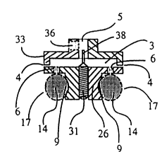
Figure 7 shows the flow limiter and the water jet regulator
diagrammatically. Figure 7 shows the assembly of casing 19,
coiled spring 17, throttle disc 34, straight round disc 25 and
throttle screw 27.
The water enters the distribution chamber 3 through holes 5 and
36 and flows through the holes of the straight round disc, while
air is getting sucked into the cavity of the coiled spring due to
the arrangements of the air-suction slits. The water, mixed with
air, exits via the coiled spring 17. Pre-throttling is done with
throttle disc 34 and the for its diameter selected inlet 5.
Fine- throttling is done with throttle screw 27.
Figure 8 shows in its section especially the throttle disc 34,
the straight round disc 24, the casing 19, and the coiled spring
17. Pre-throttling is done with the throttle disc 34 and fine-
throttling with throttle screw 30.
Figure 9 shows in its section especially the throttle disc 15,
the straight round disc 22, the coiled spring 17, the coiled
spring 7, the casting 19, and the throttle screw 28. Throttling
is done with the throttle disc 15 and the for its diameter
selected inlet.
The shape of the water jet outflow depends on the different
throttle screws or coiled springs (closed ring shaped helical
springs) that are used. The insertion of a second coiled spring
7 into the coiled spring 17 reduces the speed of the flow. If
the perforated disc 21 is fitted into the distribution chamber 3
with the throttle screw 27, 28 or 29, it will be constantly moved
by the water flowing through. This keeps the distribution
chamber free of dirt and lime deposits.

21~7881
List of Details and Parts
(1 ) Throttle body
(2 ) throttle screw, throttle body
(3 ) distribution chamber
(4 ) support edge
(5 ) inlet
(6 ) throughhole
(7 ) coiled spring within the coiled spring (17)
(8 ) gap under the perforated disc in lifted condition
( 9 ) yloove
(10) shoulder
(11) air suction slit
(12) inlet of the throttle disc (15)
(13) gap between the coiled springs (17) and (7)
(14) cavity
(15) throttle disc without throttle body
(16) throttle screw, rounded
(17) coiled spring
(18) throttle disc with throttle screw
(19) casing
(20) screwhead of the throttle screw (30)
(21) perforated disc
(22) straight round disc (stepped)
(23) straight round disc (stepped) with female thread
(24) straight round disc with countersink for the screwhead
(20) of the throttle screw (30)
(25) straight round disc with female threat
(26) straight round disc, grooved with female thread
(27) radius of the throttle screw (27)
(28) throttle screw with cone point (37)
(29) throttle screw, countersunk
(30) throttle screw with head
(31) throttle screw, needle pointed
(32) coiled spring, inside
(33) throttle disc with side-hole (36)
(34) throttle disc with through-hole (36)
(35) throttle disc without side-hole
(36) side-hole of the throttle disc (33)
(37) needle-point of the throttle screw (31)
(38) throttle screw cone-point of the throttle screw (31)
(39) holes of the perforated disc (21)
(40) straight rounded disc with female threat
(41) casing

Representative Drawing
A single figure which represents the drawing illustrating the invention.
Administrative Status

For a clearer understanding of the status of the application/patent presented on this page, the site Disclaimer , as well as the definitions for Patent , Administrative Status , Maintenance Fee  and Payment History  should be consulted.

Administrative Status

Title Date
Forecasted Issue Date Unavailable
(86) PCT Filing Date 1994-03-04
(87) PCT Publication Date 1994-09-15
(85) National Entry 1995-09-08
Examination Requested 1999-02-05
Dead Application 2003-03-04

Abandonment History

Abandonment Date Reason Reinstatement Date
2002-02-07 R30(2) - Failure to Respond
2002-03-04 FAILURE TO PAY APPLICATION MAINTENANCE FEE

Payment History

Fee Type Anniversary Year Due Date Amount Paid Paid Date
Application Fee $0.00 1995-09-08
Maintenance Fee - Application - New Act 2 1996-03-04 $50.00 1995-09-08
Maintenance Fee - Application - New Act 3 1997-03-04 $50.00 1997-03-04
Maintenance Fee - Application - New Act 4 1998-03-04 $50.00 1998-02-03
Request for Examination $200.00 1999-02-05
Maintenance Fee - Application - New Act 5 1999-03-04 $75.00 1999-02-05
Maintenance Fee - Application - New Act 6 2000-03-06 $75.00 2000-03-03
Maintenance Fee - Application - New Act 7 2001-03-05 $75.00 2001-02-28
Owners on Record

Note: Records showing the ownership history in alphabetical order.

Current Owners on Record
PRENZLER, KLAUS
Past Owners on Record
None
Past Owners that do not appear in the "Owners on Record" listing will appear in other documentation within the application.
Documents

To view selected files, please enter reCAPTCHA code :


To view images, click a link in the Document Description column. To download the documents, select one or more checkboxes in the first column and then click the "Download Selected in PDF format (Zip Archive)" or the "Download Selected as Single PDF" button.

List of published and non-published patent-specific documents on the CPD .

If you have any difficulty accessing content, you can call the Client Service Centre at 1-866-997-1936 or send them an e-mail at CIPO Client Service Centre.


Document
Description 
Date
(yyyy-mm-dd) 
Number of pages   Size of Image (KB) 
PCT Correspondence 2000-06-19 1 16
Representative Drawing 1998-07-14 1 7
Cover Page 1996-02-12 1 16
Abstract 1994-09-15 1 67
Description 1994-09-15 4 193
Claims 1994-09-15 2 63
Drawings 1994-09-15 2 105
Fees 1998-02-03 1 40
Prosecution-Amendment 1999-02-05 1 34
PCT 1995-09-08 25 891
Assignment 1995-09-08 6 207
Prosecution-Amendment 2001-08-07 2 78
Fees 1999-02-05 1 42
Fees 2000-03-03 1 37
Fees 2001-02-28 1 37
Fees 1997-03-04 1 52
Fees 1995-09-08 1 55