Note: Descriptions are shown in the official language in which they were submitted.
WO 94/22398 PCT/US94/01578
-1
PROSTHETIC DEVICE INCORPORATING LOW ANKLE DESIGN
Field of the Invention
The present invention relates to prosthetic devices, and
in particular, prosthetic devices incorporating a rigid shin
portion and a small radius or tight ankle section.
Background of the Invention
Many types of prosthetic devices have been developed over
the years. In the early years, emphasis was placed on
constructing an artificial limb which looked and moved much
like a human limb. For example, many prosthetic devices were
fabricated with a leg member and a foot member, with some form
of pivoting member therebetween near the ankle region to allow
the foot member to rotate about the ankle region. Elaborately
constructed prosthetic devices were introduced, each
attempting to simulate the natural movement of the human leg,
ankle and foot. Though each of these attempts were intended
to provide some level of normalcy to the artificial limb, they
lacked the resilient energetic response needed for non-
sedentary activities.
Various improvements have been made to prosthetic devices
to enable the amputee to substantially increase his or her
activity level. The advent of new materials, such as graphite
composite materials, which are lightweight, strong, durable
and relatively flexible, have been developed to further
improve the performance of prosthetic devices. Also, contrary
to earlier thinking, better compliance and energy response has
been obtained by simplifying the structure of the prosthetic
device rather than making it more complex. Prosthetic devices
incorporating simple curved, flat, spring-like members have
been developed which now enable amputees to participate in
strenuous activities, such as tennis, basketball and jogging.
In particular, a prosthetic foot and leg device allowing
a high degree of mobility on the part of an amputee was
disclosed in applicant's U.S. Patent No. 4,457,913 entitled
"COMPOSITE PROSTHETIC FOOT AND LEG." That patent discloses a
prosthetic foot and leg device utilizing a resin impregnated
high-strength filament structure for the leg portion, foot
x.158015
E
-2-
portion and heel portion, with all three regions being
provided with substantial elastic flexibility, of relatively
low energy absorption characteristics, so as to give the
wearer high mobility with a relatively natural feel. Contrary
to earlier prosthetic devices which incorporated a rotatable
or articulated ankle mechanism, this prosthetic device has no
moving parts other than the inherent flexibility and energy
response characteristics of the material itself.
That prosthetic device also has a substantially elastic
leg portion, wherein the flexibility of the leg portion is in
addition to the flexibility of the heel and foot portions.
Though this flexibility provides additional energy storage and
release, and gives the prosthesis increased resiliency and
energy response, this additional flexibility in the leg makes
the prosthesis somewhat springy, unlike the tibia and fibula
of the human limb which are not flexible and elastic.
In U.S. Patent No. 4,822,363, the applicant attempted to
provide some rigidity to the shin portion so that the flexure
would take place beneath the upper leg portion. However, as
with the prosthetic device of the above-referenced patent, the
flexibility and resiliency of the prosthetic device was built
into the entire lower leg region, including the shin, foot,
and heel portions, up to and including the bottom 25.4 cm
(10.0 in.) of the prosthetic device. It was thought that if
the flexibility in the lower leg region was eliminated to any
greater extent, the prosthesis would lose a valuable portion
of its capacity to store and release energy. with at least
25.4 cm (10.0 in.) of clearance between the lower extremity of
the rigid shin portion and the ground, the curvature of the
flexible shin and ankle regions was smooth and continuous, and
the resiliency and energy response characteristics of this
prior device was excellent, without stops or jolts during use.
Furthermore, from a structural point of view, the smooth
curvature of the shin and ankle regions could be adapted to
have a substantial radius, thereby avoiding any stress
concentrations in the prosthesis . Due to the gradual curve of
a relatively large radius (in some cases the curve was complex
AM~P?BEfl SH~~ f
WO 94/22398 ~ PCT/US94/01578
-3-
and not a simple curve), the space beneath the curve member
provided for a relatively long heel capable of demonstrating
good resiliency and flexibility.
Nevertheless, the energy response of such previous
devices was often too great for some patients, exceeding their
particular needs. With certain geriatric or youth patients,
the springiness of such prior devices was somewhat difficult
to manipulate or control, reducing stability. Thus, there
remains a need for a foot prosthesis which demonstrates good
performance capabilities under a wide range of physical
activities, but which at the same time provides enhanced
safety, security, and control for the wearer.
Summary of the Invention
The present invention represents a substantial
improvement over the prior art prosthetic devices in that the
high energy response characteristics are utilized in
conjunction with a relatively stiff leg or shin portion, a
lower bending axis and a tighter ankle section, which together
more closely function like the ankle region of a natural human
limb. Unlike the previous prosthetic devices, which flex
along a relatively long leg distance, the present invention
relates to a prosthetic device having an ankle section with a
relatively tight radius of curvature, which substantially
concentrates the bending in the ankle region to proximate the
bending of the human ankle. The smaller radius of curvature
also helps lower the flexing point, i.e., the axis of bending,
of the prosthetic device, to more closely match the location
of the human ankle region.
A lower axis of bending is an important advantage in the
present invention due to the trend in recent years regarding
the manner in which amputations are conducted. The medical
profession is now recognizing the advantage of performing
amputations lower to the ground, preserving a substantially
longer stump for the amputee than in the previous conditions.
This longer stump provides, in turn, a longer lever arm for
use in connection with the prosthesis, thereby permitting the
exertion of greater strength upon the prosthesis. This means
WO 94122398 ~ PCT/US94I01578
- -4-
that the prosthesis, if correctly engineered as in the present
invention, can return an extremely high percentage of energy
to the wearer in order to provide excellent performance;
0
however, at the same time, the performance characteristics of
S the prosthesis must be accomplished in a structure which is
provided with less distance from the ground to the stump.
Thus, with lower amputations, higher performance is possible,
but a greater risk of breakage due to stress concentrations
exists.
However, the prosthesis of the present invention takes
advantage of this tendency, while at the same time adequately
addressing the issues of strength and performance. Thus, the
present prosthesis can be used with excellent results by a
much wider diversity of amputees including those with lower
amputations. At the same time, stability and control are
achieved.
Unlike prior art devices which disclose a flexible leg
portion and a substantially large radius of curvature ankle
section, which results in a very high rate of energy return,
the present invention serves to relocate and confine the
bending. In other words, with prior devices, flexibility and
energy return were available in the upper leg regions of the
prosthesis. In the present invention, however, since the
upper leg region is substantially rigid, a portion of that
flexibility previously available has been relocated to a newly
designed ankle in which the flexibility is isolated or
concentrated. While some overall performance is thereby
sacrificed, greater prosthetic stability and control are
achieved with yet excellent performance characteristics. This
performance is also achieved through the design of cooperating
heel and toe sections which have optimal flexible lever arms,
as explained below in more detail. Thus, the flexibility of
the present heel section upon heel strike and that of the
present toe section at toe off, cooperate with the bending
concentrated in the ankle region to provide a high performance
prosthetic device.
WO 94122398 ~ PCT/US94/01578
-5-
In addition, in previous devices, a flexible leg portion
and a relatively large radius of curvature ankle section
caused the prosthesis to shift substantially in the fore and
aft direction when deflected and allowed twisting in the
torsional direction, which made the prosthetic device more
difficult to control. Not only did amputees have to adjust to
this difference, some amputees, such as geriatrics or
children, lacking sufficient strength, did not have the
ability to make that adjustment. The present invention
addresses this problem by providing a flexible ankle section
having a relatively small radius of curvature, whereby
horizontal deflection is minimized. This design allows the
present invention to exhibit good qualities for stability and
control.
The configuration of the present invention also enhances
stability and control by providing a substantially more
lifelike feel. Because the present invention utilizes a
substantially rigid pylon, and the bending previously
available from the upper leg region is concentrated primarily
in the ankle region, the additional springiness associated
with the flexible leg and shin portion is eliminated. Thus,
the present prosthesis flexes in the ankle region in a manner
that more closely resembles the movement of the natural human
limb, thereby giving the wearer better control and "feel."
More specifically, the present invention comprises a
substantially rigid tubular pylon member extending downward
from the stump of the amputee. Because the pylon member is
substantially rigid, it performs much like the tibia and
fibula of the human leg. In a preferred embodiment, the rigid
pylon member is tubular and hollow to impart less weight,
while providing rigidity against bending. Attached at the
lower end of the rigid pylon member is a flexible ankle
section which incorporates a simple curved, flat, spring-like
surface, which is similar to a leaf spring. The ankle section
extends downward from a vertically oriented upper section and
forward to a horizontally oriented lower toe section. The
WO 94/22398 PCT/US94/01578
_6_
curvature along the ankle section can be simple arc of a
circle or a complex configuration.
The cross-sectional shape of the ankle section is
preferably rectangular, although the edges do not necessarily
have to be rectilinear. In the preferred embodiment, the
width of the cross section of the ankle section is
substantially greater than its thickness. To permit
flexibility along a vertical plane in the fore and aft
direction, the moment of inertia of the ankle section is
relatively small about a horizontal axis perpendicular to the
fore and aft direction. To restrict bending in the other
planes, the ankle section has a high moment of inertia about
an axis generally aligned with the fore and aft direction.
Another important advantage of the present invention is
that it provides adjustability to the wearer with respect to
the energy return characteristics of the ankle. Since the
ankle is detachably mounted to the distal end of the rigid
pylon member, it can be interchanged with ankle sections of
similar design but which have different flex characteristics,
thereby allowing the wearer to achieve optimal performance in
connection with a wide variety of strenuous or less strenuous
physical activities. Likewise, the heel section is also
demountably attached to the underside of the ankle section to
permit adjustability in connection with the spring rate of
that element.
The substantially rigid pylon member is also
interchangeable, and can be cut and adapted to different
lengths. This advantageously permits the pylon member to be
removed and adjusted to suit the particular size of an amputee
or can accommodate a growing amputee. This permits the
remainder of the prosthesis to be produced in standard sizes,
while permitting pylon members to be cut and fit to the
particular needs of an amputee. Applicant's invention permits
prosthetists to cut a standard tubular or other relatively
stiff pylon to an appropriate length, eliminating the risk
that the more expensive prosthesis having an integral leg
section might inadvertently be cut too short. This also
_ 2~5so~5
reduces the amount of material needed to produce the
prosthesis, eliminates the waste attributed to cutting
the extra length of leg section, makes the prosthesis
lighter, and substantially lowers the cost.
Accordingly, in one aspect of the invention, there is
provided a prosthetic foot for providing resilient
kinematic support to an amputee relative to a ground
surface. The prosthetic foot comprises an upper section
which includes mounting means for securing to a pylon or
socket; a resilient curved ankle section which extends
downwardly and forwardly from the upper section and which
has a defined radius of curvature of less than about 7.6
cm (3.0 inches) about a bending axis about which a
substantial amount of bending occurs, the bending axis
being located at or about the location of a normal human
ankle joint; a toe section formed integrally with and
extending forwardly and substantially horizontally from
the ankle section whereby as a vertically upwardly
directed force is placed on the toe section, the
resultant horizontal deflection of the tip of the toe
section is less than one-third of the resultant upward
deflection of the tip of the toe section; and a heel
section extending rearwardly from the ankle section.
In summary, the present prosthetic provides good
performance characteristics while enhancing stability and
control for the wearer. In addition, the prosthesis, due
to its simple design, can be inexpensively manufactured
as compared to previous prosthesis.
Brief Description of the Drawin s
FIGURE 1 is a perspective view showing the prosthetic
device of the present invention with a pylon connected;
FIGURE 2 is a prosthetic device similar to FIGURE l,
without a pylon;
FIGURE 3 is a side elevational view of the prosthetic
device of FIGURE 1;
x~..' _~_~..,_._...v~..~.~:.__.._.~w.._...~..~.__.._.~..~.~..~.
~...,.u___.~...~.._...~ _
2158015
-7a-
FIGURE 4 is a top plan view of the prosthetic device
of FIGURE 1;
FIGURE 5 is a front elevational view of the
prosthetic device of FIGURE 1, with a portion of the
middle ankle section middle removed;
FIGURE 6 is a schematic diagram showing the flexing
and movement of a prior art prosthetic device;
FIGURE 7 is a schematic diagram showing the flexing
and movement of the prosthetic device of the present
invention;
FIGURE 8a is a schematic showing an idealized
representation of a prosthetic ankle having a load
applied upwardly at the toe region;
FIGURE 8b is a schematic drawing of the curvilinear
section of the ankle showing the applied forces and
moments;
FIGURE 8c is a schematic drawing of the ankle section
showing the resultant horizontal deflection 0x.
FIGURE 9a is a chart showing horizontal and vertical
deflections of the present invention and a prior device.
FIGURE 9b is a schematic drawing showing the set up
of the test shown in FIGURE 9a.
Description of the Preferred Embodiments
30
WO 94/22398 PCTIUS94/01578
2158015
_8_
The present invention relates to a prosthetic device
utilizing a relatively stiff leg or shin portion and a
substantially small radius ankle section, which together serve
to confine the point of bending to more closely simulate the
dorsiflexion and plantarflexion of the natural human foot at
the ankle joint. It should be noted that when the term
"radius" or "radius of curvature" is used herein, it is not
intended to be limited to a simple arc or curve, but is
intended that complex curves are also within the scope of the
present invention. For convenience, these terms are used to
simplify the description; however, one of ordinary skill in
the art will understand that non-simple curves are equally
feasible.
In particular, the present invention has a relatively
stiff shin portion, in combination with a flexible ankle
section having a tight radius of curvature, which helps lower
the flexing point of the prosthetic device. This combination
also isolates the point of bending so that the bending axis is
more closely in line with the center line of the load on the
prosthetic device.
Construction of the Prosthesis
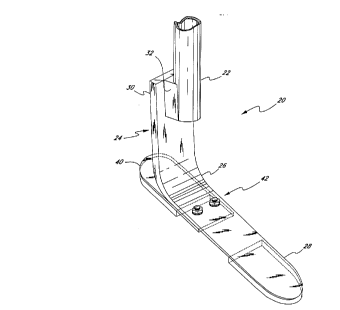
As can be seen in FIGURE 1, the prosthesis 20 of the
present invention has a pylon member 22 which can be secured
to the stump of the amputee (not shown) and extends relatively
downward therefrom in a generally vertical direction. The
pylon member 22 in the preferred embodiment is of tubular
construction, having an equal moment of inertia in all
directions to restrict bending in all directions. The tubular
member 22 is also hollow so that it is relatively light in
weight, and utilizes less material, which reduces the cost of
production, and preferably has the dimensions of standard
tubular pylons.
Other configurations which impart rigidity, such as
rectilinear cross sections having relatively larger moments of
inertia, can also be utilized to obtain the benefits discussed
herein. Stiffness in the pylon member 22 can also be provided
by a stiffer and more dense material.
WO 94/22398 PCT/US94101578
_g_
The tubular pylon member 22 can also be removed from the
prosthetic device, such that the pylon member can be replaced
without replacing the remainder of the prosthetic device.
This permits applicant' s invention to be utilized in a broader
range of applications.
For instance, the tubular member 22 of applicant's
invention can be cut and adapted for use by amputees having
different stump lengths, including growing amputees. The
prosthetist merely needs to cut a standard tubular pylon to
the appropriate length. Moreover, this eliminates the need to
manufacture, as a part of the prosthesis, a long rigid leg
section. Thus, fewer materials are needed to manufacture the
prosthesis of applicant's invention, resulting in reduced
manufacturing costs.
As shown in FIGURE 1, a foot portion 24 is secured to the
pylon member 22 such that the foot portion extends downward
therefrom. In the preferred embodiment, the foot portion 24
is comprised of an elongated member having a relatively flat,
curved surface and a rectilinear cross section made of
substantially flexible and durable material. Also, the foot
portion 24 can be made of non-rectilinear cross-sections to
achieve the same benefits discussed herein. As can be seen in
FIGURE 1, the foot portion 24 in the preferred embodiment
extends generally vertically downward from the pylon member
22, bending about an ankle region 26 and extending to a toe
section 28.
In the preferred embodiment, the thickness of the foot
portion 24 is a small fraction of its width, whereby the
moment of inertia about a horizontal axis perpendicular to the
fore and aft direction is substantially smaller than the
moment of inertia about a horizontal axis generally in the
fore and aft direction. This configuration permits bending in
a vertical plane in the fore and aft direction, while
restricting bending about other planes. The configuration
also helps to control torsional movement by allowing some, but
prohibiting excessive, movement.
2158015
-10-
With reference to FIGURES 1, 3 and 4, the upper section 30
of the foot portion is, in the preferred embodiment,
vertically oriented so that it may be secured to the pylon
member 22, as seen in FIGURE 1. As shown in FIGURE 3, an
attachment device 32 is positioned at the lower end of the
pylon member 22, which provides a flat surface upon which the
vertical section 30 of the foot portion 24 can be secured.
The attachment device has one attachment surface 34 which
mates with the outside surface of the pylon member 22, and a
second attachment surface 36 which mates with the foot portion
24. In the preferred embodiment, one attachment surface 34 of
the attachment device is curved to mate with the outside
surface of the tubular pylon member 22, and the second
attachment surface 36 is flat to accommodate the flat upper
section of the foot portion.
Desirably, the attachment device 32 is welded to the pylon
member 22 and has two holes (not shown) into which two bolts
38 can be inserted and secured. The upper section 30 of the
foot portion 24 also has two holes (not shown) which align
with the two holes on the attachment device 32, such that by
placing and securing two bolts 38 through the foot portion and
the attachment device, the foot portion can be secured to the
lower end of the pylon member. Other methods of securing the
pylon member to the foot portion are clearly contemplated.
As shown in FIGURE 3, the ankle portion 26 is demountably
attached to the pylon 22 by means of fasteners 38 and
demountably attached to the heel 40 at the forward connection
42 by means of fasteners 41. Thus, as noted above, the ankle
portion 26, as well as the heel portion 40, are
interchangeable with other similar portions in order to
achieve prosthetic adjustability.
As stated, the upper section 30 of the foot portion 24 is
vertically aligned so that it extends relatively downward from
the attachment device 32 on the pylon member 22. As shown in
2158015
FIGURE 3, thickness of the foot portion 24 along this vertical
section is relatively greater than the thickness of the foot
portion along the toe section 28. This thickness provides
sufficient rigidity to the connection between the pylon member
22 and the foot portion 24. This upper section 30 is also
made relatively thicker to support the vertical load imposed
on the prosthetic device 20, as well as restrict undue bending
at this juncture. The entire upper vertically aligned section
30 is of uniform thickness and width.
In the preferred embodiment, as shown in FIGURE 4, the
foot portion 24 is a su~stantially constant width from the
upper rigid portion 30 down to the toe section 28, with the
toe end 46 being rounded to accommodate various cosmesis which
simulate an actual foot. Desirably, the foot portion 24 has
a width of between 3.8 and 7.6 cm (1.5 and 3 in.), and the
width is preferably about 5.1 cm (2 in.). Of course, one of
ordinary skill will immediately recognize that prosthetic feet
having different dimensions and parameters can achieve the
advantages of the present invention, and that the dimensions
and parameters provided herein are merely only one example of
an embodiment of the present invention.
Referring again to FIGURE 3, attached to the foot portion
24 is a heel portion 40, which is secured to the underside of
the foot portion 24 between the ankle region 26 and the toe
section 28. The heel portion 40 is also relatively flat,
although it can be curved. It also has a rectilinear cross
section in the preferred embodiment, although in other
embodiments the cross section does not necessarily have to be
rectilinear. The heel portion 40 is also made of the same
flexible and durable material as the foot portion 24, as will
be discussed, and has a thickness which is a small fraction of
its width. Thus, its bending characteristics are similar to
the bending characteristics of the ankle section.
The heel portion 40 extends rearward from a forward
connection 42 with the foot portion 24, and has a length, in
the preferred embodiment, which is greater than its width.
The configuration of the heel portion 40 is designed to be
~~ rc~.srF(1 SHr ~ ~
WO 94/22398 PCT/US94/01578
._
-12-
relatively flexible about an axis parallel to its width, while
being resistant to flexing about an axis parallel to its
length and about an axis normal to the surface of the heel
portion.
In order to provide a uniform walking surface on the
underside of the prosthetic device 20, one or two separate
sole members 44a and 44b are included in the present
invention, as shown in FIGURE 3. A front sole member 44a is
adhesively attached to the underside of the toe section 28 of
the foot portion 24, and a rear sole member 44b is adhered to
the underside of the heel portion 40. The sole members 44a,b
may be constructed from a similar material as the foot and
heel portions 24, 40, or may be manufactured from a more
pliant material such as urethane or a hardened rubber.
The present invention is made of a resin impregnated,
high strength material, such as graphite composite, or a
filament structure, arranged in laminates. Excellent results
have been obtained using carbon filament with an epoxy binder,
such as those disclosed in my previous U.S. patents, Patent
Nos. 4, 547, 913 and 4, 822, 363 . In particular, the foot portion
24 and heel portions 40 of the present invention are made of
a resin impregnated, high strength material having
substantially elastic flexibility so as to impart relatively
low energy absorption to give the wearer high mobility and a
relatively natural feel.
The rigid pylon member 22 can also be made of the same
material. The pylon member's rigidity, however, is provided
predominantly by its tubular shape. But because the material
has some elastic flexibility, in spite of the tubular shape,
the pylon member 22 has some nominal flexibility. The
components of the present invention, however, are not limited
to construction from such a material, but rather can be made
of materials with such characteristics.
The present invention can also be integrally formed,
rather than modularly formed, although in the preferred
embodiment, the pylon member 22 is removable from the foot
portion 24, and the heel portion 40 is removable from the foot
z~~~o~~
-13-
portion. This modularity is provided by a nut-and-bolt
construction.
Curvature of the Ankle Section
To impart the benefits of the present invention, and to
isolate the bending of the foot portion 24, thereby
proximating the dorsiflexion and plantarflexion of the human
ankle region, the foot portion is provided with a tightly
curved ankle section 26, curving downward and forward to the
toe section 28 which is at approximately a 90o angle with the
vertically aligned upper section 30. The radius of curvature
"r" (shown in FIGURE 3) at this ankle section 26 is, in the
preferred embodiment, approximately 5.1 cm (2 in.), with a
desirable range being between 1.3 to 7.6 cm (0.5 to 3 in.).
Though in the preferred embodiment this curvature follows'a
simple arc having a relatively constant radius, the curvature
can also follow a complex arc having a varying radius of
curvature. This tight radius of curvature, in conjunction
with the relatively stiff pylon member 22 and the relatively
thick upper section 30 of the foot portion 24, locates the
axis of bending lower to the ground and more closely resembles
the position of the human ankle region. In addition, as noted
above, a lower axis of bending permits the present prosthesis
to be mounted on a longer stump, as exhibited by the present
trend toward lower amputations. Although this configuration
concentrates the flexibility and corresponding bending
stresses in the ankle region 26, the present ankle has been
designed, as explained below in more detail in connection with
Table 1, so as to return good performance characteristics
while adequately resisting such bending stresses.
In the preferred embodiment, the foot portion .24 is
secured to the back side of the pylon member 22, as can.be
seen in FIGURE 3. This off-center alignment advantageously
helps to position the axis of bending closer in line with the
center line of any vertical loads imposed on the prosthetic
device. This tends to reduce moment forces when the foot is
subjected to such vertical loads, and further reduces any
horizontal deflection when the toe is subjected to vertical
r,~~
nr?!,EViC~t~ ~n _~
WO 94/22398 ~ ~ PCT/US94/01578
-14-
loads, as explained below in more detail. This off-center
rearward alignment also increases the toe lever arm to provide
additional leverage, which assists in providing flex balance.
As can be seen in FIGURE 3, the radius of curvature "r" of theJ
ankle section 26 has a center axis which is substantially
below the lower end 22a of the pylon member 22, and therefore
closer in line with the vertical centerline of the pylon.
This configuration lowers and isolates the bending of the
foot portion 24, while permitting additional flexibility and
energy storage and release in the foot portion. A longer foot
portion tends to be more flexible and therefore provide more
energy storage and release. By connecting the foot portion 24
on the back side of the pylon member 22, the foot portion
extends upward above the lowest extremity 22a of the pylon
member, imparting additional flexibility while still confining
and lowering the bending axis.
By attaching the foot portion 24 to the back side of the
pylon member 22, the lever arm of the toe section 28 is
extended, thereby providing additional toe flexibility and
foot portion leverage. The foot portion 24 extends downward
from the back side of the pylon 22 and extends forward,
thereby providing a greater moment arm relative to the bending
axis of the ankle section 26. This additional leverage
provides the amputee with better control during the toe off
phase of a normal stride . Though the foot portion 24 can also
be attached to the front side of a pylon member, the lever arm
of the toe section 28 would be reduced, thereby permitting
less resiliency and energy response in the forward section of
the prosthesis.
It should be noted that many parameters must be
considered in designing a high performing foot prosthesis of
this type. The principal design parameters are: (1) the
point of attachment of the prosthesis to a relatively rigid
upper pylon; (2) the flex characteristics of the ankle member,
as determined primarily by its radius of curvature and
thickness; (3) the toe length and flex characteristics of the
toe member; and (4) the heel length and flex characteristics
~.~5~~1~
-15-
of the heel member. Other factors, such as overall weight and
cosmetic compatibility, must be considered, but these are the
more important performance parameters.
In addition, it will be readily recognized that these
parameters represent a number of compromises or tradeoffs.
For example, as noted herein, if the point of attachment of
the foot prosthesis is relatively low, the ankle section of
the present design exhibits a relatively tight radius, thus
restricting maximum energy response. The ankle, however,
exhibits good energy response with some restricted vertical
deflection (or reduced "springiness" as cescribed herein),
providing greater control and stability. At the same time,
the curvature of the ankle must be thickened, as explained
below in more detail, to accommodate the concentration of
bending stresses therein. In addition, the curvature of the
ankle must provide sufficient clearance from the ground to
accommodate a heel of adequate length. Thus, a number of
tradeoffs have been considered in arriving at the optimal
design of the present invention.
The ankle design of the present invention also permits an
optimal toe and heel configuration to cooperate in the overall
performance of the foot prosthesis. In one particular
example, a prosthesis manufactured in accordance with the
present invention and having a radius of curvature "r" of
about 5.1 cm (2 in.) cooperated with a toe lever arm as
measured from the forward point of attachment 42 to the tip of
the toe 46 of about 11.4 cm (4.5 in.), while the cooperating
heel lever arm from the same point of attachment to the distal
tip of the heel 40 is about 11.4 cm (4.5 in.). Although many
other prostheses of different dimensions are within the scope
of the present invention, it is believed that the present
invention provides optimization of performance characteristics
with safety and low cost.
Though the preferred embodiment has a separate foot
portion 24 secured to a separate pylon member 22, the present
invention also contemplates a foot portion that is an integral
extension of the pylon member, such that the axis of the pylon
pl.,c;,~G~~ SH~~T
~i5~fl~~
-16-
member is in line with the axis of the upper section 30 of the
foot portion. Though some prior devices have a similar
configuration, wherein a flexible foot portion extends
downward from a rigid upper section, none of the prior devices
particularly disclose the tight radius of curvature ankle
section 26 and the low bending axis described herein.
In the preferred embodiment, the pylon member 22 has a
lower extremity 22a which extends to about 8.9 cm (3.5 in.)
from the bottom of the sole members 44a,b. Though this
distance-"h", as shown in FIG. 3, can be adj~isted to
accommodate various amputee preferences, including size,
weight, resiliency, springiness, flexibility and activity
level, the advantages discussed herein are readily obtained if
the lower extremity 22a of the pylon member 22 extends no more
than about 12.7 cm (5 in.) and no less than about 6.4 cm (2.5
in.) from the bottom of the sole members 44a,b, with a range
between 6.4 to 12.7 cm (2.5 to 5 in.).
The exact location of the pylon member 22 with respect to
the foot portion 24 is determined by a combination of factors,
including the length, thickness and curvature of the foot
portion. The closer the lower extremity of the pylon 22 is to
the bottom of the sole members 44a,b, the tighter the radius
of curvature of the ankle section 26 must be. Concurrently,
the tighter the radius, the thicker the ankle section 26 must
be because stress concentrations become more isolated. Even
though the increased thickness of the ankle section 26 causes
it to become more rigid, substantial flexibility of the ankle
section can still be achieved by a high performance ankle
section.
Because the thickness of the ankle section 26 slightly
lowers the resiliency and energy response provided by the
prosthetic device 20, the present invention is well adapted
for use by those who are moderately active and who are willing
to sacrifice a small degree of maximum performance in exchange
for greater stability and control. In addition, because the
prosthetic device 20 achieves a movement and performance that
~~"~'~,C~fl SN~~;
WO 94/22398 _ 215 8 0 i 5 PCT/US94101578
-17-
resembles a human limb, it is ideal for active use, such as in
running, jogging and jumping.
Concentration of Bendina at the Ankle Section and Reduction of
Horizontal Deflection ~ -
One advantage of the present invention is the manner in
which the prosthesis bends or deflects. FIGURES 6 and 7
provide a comparison of the way the prosthesis of the prior
art bends with respect to the way the prosthesis of the
present invention bends. As can be readily seen, the
prosthesis of the prior art has a wide range of movement
through the length of the flexible prosthetic leg and ankle
member. The bending, and therefore deflection, occurs along
the entire length of the flexible member. On the other hand,
the flexible member of the present invention tends to
concentrate bending near the curved ankle section 26, although
in a normal gait, additional deflection will occur along the
toe section 28. FIGURES 6 and 7 are intended to show the
deflection of the curved portion of the flexing member, i.e.,
the ankle section.
An important aspect of the present invention is the
concentration of bending, which is accomplished by reducing
the radius of curvature of the ankle section 26. With
previous devices, a relatively long flexing member was
provided so that greater amounts of energy could be stored
along the length of the flexing member. The goal was to
obtain as much performance from the bending and deflection
which occur throughout the length of the flexing member.
However, prior devices having relatively long flexing
members, and large radius ankle sections, tended to be overly
springy, deflecting substantially in the fore and aft
direction. Indeed, one of the important benefits of the
present invention is a reduction in the horizontal movement
caused by the flexing of the ankle section.
As can be shown mathematically, a curved member having a
certain radius of curvature deflects both vertically and
horizontally when a vertical load is placed at the end of the
curved member. For instance, as an upward force is directed
WO 94/22398 ~ 1 PCT/US94/01578
-18-
at the toe end of the curved member, as schematically shown in
FIGURES 8a-c, the toe member will deflect upward, causing a
corresponding horizontal deflection in the forward direction
0x. As can be seen in FIGURE 8c, there is both a vertical
deflection component and a horizontal deflection component,
fix, which results from an upward force directed at the toe end
of the curved member.
Though schematically the vertical deflection results in
a forward horizontal deflection component, shown as Ox in
FIGURE 8c, in actual practice this forward horizontal
deflection results in a rearward horizontal movement relative
to point P. In other words, when an amputee places a load on
the toe section 28, the toe section becomes planted and the
back end of the prosthesis, rather than the toe section,
moves. As a result, when an amputee places weight at the toe
end of the prosthesis, the horizontal deflection component is
backward relative to the toe plant, rather than forward. In
practical terms, what this means is that with every step
taken, as the amputee plants the toe to push off, the toe
section deflects upward, causing a corresponding horizontal
deflection component which moves the prosthesis, and therefore
the amputee, backward relative to the toe plant. As will be
discussed, this rearward horizontal movement can cause the
amputee to lose his or her balance, and make it difficult to
control the prosthesis.
Thus, an important aspect of the present invention is the
reduction in this horizontal movement or deflection component
in the fore and aft direction as the amputee plants the toe.
The prosthetic device 20 of the present invention reduces this
horizontal deflection component, thereby serving to stabilize
the amputee and provide a more natural feel. By reducing the
backward movement of the prosthesis with every step taken, the
amputee will not experience the destabilizing springiness
associated with some prior prosthetic devices having large
ankle radius sections.
It is important to note here that for active amputees, a
large radius ankle section may be more desirable due to its
WO 94/22398 _ PCT/US94/01578
-19-
ability to store additional energy and provide a better energy
response. However, in view of the fact that many amputees are
not generally very active, a prosthesis having improved
control performance may be more desirable. Th~ZS, the present
invention represents a substantial improvement in the area of
prosthetic devices to provide the amputee with increased
control, which will help the amputee build confidence in the
prosthetic device, resulting in improved adaptability and
recovery.
This reduction in the horizontal deflection component,
which can be provided by reducing the radius of curvature of
the ankle section, can be shown mathematically. Test results
will also show a dramatic difference in the amount of
horizontal deflection caused by prosthetic devices having
ankle sections of varying radii of curvature.
First of all, the amount of horizontal deflection caused
relative to vertical deflection can be computed
mathematically. Referring to FIGURE 8a, an experimental ankle
loading situation is schematically shown. A leg member 50
having an upper substantially vertical section 52, an
intermediate curvilinear section 54 and a lower substantially
horizontal section 56 is fixed at a point 58 at an upper end.
An upward force F is applied at the toe end of the leg 50 at
point T to simulate a toe push-off of the leg in normal
walking or running. Assuming that the upper portion 52 is a
substantially rigid member resistant to bending, FIGURE 8b is
a force/moment diagram for the curvilinear section 54. The
upper end will be designated as fixed, as the upper portion 52
is substantially rigid. The lower end at point P will
experience an upward force F (or a shear force V in FIGURE 8b)
and a moment M equaling the force F times the distance L minus
r, which is the distance of 56 from the bottom end of the
curvilinear section 54 to the application of force F.
From the reference "Formulas for Stress and Strain, " R.J.
Roark, 4th Ed., p. 180, the following formula is obtained to
determine the amount of horizontal deflection relative to
2~~8Q1~
-20-
vertical deflection caused along the curved ankle section 54
by the upward force F:
~X= ~I [1~2z (1-BsinBcosB) +VR3 ( 2 -cosB+BsinBcos9+ cos28 -Sin~B) ]
2
oX - Movement in the horizontal direction of the Point
P in FIGURES 8b and 8c
E - Modulus of Elasticity
I - Moment of Inertia
M - Applied Moment
V - Vertical Shear Load
R - Radius
B - Included Angle of Radius in Radians
Example 1
For a prosthetic device of the present invention having
a 5.1 cm (2.0 in.) radius ankle section and a 0.61 cm (0.24
in.) constant
thickness:
E = 0.138 E6 MPa = 13.8 E6 N/cm2 (20 E6 lb/in2)
t = 0.61 cm (0.24 in)
I = bh3/12 = (5.1 (0.61) 3) /12 = 0.096 cm (0.
0023 in)
R = 5. 1 cm (2. 0 in. )
B = 1.5708 radians
sin B - 1
cos B = 0
L = 20.3 cm (8.0 in.)
Given that which
the applied
load F
= 67.9
kg (150
lbm),
is an average shear
weight
of an
amputee,
then the
vertical
load V 666 N (150 lbf) and the applied moment M = (0.203
= 666
- 0.051) - 101.5 N-m (900 in-lbf)
~X' 13 . SE6 ( . 096 ) ~ (-10150) (5. 1) ~ (1-1 . 5708 (1) -0) + (-666 ) (5 .
1) j ( . 5-0+0+0-12) ]
~Xl = 0.15 cm (0.058 in.)
This is the horizontal deflection at point P caused by
vertical load F. Because the toe section 56 is horizontal,
c ~::
LF': ,i(;~ ,:,
~~5~~~5
-21-
little or no additional horizontal deflection will occur along
the length of the toe section between point P and point T.
Further, because the horizontal toe section 56 extends beyond
point P, vertical deflection at point T will be greater,
although the horizontal deflection will remain virtually
unchanged. Thus, the relative horizontal deflection of the
prosthesis caused by a vertically upward force is
approximately 0.15 cm (0.058 in.). What this means is that
with every step taken, the prosthetic device will move
backward a distance of 0.15 cm (0.058 in.) with every 67.9 kg
(150 lbm) load placed on the toe.
Example 2
For a prosthetic device of the prior art having a 12.7 cm
(5 in.) radius ankle section, as shown in FIGURE 6, and 0.61
cm (0.24 in.) constant thickness:
E = 0.138 E6 MPa = 13.8 E6 N/cmz (20 E6 lb/in2)
t = 0.61 cm (0.24 in.)
I = bh3/12 = (5.1 (0.61) 3) /12 = 0.096 cm4 (0. 0023 in')
R = 12. 7 cm (5 in. )
B = 1.5708 radians
sin 8 = 1
cos B = 0
F = 666 N (150 lbf)
M = 666 (0.203 - 0.051) - 50.75 N-m (450 in-lbf)
~Xz= 6 [(-5075)(12.7)Z(1-1.5708(1)-0)+(-666)(12.7)3(.5-0+0+0-12)]
13.8E (.096)
~XZ = 0.87 cm (0.343 in.)
This is the horizontal deflection at point P caused by
vertical load F. Again, little or no further horizontal
deflection will occur along the horizontal toe section 56.
Thus, 0.87 cm (0.343 in.) represents the amount of horizontal
deflection caused by a 67.9 kg (150 lbm) load placed on the
toe section of the prosthesis. What this means is that with
every step taken, the amputee will experience a counteracting
~r
y.~.~v.;!~t~_' .'-.!i~~
._ 218015
-22-
backward movement of approximately 0.87 cm (0.34 in.) as the
amputee plants the toe of the prosthesis.
The results of these examples clearly show that the
smaller radius ankle section of the present invention will
result in much less horizontal deflection than the larger
radius ankle sections of the prior devices. Indeed, comparing
a 5.1 cm (2 in.) radius with a 12.7 cm (5 in.) radius shows
that the 12.7 cm (5 in.) radius ankle section experiences
approximately six times greater horizontal deflection than a
5.1 cm (2 in.) radius ankle section. This clearly shows that
the present invention not only concentrates bending in the
ankle section, but also prevents undesirable horizontal
deflection which will cause the amputee to feel as though the
prosthetic device were shifting slightly backward with each
step. The present invention minimizes this horizontal
deflection, which helps the amputee maintain greater control
and stability during utilization of the prosthetic device.
The results of the foregoing examples are also based on
ankle sections of constant thickness. The tapered ankle
section 26 of the present invention would in fact further
decrease the amount of horizontal deflection experienced.
This is due to the fact that the more flexible lower portion,
as will be discussed, of the ankle section 26 will experience
more of the bending as opposed to further up on the ankle
section. Thus, as the bending is concentrated lower in the
ankle portion by the tapered construction, the horizontal
movement will,correspondingly decrease.
A test was also conducted on a prototype of the present
invention and on a prior device having approximately a 12.7 cm
(5 in.) radius ankle section to determine the actual vertical
and horizontal deflections experienced at a point E, as shown
in FIGURES 9a and b. The devices were tested under a standard
loading machine with the upper end fixedly mounted. The load
was imposed in an upward direction at point E positioned about
15.2 cm (6 in. ) horizontally from the vertical position of the
ankle member. The upward force F corresponded to a reaction
force caused by a load up to and including a 67.9 kg (150 lbm)
placed on the device by an amputee. This upward load was
~_;,~.,r~~ ~HEET
215015
-23-
connected to a roller to permit horizontal movement at point
E as the upward force was applied.
FIGURE 9a charts the amount of deflection both
horizontally and vertically from 0 load to 67.9 kg (150 lbm)
load. The results of the experiment were fairly dramatic.
The amount of vertical and horizontal deflection of the
present invention is shown in the solid lines, and the amount
of vertical and horizontal deflection of the prior device is
shown in the dashed lines. The vertical deflection of the
present invention, given a 67.9 kg (150 lbm) load at point E,
was approximately 2.3 cm (0.9 in.), while the amount of
horizontal deflection caused by the same load was only
approximately 0.5 cm (0.2 in.). On the other hand, the
vertical and horizontal deflection caused by a 67.9 kg (150
lbm) load applied at point E on the prior device was
significantly greater. The amount of vertical deflection,
represented by a dashed line in FIGURE 9a, was approximately
4.3 cm (1.7 in.), while the horizontal deflection was
approximately 1.9 cm (0.75 in.). These results show that the
prior device moves horizontally almost as much as the present
invention moves vertically, given a 67.9 kg (150 lbm) load.
This difference can also be described in terms of ~a ratio
between the horizontal deflection and the vertical deflection.
Given a 67.9 kg (150 lbm) load the ratio of horizontal
deflection to vertical deflection of the present invention is
a fraction of 0.5/2.3 (.2/.9) or .22. The ratio of horizontal
deflection to vertical deflection experienced by the prior
device is a fraction of 1.9/4.3 (.75/1.7), which is
approximately .44. This ratio is significant when considering
that with every step taken, the vertical deflection of the toe
section will result in a corresponding rearward horizontal
deflection amounting to some fraction of the vertical
deflection. Given a .44 ratio, the prosthetic device will
move backward horizontally approximately 1.1 cm (.44 in.) with
every cm (inch) of vertical deflection experienced. Converse-
ly, in the present invention, the amount of horizontal
rearward deflection will be only approximately 0.56 cm (.22
in.) with every cm (inch) of vertical deflection experienced.
~;~~~.~r.~~ ~~i~El
f-
215815
-24-
Several factors contribute to this improvement in the
ratio of horizontal deflection relative to vertical
deflection. As is known in the art, and as can be shown
mathematically, the ratio of horizontal deflection to vertical
deflection at point P, as shown in FIGURE 8c, will be nearly
a constant ratio of approximately .59. Of course, this
depends on whether the curve follows a single radius arc, and
whether the curve extends along a 90o angle of radius in
radians. What causes the ratio of horizontal deflection to
vertical deflection to decrease is a function of how tight the
radius of curvature of the ankle section is and how long the
toe section 56 extends forward from the ankle section.
Because the horizontal toe section 56 will experience little
or no horizontal deflection as vertical deflection increases,
a longer toe section 56 will allow additional vertical
deflection without increasing horizontal deflection. By
decreasing the radius of curvature of the ankle section, a
longer toe section 56 can be extended from the bottom of the
ankle section, resulting in the capacity to permit additional
vertical deflection without increasing associated horizontal
deflection. This phenomenon significantly decreases the ratio
between the horizontal deflection and vertical deflection as
loads increase.
Preferably, in the present invention, the horizontal
deflection ~X is no more than 0.64 cm (0.25 in. ) , given a 67. 9
kg (150 lbm) load at point E, although up to 1.3 cm (0.5 in.)
would be permissible. Also, preferably, the ratio of
horizontal deflection to vertical deflection at point E (or T)
is less than one-third, although a ratio of up to .5 would be
acceptable. As discussed, this ratio is nearly constant (.59)
at point P, see FIGURE 8a, whether the ankle section radius is
large or small. However, the ratio at point T varies
depending on how small the radius is and how long the toe
section 56 is. With a small radius ankle section, the
resultant toe section 56 will be longer, resulting in greater
vertical deflection at point T without necessarily increasing
horizontal deflection. The ratio will also vary depending on
whether the thickness is
y~f..~c,~~,w c
:.
21~~~15
-25-
tapered along the ankle and toe sections . The thinner the toe
section 56, the greater the vertical deflection at point T
will be, and consequently, the greater the energy storage will
be, without increasing horizontal deflection along the ankle
section.
Taper of the Ankle Section. Heel and Toe
As seen in FIGURE 3, the foot portion 24 ha_ X tapered
thickness, the taper being a function of the flex__bility in
the foot portion. Though the upper vertical section 30 is
substantially uniform in thickness, the ankle section 26 has
a thickness which is tapered from the upper part "a" through
the middle part "b" to the lower part "c" of the
section.
Preferably, a series of standard thicknesses are provided
for amputees of varying sizes. For example, the prosthetic
device 20 of the present invention may be provided in nine
sizes with the designation "A1" through "A9," "A1" being the
thinnest for the smallest amputee and "A9" being the thickest
for a larger amputee. The following Table 1 gives th --ps
"t" at points "a," "b" and "c," corresponding to t._
middle and lower portions of the ankle portion 26 for the ~__
size categories. Furthermore, Table 1 provides the area
moment of inertia "I" about the bending axis for the points
"a, " "b" and "c" based on a foot portion 24 width of 5. 1 cm (2
in.)
Table 1. Tapered Ankle Section Thickness and
Moment of Inertia
t cm t~ t. I cm I~ 100(Ib/,.I. lOD(Ic/
cm cm cm' ) cm )
A1 .787 635 551 208 108 52.0 .07D8 34.0
3 0 AZ .815 .663 .574 229 123 53.7 .0799 34.8
A3 .848 683 592 .258 .135 52.2 0878 34.0
A4 881 706 612 290 149 51.4 0970 33.4
A5 .927 742 643 337 173 51.2 .112 33.3
A6 980 .760 676 .399 201 50.3 131 32 7
3 5 A7 1.03 818 70b 455 231 49.6 .149 32.0
A8 1.09 859 742 545 268 49 173 31.7
2
A9 1.14 890 775 629 305 _ 197 31.3
~ _
48.5
;,~~r~, - f
r,.. c,~:~El: ,. >
WO 94/22398 PCT/US94/01578
~1~8 ~D~.S
- -26-
As can be seen from Table 1, the thickness at the lower
point "c" of the ankle section 26 is approximately 70% of the
thickness at the upper part "a" for the sizes "A1" through
"A9 . " Due to the area moment of inertia being proportional to
the cube of the thickness at any one point, however, the area
moment of inertia of I~ in the lower region of the ankle 26 is
between 31% and 35% of the area moment of inertia Ia. Also,
the area moment of inertia Ib at the middle section is between
48o and 54% of the area moment of inertia Ia at the upper
region "a." Due to the fact that the amount of deflection
from a particular applied force is inversely proportional to
the area moment of inertia, a majority of the deflection from
bending of the prosthetic device 20 will occur in the lower
portion of the ankle section 26, and more particularly, below
the middle region "b" of the ankle section.
Because the upper part "a" of the curved section 26 is
thicker than the lower part "c", most of the bending occurs
along the lower third to lower one-half of the curved section.
This further isolates the bending about the ankle region 26,
and lowers the bending point. The stiffer upper part "a" of
the curved section 26 also imparts a slightly greater
resistance to bending, extending somewhat downwardly the
stiffness of the pylon member 22 and the vertically aligned
upper section 30.
As noted above, the flex characteristics of the toe and
heel sections of a prosthetic foot are also important
parameters in determining its overall performance. In
addition to the lever arm or length of these members, their
thickness or taper, of course, will also affect their flex
characteristics. Thus making the lower part "c" of the curved
ankle section 26 thinner and extending the taper along the toe
section 28, additional flexibility can be imparted to the toe
end 46 of the prosthesis. Indeed, in the preferred
embodiment, the toe end 46 has a thickness which is
approximately one-third to one-half of the thickness of the
vertically aligned upper section 30 of the foot portion 24.
2158015
-27-
The heel portion 40 is also made relatively thinner than
the vertically aligned upper section 30 of the foot portion
24, so as to impart flexibility to the heel area. A taper can
also be provided in the heel portion 40, wherein the front end
40a of the heel portion which is connected to the underside of
the foot portion 24 is slightly thicker than the rearward end
40b of the heel portion.
Though in the preferred embodiment each of these members
are tapered, as.shown in FIGURE 1, many of the advantages of
the p~'esent invention can be obtained utilizing a number of
varying thicknesses, including a constant thickness throughout
the foot portion 24 and heel portion 40. However, tapering of
these members provides additional "feel" to the foot
prosthesis 20, which would otherwise be absent without such
tapering.
The toe section 28 and heel portion 40 are thinner, and
thus are relatively more flexible than the ankle section 26
and the vertically aligned upper section 30. This flexibility
is provided to more closely resemble the flexibility of
2 0 movement found in the human foot . In the human foot , a number
of joints are located which allow the foot to move in various
directions. For instance, the metatarsal is joined such that
the front end of the foot can move with respect to the
remainder of the foot. By making the front end of the foot
2.5 prosthesis thinner, additional flexibility is imparted so as
to more closely resemble the flexibility of the human foot.
The width of the foot portion 24 can also vary, although
in the preferred embodiment, the width is uniformly
approximately 5.1 cm (2 in.). The foot portion 24 and heel
30 portion 40 can also be tapered in width, as well as thickness,
to provide additional resistance or flexibility about various
axes. For instance, by making the foot portion 24 slightly
less wide along the vertically extending~upper section 30,
additional torsional flexibility can be provided.
35 Operation
In use, the foot prosthesis 20 of the present invention
performs quite adequately and mimics the movement of a natural
i.~:'~;vOE~ SHE~T
WO 94/22398 j ~ PCT/US94/01578
28-
human limb. The design of the present invention simulates
ankle motion that is smooth and continuous from heel-strike to
toe-off. At heel-strike, the load exerted on the prosthetic
device depresses the heel 40, which acts as a lever to
plantarflex the toe 28. With the amputee's weight still
behind the prosthetic device, the ankle section 26 bends
backward, opening its radius of curvature. The natural
tendency of the heel portion 40 and ankle section 26 to return
to original flex positions helps shift the weight of the
amputee forward to midstance. As the amputee rolls over from
midstance to toe-load, the prosthesis 20 dorsiflexes, bending
the ankle section 26 forward, causing the radius of curvature
to close relative to the 90° position. At toe load, the
amputee's weight is shifted forward, causing the toe section
28 to bend. With the toe section 28 bent, the prosthesis
assumes a forwardly angled position, from which the natural
tendency of the ankle section 26 to return to its original
position causes the amputee to move forward as the energy is
released at toe-off. By making the toe section 28 relatively
flexible, the combination of the toe's flexibility with the
energy being released from the ankle section 26 causes the
amputee to move forward, rather than to an upright position.
Thus, the present invention provides a unique combination
of prosthetic elements which perform much like a normal ankle
joint, wherein the leg and shin portion are relatively stiff,
and most of the bending takes place in a low, confined ankle
region and a flexible toe and heel section. In addition, the
present invention provides improved control and stability not
previously provided by prior devices, as it reduces excessive
horizontal movement and confines bending in a tight ankle
section. Though those particular advantages are embodied in
the invention as described herein, the invention is not
intended to be limited to just the particular embodiment
discussed. The invention also contemplates other embodiments
which provide the advantages heretofore discussed.