Note: Descriptions are shown in the official language in which they were submitted.
2158104
SHOCK ABSORBER IN PARTICULAR FOR CLOTHES WASHING MACHINES
BACKGROUND OF THE INVENTION
The present invention relates to a new shock absorber, in
particular a shock absorber used in household clothes washing
machines.
In clothes washing machines, the washing tub assembly, which
comprises mainly the tub in which the washing fluid is admitted,
and the rotating drum which holds the washload, is supported by
elastic elements to dampen the vibrations that are generated
during the operation of the machine. Such elastic elements
usually consist of springs and shock absorbers.
Prior art shock absorbers generally include a cylindrical
sleeve pivotably connected to the base of the washing machine,
and a piston slidable with the sleeve. The rod of the piston is
pivotably connected to the washing tub of the washing machine.
At least one friction ring is provided on the outer surface of
the piston. Each friction ring cooperates with the inner
peripheral surface of the cylindrical sleeve to create sliding
friction required to dampen the oscillations of the washing tub
assembly.
Shock absorbers of this type have undergone a number of
improvements and design variations. Two recent examples are
described in the specifications of EP 0 217 234 and EP 0 315 076.
Prior art shock absorbers are generally capable of
performing their duty in a quite satisfactory manner. However,
they are quite complex structurally and are expensive to
manufacture. Furthermore, they generate a uniform dampening
force because the friction rings are rigidly attached to the
piston sliding inside the sleeve.
SUMMARY OF THE 1NV ~:N~1~1ON
It is an object of the present invention to provide a shock
absorber that is capable of varying the dampening force in a
~158~04
~. ...
self-adjusting manner responsive to the different magnitudes of
stresses and unbalance loads that are imposed upon the washing
tub assembly.
To achieve this object, the present invention provides a
shock absorber having a plurality of friction rings, at least one
of which is freely slidable along the piston rod, to vary the
amount of friction generated in dependence upon the extent to
which the piston rod is retracted.
BRIEF DESCRIPTION OF THE DRAWINGS
Other objects, advantages and characteristics of the present
invention will become more apparent from the following
description of preferred embodiments of the present invention,
made with reference to the accompanying drawings in which:
- Figure 1 is a longitudinal sectional view of a first
embodiment of a shock absorber according to the present invention
in a first operational position thereof;
Figure 2 is a longitudinal sectional view of the first
- embodiment of the shock absorber in a second operational position
thereof; and
Figures 3 and 4 are longitudinal sectional views of a second
embodiment of a shock absorber according to the present invention
in two different operational positions thereof, respectively.
DETAILED DESCRIPTION OF THE PREFERRED EMBODIMENTS
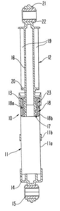
With particular reference to Figures 1 and 2, the shock
absorber 10 substantially consists of a cylindrical sleeve 11 and
a piston 12. The sleeve 11 preferably comprises a metal sheath
lla and a holding case llb of synthetic material, e.g. plastic,
in which the sheath lla is securely fitted. The piston 12, on
the other hand, is made of a synthetic material and is slidably
m~unted inside the sleeve 11.
21S81~
Altkough the sleeves of conventional shock absorbers are
usually made of a machined metal tube, in the case of the shock
absorber 10 according to the present invention, the cylindrical
member, i.e. sheath lla, of the sleeve is formed from a
sheet-metal blank that is first cut to length and then rolled up
so as to become cylindrical, the edges of the sheet-metal blank
being arranged to coincide with a generatrix of the cylinder.
Such a sheath proves to be much more convenient and
cost-effective to manufacture, since it allows processing under
less stringent tolerance requirements. The rolled up piece of
sheet metal is held in the holding cage llb so that the sheet
metal will retain its cylindrical shape.
The holding cage llb of the sleeve 11 has an end portion 13,
which is open and flared in order to facilitate the insertion of
the piston 12 therethrough, and an opposite end portion 14. A
bush 15 is inserted through the opposite end portion 14 of the
holding cage llb, transversely with respect to the longitudinal
axis of the shock absorber.
The bush 15 is adapted to receive a pin (not shown), which
is fixed to the base of the washing machine and on which the
sleeve 11 is capable of oscillating when the washing tub assembly
of the machine undergoes stresses and unbalance loads generated
during the operation of the washing machine.
The piston 12 basically comprises a hollow cylindrical rod
16, and a head 17 formed of a friction ring 18 fixed to the rod
16 at an end portion of the rod 16 located in the sleeve 11. The
friction ring 18 includes a carrier 18a fixed to the rod, and a
friction-generating member 18b held by the carrier so as to
contact the inner peripheral surface of the sleeve 11. The
friction-generating member 18b can be made of a
polyurethane-based elastomer. The rod 16 is provided with outer
~1~8~04
longitudinal ribs 19 extending a substantial distance over its
total length, and which guide the piston 12 within the sleeve 11.
The ribs 19 terminate, closest to the head 17 of the piston 12,
at an annular shoulder 20. The function of the annular shoulder
20 will be described later on.
At its other end portion that is located externally of the
sleeve 11, the piston 12 terminates at a head 21 in which a bush
22 is inserted transversely with respect to the longitudinal axis
of the shock absorber. The bush 22 is adapted to receive a pin
(not shown) which is attached to the washing tub assembly of the
machine and on which the piston 12 can oscillate during the
operation of the washing machine.
According to the present invention, another friction ring 23
is mounted on the rod 16 of the piston 12, between the head 17 of
the piston 12 and the annular shoulder 20. The friction ring 23
also has a friction-generating member which can be made of a
polyurethane-based elastomer. ~owever, unlike the friction ring
18, the friction ring 23 is capable of sliding freely along the
rod 16 because the carrier of the friction ring 23 is not locked
in a groove as is the carrier 18a.
As is also quite apparent from the figures, the annular
shoulder 20 has an outer diameter that is larger than the inner
diameter of the friction ring 23.
Figure 1 shows the shock absorber 10 in its state of r l~imllm
extension, corresponding to a resting, no-load condition or a
condition in which a minimum oscillatory load is imposed
thereupon by the washing tub assembly of the clothes washing
machine. The head 17 of the piston 12 is located closest to the
end portion 13 of the sleeve 11 and is in contact with the
f~iction ring 23, which in the figure appears to be pulled
upwards by the sliding movement of the head 17.
~1~8~04
When the washing machine starts to operate, oscillatory and
downward compression loads are generated and imposed on the
washin, tub assembly, so that the need arises for the loads and
stresses to be dampened by the shock absorber. Therefore, the
shock absorber will oscillate on the pins that are associated
with the bushes 15 and 22, while the piston is pressed downwards
into the sleeve 11.
According to the present invention, the rod 16 of the piston
12 will initially move into the sleeve 11, thereby generating a
dampening or braking friction between the friction ring 18 of the
head 17 and the inner peripheral wall of the sleeve 11. Then, as
the unbalance load increases, the piston 12 will keep sliding
further into the sleeve 11 until the annular shoulder 20 is
brought into contact with the second friction ring 23, thereby
causing the second friction ring 23 to also begin creating a
dampening or braking friction. In this way, a progressively
variable dampening action responsive to the actual unbalance
loads imposed on the washing tub assembly is achieved.
- Figure 2 shows the shock absorber in a state in which a
considerable load is imposed thereupon. In the extreme, i.e.
under a condition that for all practical purposes will actually
never be reached, the friction ring 23 may descend into contact
with the head 17.
Figures 3 and 4 illustrate a second embodiment of a shock
absorber according to the present invention, wherein features
similar to those of the first embodiment shown in Figures 1 and 2
are designated by the same reference numerals.
This second embodiment of the shock absorber according to
the present invention differs from the first embodiment in that
there are three friction rings 23, 24 and 25 mounted so as to be
freely slidable along the rod 16 of the piston 12. The
2~58~4
intermediate friction rings 24 and 25 are disposed between the
friction ring 18 of the head 17 of the piston 12 and the second
friction ring 23.
Furthermore, annular projections 26, 27 and 28 are
appropriately formed on the outer surface of the rod 16 of the
piston 12. The annular projections 26, 27 and 28 have outer
diameters larger than the inner diameters of the friction rings
24 and 25 to cause them to slide when the shock absorber 10 is
progressively loaded and to keep the friction ring 25 duly spaced
apart from the friction ring 18. And, the respective distances
between the shoulder 20 and the annular projection 26, the
projections 26 and 27, and the projections 27 and 28 are
different in order to cause a progressively variable dampening
effect to take place, owing to the sequential manner in which the
friction rings 18 and 23-25 are actuated. In particular, these
distances progressively decrease from the shoulder 20 to the
annular projection 28, so that the axial distance over which the
friction ring 23 can slide along the piston rod is greater than
that over which the ring 24 can slide, and the distance over
which the ring 24 can slide is greater than the distance over
which the ring 25 can slide.
The shock absorber according to the invention is therefore
technically innovative and advantageous over prior-art shock
absorbers, because it produces dampening effects which are
variable in a progressive manner according to the different
unbalance or oscillatory loads exerted thereon by the washing tub
assembly of the washing machine. In other words, the shock
absorber has a desirable self-adjustment characteristic by which
the magnitude of the dampening force created corresponds to the
magnitude of the load to which the shock absorber is subjected.
~1~81Q~ -
In fact, when starting from the mi~;mt~m extension of the
shock absorber (Figs. 1 and 3), corresponding to minimum load
conditions of the washing tub assembly, the dampening effect is
produced when the load exerted on the shock absorber by the
washirg tub assembly increases to compress the shock absorber
(Figs. 2 and 4). Such a compression initially causes the piston
12 to begin retracting into the sleeve 11 so that friction is
generated by the first ring 18 inside the sleeve 11. Thereafter
(with reference to the Figs. 3 and 4, for example) the
displacement of the piston rod 16 brings the annular projection
27 against the respective friction ring 25 and, by causing the
latter to slide, brings about an increase in the dampening effect
due to the additional friction created by the ring 25 at the
inner peripheral wall of the sleeve 11. Then, as the
displacement of the piston rod 16 continues, the annular
projection 26 engages the corresponding friction ring 24.
Finally, the shoulder 20 engages the friction ring 23, thereby
bringing about the largest dampening effect.
Therefore, the number of friction rings that are slid along
the surface of sleeve 11 depends upon the magnitude of the
unbalance or oscillatory load being exerted upon the shock
absorber by the washing tub assembly, whereby the required
dampening effect is produced. It has been found experimentally
that the present invention enables all oscillations of a typical
washing tub assembly to be effectively dampened, including
high-frequency, low-amplitude oscillations that are the most
annoying and troublesome vibrations generated by a clothes
washing machine.
It will be appreciated that the described shock absorber may
be subject to various changes and modifications, in particular as
far as the number of slidable friction rings 23-25 is concerned,
21~81~Q
without departing from the scope of the present invention as
defined by the appended claims.