Note: Descriptions are shown in the official language in which they were submitted.
h
1
A FIRE PROTECTION INSTALLATION
The present invention relates to a fire protection
installation of the type comprising a normally dry
network of sprinklers suitable, whenever the dry network
of sprinklers is put to atmospheric pressure due to said
network of sprinklers being opened, for being fed with
water via a control station that is connected to a supply
of water under pressure.
The purpose of a sprinkler installation is to detect
the seat of a fire, to raise the alarm, and to extinguish
it as it begins, or at least contain it in such a manner
as to ensure that it can be properly extinguished by
means available in the establishment fitted with said
installation or by the fire brigade.
In premises where there is no risk of freezing, the
sprinkler network may be "wet", i.e. it may be
permanently filled with water.
However, when there is a risk of freezing, the
sprinkler network must be "dry", i.e. empty of water,
since the freezing of a wet installation can damage that
installation and thus give rise to a risk of water
damage, and above all, to a risk of the installation
being out of operation for a greater or lesser length of
time as required for bringing it back into operation.
In dry installations, the sprinkler network is
maintained under air that is permanently compressed. A
drop in pressure in the pressurized air sprinkler network
due to a sprinkler opening because it has detected a fire
causes a valve in a control station to open, thereby
triggering the alarm and putting the sprinkler network
into communication with the supply of water under
pressure.
The drawback of present dry installations is that
the air contained in the network is at a pressure of at
least 2 bars. This gives rise to a relatively lengthy
period of time to exhaust air from the network after it
has opened, and in certain installations that can be
. c w t=
2
quite unacceptable, and it also requires the installation
to be provided with a compressor device enabling such
pressures to be obtained. The high pressure also gives
rise to condensation inside the sprinkler network,
thereby leading back to the risk of ice forming therein
due to freezing.
The object of the present invention is to propose an
installation of the above-mentioned type, in which
putting a dry sprinkler network to atmospheric pressure
gives rise to a quicker reaction time.
According to the invention, this object is achieved
by the fact that the network of sprinklers is evacuated,
and is normally maintained at a pressure that is lower
than atmospheric pressure.
Advantageously, the control station comprises a
three-port valve body containing a non-return valve
member, said valve body having a water inlet duct
connected to the water supply and normally closed by the
valve member, a control chamber separated from the inlet
duct by the valve member, an outlet duct connected to the
evacuated network of sprinklers and suitable for being
put into communication with the inlet duct by
displacement of the valve member, and a first branch
connecting the inlet duct to the control chamber and
enabling equal pressures to be maintained in the inlet
duct and the control chamber so that the valve member
closes the inlet duct and isolates the outlet duct, and
an actuator is provided in a second branch
connecting the control chamber to the evacuated network
of sprinklers, said actuator being suitable for keeping
said second branch closed so long as the network of
sprinklers is evacuated, and for permanently opening said
second branch when the pressure in the network of
sprinklers exceeds a predetermined threshold pressure
below atmospheric pressure, thereby causing the pressure
in the control chamber to drop and the valve member to
open.
3
The actuator comprises a cylinder body having an
axial orifice connected to the evacuated sprinkler
network and a radial orifice connected to the control
chamber, a plug slidably mounted in said cylinder body
and suitable for closing both the axial orifice and the
radial orifice when in a closed position and for putting
them into communication with each other when in an open
position, resilient means interposed between the plug and
the cylinder body and designed to urge the plug relative
to cylinder body away from its closed position towards
its open position whenever the pressure in the evacuated
sprinkler network exceeds said predetermined threshold
pressure, and an external handle connected to the plug by
a control rod enabling the plug to be moved into its
closed position while the sprinkler network is being
evacuated, and also making it possible to trigger opening
of the valve member manually.
The cylinder body of the actuator further includes a
second radial orifice connected to a water alarm network
and suitable for being closed by the plug when in its
closed position and for communicating with the control
chamber when the plug is in its open position.
The present invention also relates to a sprinkler
specially adapted for the installation of the invention
and of the type comprising a coupling for coupling to a
duct, an outlet orifice provided in said coupling, a
bracket secured to the coupling, and a fuse disposed
between the orifice and the bracket, and closing said
orifice
According to the invention, means are provided
between the outlet orifice of the sprinkler and the fuse
for positively opening said orifice in the event of the
fuse being destroyed.
Said means include resilient means interposed
between said orifice and said fuse. The resilient means
comprise a compression spring bearing against a collar
provided in the orifice of the sprinkler and against a
r f~' t 63 ,~ r,
tP V !s E
4
tee closing the orifice and having a cradle for
supporting the fuse.
Other advantages and characteristics of the
invention appear on reading the following description
given by way of example and made with reference to the
accompanying drawings, in which:
Figure 1 is a diagram of a fire protection
installation of the present invention;
Figure 2 is a detail view on a larger scale showing
the control actuator of the installation in section;
Figure 3 is an axial view of the Figure 2 actuator;
Figure 4 is a section through a sprinkler of the
invention; and
Figure 5 shows the collar of the sprinkler.
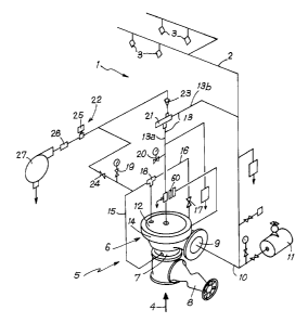
In Figure 1, reference 1 designates a fire
protection installation which includes an evacuated
network 2 of sprinklers 3 suitable for being connected to
a supply 4 of water under pressure via a control
station 5.
The control station 5 comprises, in particular, a
deluge type three-port valve 6 having an inlet duct 7
connected to the water supply 4 via a stop cock 8, an
outlet duct 9 communicating with the sprinkler network 2
via a duct 10 connected to a vacuum pump 11, and an upper
control chamber 12 connected to the duct 10 by a second
branch 13 in which an actuator 21 is provided to control
opening of a non-return valve member in the form of a
clapper 14 disposed inside the valve 6 and normally
closing the inlet duct 7 and the outlet duct 9.
When the valve member 14 is in its normal, closed
position, the inlet duct 7 is not in communication with
the outlet duct 9.
A first branch 15 connects the inlet duct 7 to the
control chamber 12 so that, when the valve member 14 is
in its normal position, i.e. its closed position, the
same pressure is maintained in the control chamber 12 as
in the inlet duct 7. This first branch 15 also
C
4 '~ ~.; n ~ t~
.~ e.i ~ ;,r Yr
communicates with the supply 4 of water under pressure
via a duct 16 that is fitted with a valve 17 for priming
the valve 6. A calibrated orifice 18 is provided where
the duct 16 connects to the first branch 15. A pressure
5 gauge enables the pressure in the first branch 15 to be
measured, and a second pressure gauge 20 enables the
water pressure in the second branch 13 to be measured
between the actuator 21 and the control chamber 12.
The second branch 13 is connected to a water alarm
circuit 22 via the actuator 21 and a non-return valve 23.
The water alarm circuit 22 may also be put into
communication with the first branch 15 via a valve 24 for
the purpose of testing that the alarm circuit 22 is
operating properly.
When the installation 1 is in its normal condition,
the actuator 21 closes the second branch 13 and the valve
member 14 closes the outlet duct 9. In this way, the
sprinkler network 2 and the duct 10 are disconnected from
the supply 4 of water under pressure and can be evacuated
by the vacuum pump 11. The water alarm circuit 22 is
also dry.
Reference 25 designates an alarm pressure switch,
reference 26 a strainer, and reference 27 a water alarm
motor.
Figures 2 and 3 show the actuator 21 in detail.
The actuator comprises a cylinder body 30 having an
axial orifice 31 provided in a coupling 31a with a duct
13b leading to the duct 10, and two diametrically
opposite radial orifices 32 and 33 provided in couplings
34 and 35 respectively coupled with a duct 13a leading to
the control chamber 12 and with the water alarm circuit
22. The end of the cylinder body 30 opposite from its
axial orifice 31 is closed by a knurled cap 36. A plug
37 is slidably mounted in the internal cavity 38 of the
cylinder body 30. The plug 37 is secured to a rod 39
that passes through the cap 36 and that carries a handle
at its outside end. A traction spring 41 has one of
CA 02158200 2005-04-05
6
its ends held by the cap 36 and its other end held by the
plug 37. A cylindrical sealing membrane 42 is interposed.
betweew the plug 37 and the cap 36. The ducts 13a and
13b constitute the above-described second branch 13. The
internal cavity 38 between the plug 37 and the cap 36 is
normally at atmospheric pressure. ,
The plug 37 can take up two positions: a closed
position as shown in Figure 2,, where the plug closes all
three orifices 31, 32, 33; and an open or triggered
position in which the plug 37 is held towards the cover ,
36 by the traction spring 41, with the orifices 31, 32,
33 then communicating with one another.
Figures 4 and 5 show a sprinkler 3 for use in the
installation i of the invention. The sprinkler 3
includes a coupling 50 for fixing to the pipework of the
network 2, which coupling has a central orifice 51 that
is normally closed by a fuse 52, e.g. a bulb, bearing
against a bracket 53 that is secured to the coupling 50,
and a deflector 54 that is fixed,on the bracket 53 facing
the orifice 51. A collar 55 is mounted in the orifice 51
and serves as an abutment for a first end of a
compression spring 56 whose other end bears against the
bottom face of a tee 57 that normally closes the orifice
51 and that has, on its outside face, a cradle 58 for
supporting the base of the bulb. When clamped on the
fuse 52, the tee 57 and the spring 56 are under
compression.
When the temperature of ambient air rises above a
temperature that is determined as a function of the type
of fuse 52, the fuse bursts and the spring 56 relaxes,
thereby ejecting the tee 57, and thus connecting the
sprinkler network 2 to atmospheric pressure.
The traction spring 41 in the actuator 21 is
calibrated so that when the sprinkler network 2 is at a
pressure that is lower than atmospheric, then the suction
in the duct I3b is capable of holding the plug 37 in its
closed position, and so that when the pressure in the
..,
7
duct 13b increases to approach atmospheric pressure, due
to a sprinkler fuse 52 breaking, the plug 37 is moved
towards its open position under force from the traction
spring 41 and from the pressure difference between the
orifice 31 and the cavity 38.
When the actuator 21 is in its position for opening
the second branch 13, the pressure in the control chamber
12 drops suddenly and the valve member 14 opens,
supplying water to the sprinkler network 2 via the outlet
duct 9 and the duct 10. The duct 13b also fills with
water, as does the alarm circuit 22. Thereafter, the
actuator 21 remains automatically in its open position.
The procedure for readying the installation 1 for
operation is as follows: The stop cock 8 is closed, the
vacuum pump 11 is put into operation, and the plug 37 is
pressed against the orifice 31 by pushing against the
handle 40. Once the suction in the sprinkler network 2
is sufficient to hold the actuator 41 in its closed
position, the handle 40 is released and the valve 17 is
opened to put the control chamber 12 under pressure.
Equilibrium within the valve 6 and closure of the clapper
14 are obtained via the safety valve 60 and the
calibrated orifice 18. Once identical pressures are
indicated in the inlet duct 7 and in the control chamber
12, by readings of the pressure gauges 19 and 20, the
valve 6 is ready for operation. It then remains merely
to open the stop cock 8. The pressure in the sprinkler
network 2 is about 0.6 bars below atmospheric pressure.