Note: Descriptions are shown in the official language in which they were submitted.
CA 02158320 2004-06-17
1
A TRACK MAINTENANCE MACHINE
The invention relates to a track maintenance machine
comprising a machine frame and a superstructure located
thereon and containing an engine.
Track maintenance machines of this kind are known in many
different constructions and also for different operational
uses. Generally the various construction sites for the
operational use of a track maintenance machine are situated in
the fairly immediate vicinity so that the machine can be
transferred relatively easily under its own propulsion or in a
train formation. However, for construction sites located
abroad, possibly even on another continent, very complicated
conversion operations as well as special transport equipment
are required so that the track maintenance machine can be
shipped there, for example.
The object of the present invention is now to provide a
track maintenance machine of the type previously defined
which, with minimum conversion effort, can be quickly and
easily transported even to construction sites which are
particularly far away.
This object is achieved according to the invention with a
track maintenance machine of the type previously defined in
that a horizontally extending bottom b~us~uary surface of the
machine frame has attachment devices for detachably securing
on-track undercarriages as well as a coupling for connecting
an energy supply line to other energy supply lines connected
to a motive drive and to a braking device of an on-track
undercarriage.
CA 02158320 2004-06-17
2
Because of the design of the machine frame, which is
limited vertically downwards to the level of the on-track
undercarriages, it can be easily transported together with the
superstructure like a container, the machine frame forming the
base surface, as it were, for problem-free supporting of the
machine unit without its undercarriages. The conversion
operations required for this are essentially reduced to
detaching the on-track undercarriages from the machine frame,
which is quick and simple to perform. In the event that this
kind of transfer to a very distant construction site is
performed on frequent occasions, two sets of on-track
undercarriages can expediently also be provided for each
construction site, so that the on-track undercarriages
themselves do not have to be transferred. However, the solution
according to the invention also offers the advantage of
mounting the machine unit without its undercarriages on a
track-or road-going transport vehicle. Even its use on tracks
of different gauges does not present any problems when two sets
of on-track undercarriages are used.
The object of the present invention is to provide a track
maintenance machine comprising a machine frame and a
superstructure located thereon and containing an engine,
characterized in that a horizontally extending bottom boundary
surface of the machine frame has attachment devices for
detachably securing on-track undercarriages as well as a
coupling for connecting an energy supply line to other energy
supply lines connected to a motive drive and to a braking
device of the on-track undercarriage.
Another object of the present invention is to provide a
machine, characterized in that the machine frame is defined by
CA 02158320 2004-06-17
2a
the bottom boundary surface and by a top boundary surface
running parallel thereto.
A further object of the present invention is to provide a
machine, characterized in that attachment devices for
detachably securing vertically adjustable lifting jacks as well
as a hydraulic coupling for the detachable connection of
hydraulic lines connected to the lifting jacks are arranged on
the machine frame in the region of ends which extend
perpendicularly to the longitudinal direction of the frame.
A still further object of the present invention is to
provide a machine, characterized in that attachment devices for
detachably securing a turning device comprising a vertically
adjustable supporting jack which is rotatable about a vertical
axis, as well as a coupling for connecting an energy supply
line for the vertical adjustment of the turning device are
provided on the bottom boundary surface in the region of the
centre of gravity of the machine.
The object of the present invention is to provide a
machine, characterized in that the superstructure has four side
walls and a roof plane extending parallel to the boundary
surfaces of the machine frame to form a cabin enclosing the
superstructure, and in that between the cabin and one end of
the machine frame, a vertically and laterally adjustable crane
jib connected to a working unit is connected to the top
boundary surface.
Another object of the present invention is to provide a
machine, characterized in that the working unit is a flash-butt
welding unit.
CA 02158320 2004-06-17
2b
A further object of the present invention is to provide a
machine, characterized in that the cabin and, other working
units located outside the cabin are arranged within the
outlines formed by the ends of the platform-shaped machine
frame.
A still further object of the present invention is to
provide a machine, characterized in that the machine frame is
formed from two frame parts, arranged one following the other
in a common plane and situated at a distance from one another
in the longitudinal direction of the machine, which are joined
together by a connecting part of an upwardly recessed design.
The object of the present invention is to provide a
machine, characterized in that the connecting part is connected
to the vertically adjustable working unit, the height of the
working unit being designed to be smaller than the recess
height of the connecting part.
The invention is described in more detail in the following
with the aid of exemplary embodiments shown in the drawings, in
which:
Fig. 1 shows a side view of a track maintenance machine
according to the invention;
Fig. 2 shows a view of the track maintenance machine in
the longitudinal direction of the machine, with extended
lifting jacks;
Fig. 3 shows a view of the track maintenance machine in a
condition suitable for container-shipment;
_ 2I.3~~20
3
Fig. 4 shows another embodiment of a track maintenance
machine with a different frame construction, and
Fig. 5 shows a simplified, three-dimensional
representation of a machine frame.
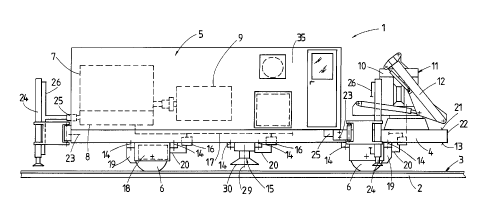
A track maintenance machine 1 shown in Fig. 1 and 2 for
welding rails 2 of a track 3 is essentially composed of a
machine frame 4, a superstructure 5 and on-track
undercarriages 6. The superstructure 5 contains an engine 7,
a hydraulic pump 8 and a generator 9 as well as a working unit
11 which is designed as a flash-butt welding unit 10 and which
is connected to a crane jib 12 adapted for rotation and
vertical adjustment by means of drives.
A bottom boundary surface 13 extending horizontally or
parallel to the plane formed by the wheel contact points of
the on-track undercarriages 6 has attachment devices 14
designed as screw connections for detachably securing the on-
track undercarriages 6 and a .vertically adjustable turning
device 15 provided in the region of the centre of gravity of
the machine 1. In addition, couplings 16 are also provided
for connecting an energy supply line 17 connected to the
hydraulic pump 8 to other energy supply lines 20 connected to
a motive drive 18 and a braking device 19 of an on-track
undercarriage 6 as well as to the turning device 15.
The machine frame 4 which extends in one plane is defined
by the bottom boundary surface 13 and by a top boundary
surface 21 running parallel thereto and simultaneously forming
the base surface for the superstructure 5. Other attachment
devices 23 for detachably securing vertically adjustable
lifting jacks 24 are provided in the region of ends 22 of the
machine frame 4 extending perpendicularly to the longitudinal
direction of the frame. In addition, hydraulic couplings 25
are provided in the region of the lifting jacks 24 for the
detachable connection of hydraulic lines 26 connected to the
- ~.~ ~~32~
4
lifting jacks 24.
The superstructure 5 has four side walls 27 and a roof
plane 28 extending parallel to the boundary surfaces 13,21 of
the machine frame 4 to form a cabin 35 enclosing the engine 7
and the generator 9.
As is particularly clear from Fig. 1 and 2, the
superstructure 5 is located within the outlines formed by the
edge of the machine frame 4, when the machine 1 is viewed from
above (in the direction extending perpendicularly to the
boundary surfaces 13,21). The crane jib 12, together with the
working unit 11, is also within the aforementioned outlines in
its transfer position.
In working use, the track maintenance machine 1 is
designed to travel on the track 3 from one welding site to the
next with the aid of the motive drive 18, in order to perform
the desired welding operations using the flash-butt welding
unit 10 which is lowered over the end 22 onto the track 3. If
required, the entire machine 1 can be rotated around 180° with
the aid of a vertically adjustable supporting jack 30 of the
turning device 15 which is rotatable about a vertical axis 29,
in order to change the working direction. Also, lowering the
lifting jacks 24 enables the track maintenance machine 1 to be
lifted off the track 3 for the purpose of self-loading.
To enable the track maintenance machine 1 also to be
transported as a container to very distant construction sites
in as simple a manner as possible, the attachment devices 14
and the couplings 16 are released, enabling the two on-track
undercarriages 6 and the turning device 15 to be removed from
the machine frame 4. This is expediently performed with self-
lifting of the track maintenance machine 1 through the use of
the lifting jacks 24. A transport wagon is then moved under
the lifted track maintenance machine 1, which can be lowered
onto the transport wagon by retraction of the lifting jacks
_ ~~ ~~32~
24. By releasing the attachment devices 23 and the hydraulic
couplings 25, the lifting jacks 24 can then be removed. In
this condition, shown in Fig. 3, the track maintenance machine
1 can be loaded on a ship as a container, for example, and can
be transported to a very distant construction site. It is
also possible, however, to use the track maintenance machine 1
for welding rails without the attachment of on-track
undercarriages 6, for instance by placing it on a track-going
transport wagon. Similarly, it is possible, if appropriate,
for road-going undercarriages instead of on-track
undercarriages 6 to be attached to the bottom boundary surface
13 of the machine frame 4.
As is shown in Fig. 4, the machine frame 4 may also be
composed of two frame parts 31 located in one plane, arranged
one following the other and at a distance apart in the
longitudinal direction of the machine. There is therefore a
bottom boundary surface 13 located in one plane, so that the
track maintenance machine I can similarly be loaded as a
container after the on-track undercarriages 6 have been
removed. The two frame parts 31 are joined together by a
connecting part 32 of an upwardly recessed design. A working
unit 11 designed as a rail welding unit, for example, is
secured to the said connecting part so as to be vertically
adjustable. The height (h) of the working unit 11 is designed
to be smaller than the recess height (H) of the connecting
part 32.
Figure 5 shows another example of a machine frame 4 which
is composed of two longitudinal spars 33 extending parallel to
one another in the longitudinal direction of the frame and
transverse spars 34 joining these together. The bottom
boundary surface 13 is this case formed by the respective
undersides of the longitudinal spars 33.