Note: Descriptions are shown in the official language in which they were submitted.
2158803
REMOVABLE ORIFICE PLATE FOR
INK JET PRINTHEAD AND SECURING APPARATUS
The present invention generally relates to
printhead assembly apparatus used in ink jet printers,
and more particularly relates to a removable orifice
plate and associated securing apparatus for such
printhead assemblies.
A conventionally fabricated printhead assembly for
an ink jet printer typically includes a piezoelectric
ceramic body portion through which a spaced apart
series of parallel ink receiving chambers or cavities
extend from the front end of the body to its rear end.
- 2158803
The open chamber ends at the rear end of the body are
suitably communicated with the interior of an ink
reservoir to receive ink therefrom, and an orifice
plate, which is comprised of a dissimilar material such
as a polymer, is secured over the open front end of the
body using a generally planar layer of high strength
adhesive material. A spaced series of ink discharge
orifice openings are formed through the orifice plate,
and are aligned with and positioned over the open front
ends of the body chambers.
In such conventional printheads, the orifice
plates are permanently secured to the front end of the
printhead assembly by a strong adhesive. Generally,
the orifice plate is secured in place by an adhesive
that is applied either to the rear end surface of the
orifice plate or the front end surface of the printhead
body. The typical adhesives that are used to secure
the orifice plate to the printhead body are "activated"
or cured by subjecting the printhead assembly to high
temperatures. After the adhesive has cured, the
orifice plate is permanently bonded to the printhead
body.
Because the orifice plate is permanently bonded to
the printhead assembly, several disadvantages can arise
with the use of these conventional ink jet printhead
21~8803
assemblies. For example, because of the differing
coefficients of thermal expansion between the
materials, the ink discharge orifices of the orifice
plate can become misaligned with the ink receiving
chambers when the printhead assembly is subjected to
the high temperatures necessary to cure the adhesive
properly. Since the ink discharge orifices and its
features are extremely small, the dimensional
tolerances on the size and location of these features
are equally small. Therefore, any misalignment that
may occur during the curing process can have a
detrimental effect on the quality and the performance
of the ink jet printhead. Thus, if a misalignment
occurs during the assembly process that substantially
affects the print quality, the entire printhead
assembly must be disposed of because there is no
effective way to easily remove the orifice plate from
the printhead. If the defective printhead is
inadvertently sold and used by a purchaser, the
purchaser must either return the printhead to the place
of purchase or throw the entire defective printhead
assembly away since the orifice plate is permanently
attached to the printhead body. Additionally, the
conventional adhesives that may be used to attach the
orifice plate to the body portion, must also act as a
2158803
sealing gasket to seal the printhead assembly and
prevent ink from leaking between the channels or
various segregated areas of the printhead.
Unfortunately, however, the strong solvent nature of
most inks chemically attacks many common adhesives,
thereby weakening the adhesive and causing structural
failure and leakage. Again, if structural failure or
leakage occurs as the result of the adhesive failure,
the entire printhead assembly must be thrown away
because the purchaser has no way of effectively
reattaching and sealing the orifice plate to the
printhead body.
In other instances, after the adhesive is applied
to the body portion and during the step in which the
orifice plate is positioned on the printhead body, the
adhesive may seep into and plug the ink receiving
chambers and the orifice holes. If these plugged
printheads are inadvertently used by a purchaser, the
purchaser, aqain, has no alternative but to either
return the printhead, throw the entire printhead
assembly away or endure an unacceptable print quality.
Additionally, during operation of the printhead, the
ink can become dry and plug several of the tiny
discharge orifices in the orifice plate. When this
- 2158803
occurs, the purchaser must either endure a poor print
quality or throw the entire printhead assembly away.
In each instance just described, the way in which
the problem of a defective orifice plate is remedied by
the purchaser, and in many instances by the
manufacturer, is to dispose of the entire printhead
assembly. These end results are undesirable because
they are costly and wasteful to both the manufacturer
and the purchaser.
Therefore, it can readily be seen that there is a
need in the art for a securing assembly that will allow
the orifice plate to be easily removed and replaced in
the case of defect or failure. The present invention
provides an apparatus that addresses these needs.
In carrying out principles of the present
invention, in accordance with a preferred embodiment
thereof, there is provided a removable orifice plate
securing structure for use in conjunction with an ink
jet printer printhead assembly. The conventional
printhead assembly has a printhead body portion, a
front end surface, a rear end surface and ink receiving
chambers opening outwardly through the front end
surface of the printhead body portion. Also included
with the conventional printhead assembly is a removable
-
2158803
orifice plate that has ink discharge orifices formed
therethrough, a front end surface and a rear end
surface.
The orifice plate securing structure comprises an
orifice plate mounting member having a rear end portion
disposed in an opposing relationship with the front end
surface of the printhead body portion, a front side
surface and an opening extending outwardly from the
rear end portion to the front side surface. The
orifice plate mounting member is configured to
removably secure the orifice plate between the front
side surface of the orifice plate mounting member and
the front end surface of the printhead body portion in
an operative alignment position with the ink receiving
chambers. The opening is configured to allow ink from
the ink discharge orifices to operatively pass
outwardly from the printhead assembly through the
orifice plate mounting member.
The orifice plate securing structure also
comprises a securing means for removably securing the
orifice plate mounting member and the orifice plate to
the printhead body portion in an operative alignment
position with the ink receiving chambers. In one
embodiment, the securing means is integrally formed
with the orifice plate mounting member and further has
- 2158803
a clamping end portion that is removably securable to
the rear end surface of the printhead body portion. In
yet another embodiment, the securing means is a spring
formed clamping mechanism having first and second end
portions wherein the first end is removably securable
to the front end surface of the orifice plate mounting
member and the second end is removably securable to the
rear end surface of the printhead body portion. In a
preferred embodiment of this aspect of the invention,
the securing means are a pair of spring formed clamping
mechanisms that are securable to the opposite sides of
the orifice plate mounting member and the printhead
body portion.
A sealing means is also provided in the embodiment
described above. The sealing means is configured to
effectively seal and prevent leakage of ink between the
ink receiving channels and from the printhead assembly
in general. The sealing means may be an independent
sealing material, or it may be a part of the orifice
plate itself. Preferably, however, the sealing means
is a thin layer of silicon that is secured to the rear
side surface of the orifice plate. The sealing means
is also configured with openings to allow the ink to
flow from the ink receiving channels through the ink
discharge orifices in the orifice plate. The openings
- 2158803
may be formed simultaneously with the formation of the
ink discharge orifices by laser ablation when the
sealing means is a part of the orifice plate, or the
openings may be formed independently when the sealing
means is separate from the orifice plate.
In yet another embodiment, the orifice plate
mounting member is a housing member having an open rear
end portion, a front side surface, and an inner side
surface and an outer side surface extending rearwardly
from the front side surface to the open rear end
portion. In this particular embodiment, the front side
surface has an opening therein configured to allow ink
from the ink discharge orifices to operatively pass
outwardly through the opening, and the inner side
surface has a recessed portion therein that is adjacent
the opening and configured to receive the orifice
plate. The orifice plate may be secured to the
recessed portion by an adhesive if so desired,
otherwise, the orifice plate is easily removable from
the recessed portion. Additionally, the open rear end
portion of the housing member is configured to slidably
receive the front end surface of the printhead body
portion.
In another aspect of the present invention, there
is provided a printhead assembly for use in an ink jet
2158803
printer. The assembly comprises a printhead body, a
removable orifice plate, an orifice plate mounting
member and a securing means for removably securing the
orifice plate and orifice plate mounting member to the
printhead body portion. The printhead body portion is
formed from a piezoelectric material and has a front
end surface, a rear end surface and a spaced apart
interior series of ink receiving chambers opening
outwardly through the front end surface. The removable
orifice plate has an ink discharge orifice array formed
therethrough, a rear side surface disposed in an
opposing, closely adjacent relationship with the front
end surface of the printhead body portion and a front
side surface.
The orifice plate mounting member, securing means
and sealing means as previously described are also
provided in this particular embodiment, including the
previously discussed alternate embodiments of each. In
yet another aspect of this particular embodiment, the
mounting member may also be a housing member as
previously described above for the other embodiments.
The foregoing has outlined rather broadly the
features and technical advantages of the present
invention so that the detailed description of the
invention that follows may be better understood.
2158803
--10--
Additional features and advantages of the invention
will be described hereinafter which form the subject of
the claims of the invention. Those skilled in the art
should appreciate that they can readily use the
disclosed conception and specific embodiment as a basis
for designing or modifying other structures for
carrying out the same purposes of the present
invention. Those skilled in the art should also
realize that such equivalent constructions do not
depart from the spirit and scope of the invention as
set forth in the appended claims.
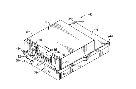
FIG. lA illustrates a perspective view of a
printhead assembly with the orifice plate mounting
member and orifice plate secured thereto by the
securing means;
FIG. lB illustrates a cross-sectional side view of
FIG. lA view taken along the line lB-lB;
FIG. 2 illustrates a perspective view of a
printhead assembly with the housing member and orifice
plate secured thereto by the securing means;
FIG. 3 illustrates a perspective exploded view of
FIG. 2;
FIG. 4 illustrates a cross-sectional side view of
FIG. 2 taken along the line 4-4;
2158803
--11--
FIG. 5 illustrates a cross-sectional top view of
FIG. 4 taken along the line 5-5; and
FIG. 6 illustrates a perspective view of the
housing member with the securing means integrally
formed therewith.
Referring initially to FIGs. lA and lB, in a
preferred embodiment thereof, there is provided a
printhead assembly 10 having a printhead body portion
12 with a rear end surface 14 and ink receiving
chambers 16 opening outwardly through a front end
surface 18 of the printhead body portion 12. The
printhead body portion 12 is preferably comprised of a
piezoelectric material, and more preferably, is
comprised of a piezoelectric ceramic material. Closely
adjacent to the front end surface 18 is a removable
orifice plate 20, which may be comprised of a very thin
metallic material or a thermoplastic polymer material,
such as a polyimide, polyester or polysulfone. The
orifice plate 20 is easily removable from the printhead
body portion 12 and is not permanently secured with
adhesive as in conventional printhead assemblies r but
is instead, removably secured by means as described
herein below. The orifice plate 20 has ink discharge
orifices 22 formed therethrough, a front side surface
2158803
- 12 -
24 and a rear side surface 26 disposed in an opposing,
closely adjacent relationship with the front end
surface 14 of the printhead body portion 12.
Positioned and sealing secured between the front
5 end surface 18 of the printhead body portion 12 and the
rear side surface 26 of the orifice plate 20 iS a
sealing means 28 that seals the ink receiving chambers
16 and prevents a flow of ink therebetween and from the
printhead assembly 10 in general. The sealing means 28
may be an independent sealing material, or it may be a
part of or secured to the orifice plate 20. The
sealing means 28 iS also configured with sealing means
openings 30 to allow the ink to flow from the ink
receiving chambers 16 through the ink discharge
15 orifices 22. The sealing means openings 30 may be
formed simultaneously with the formation of the ink
discharge orifices 22 by laser ablation when it is a
part of the orifice plate 20, or they may be formed
independently when the sealing means 28 iS separate
20 from the orifice plate 20. Preferably, the
configuration is in the form of tiny orifices that are
aligned and formed simultaneously by laser ablation
with the formation of the ink discharge orifices 22
when the sealing means 28 iS a part of or secured to
25 the rear side surface 26 of the orifice plate 20.
- 21~8803
-13-
The sealing means 28 is preferably comprised of a
thin layer of silicone that is secured to the rear side
surface 26 of the orifice plate 20. However, the
sealing means 28 may be other types of pre-formed
sealing materials, such as gaskets that may or may not
be attached to the orifice plate 20.
The orifice plate 20 is removably secured to the
front end surface 18 of the printhead body portion 12
by a removable orifice plate moùnting member 32 in
cooperation with a securing means 34. The orifice
plate mounting member 32 has a rear end portion 36
disposed in an opposing relationship with the front end
surface 18 of the printhead body portion 12 and a front
side surface 38. Extending outwardly from the rear end
portion 36 to the front side surface 38 of the orifice
plate mounting member 32 is an mounting member ink
discharge opening 40.
The orifice plate mounting member 32 is configured
to removably secure the orifice plate 20 between the
front side surface 38 of the orifice plate mounting
member 32 and the front end surface 18 of the printhead
body portion 12 in an operative alignment position with
the ink receiving chambers 16. What is meant by
operative alignment is that the ink discharge orifices
22 are properly aligned with the ink receiving chambers
2158803
16 to effectively and accurately discharge the ink from
the printhead assembly lO when the orifice plate 20 and
the orifice plate mounting member 32 are properly
secured to the printhead body portion 12.
The orifice plate mounting member ink discharge
opening 40 is configured to allow ink from the ink
discharge orifices 22 to operatively pass outwardly
from the printhead assembly 10 through the orifice
plate mounting member 32. In other words, none of the
ink discharge orifices 22 are blocked by the orifice
plate mounting member 32, and the orifice plate
mounting member ink discharge opening 40 does not
interfere with the ink jet spray pattern and thus,
effectively allows the ink to be discharged from the
printhead assembly 10.
As previously mentioned, the orifice plate 20 and
the orifice plate mounting member 32 are removably
secured to the printhead body portion 12 by the
securing means 34. While the securing means 34 can be
any type of securing mechanism such as an interlocking
teeth-latchet means or ball and socket means or some
other similar securing means, the securing means 34 is
preferably a spring-formed clamping mechanism, as
illustrated in FIG. lA, that frictionally engages the
printhead body portion 12 and the orifice plate
2158803
-15-
mounting member 32. The securing means 34 preferably
has a first clamping end 42 that is removably securable
to the front side surface 38 of the orifice plate
mounting member 32 and a second clamping end 44 that is
removably securable to the rear end surface 14 of the
printhead body portion 12. In such instances where the
securing means 34 is a spring-formed clamp, the orifice
plate mounting member 32 and the orifice plate 20 are
secured to the printhead body portion 12 by the
clamping force exerted by the securing means 34 at the
opposing ends of the printhead assembly 10.
Preferably, however, the securing means 34 are a pair
of spring formed clamping mechanisms that are securable
to opposite sides of the printhead assembly 10 as
illustrated in FIGs. lA and lB. The securing means 34
may be made of flexible metal or plastic materials.
Alternatively, as will be later described herein,
the securing means 34 may also be integrally formed
with the orifice plate mounting member 32. In such
instances, the securing means 34 may have only one pair
of clamping end portions that are removably securable
to the rear end surface 14 of the printhead body
portion 12.
Turning now to FIGs. 2 and 3, there is illustrated
an alternate embodiment of the present invention. In
-- 2l588o3
-16-
this embodiment, the orifice plate mounting member 32
is a housing member 46 having an open rear end portion
48, a front side surface 50 and an inner side surface
52 and outer side surface 54 extending rearwardly from
the front side surface 50 to the open rear end portion
48. The front side surface 50 has a housing member ink
discharge opening 56 therein configured to allow ink
from the ink discharge orifices 22 to operatively pass
outwardly from the printhead assembly 10 through the
housing member 46. The front side surface 50 of the
housing member 46 is configured to receive the first
clamping end 42 of the securing means 34 and secure the
orifice plate 20 between the housing member ink
discharge opening 56 and the front end surface 18 of
the printhead body portion 12. The sealing means 28 is
positioned between the rear side surface 26 of the
orifice plate 20 and the front end surface 18 of the
printhead body portion 12 to seal the ink receiving
chambers 16 and the printhead assembly 10 in general.
When the housing member 46 is secured by the securing
means 34, the ink discharge orifices 22 and the sealing
means 28 are secured in operative alignment with the
ink receiving chambers 16.
Turning now to FIGs. 4 and 5, the embodiment just
described is illustrated in cross-section. The inner
2158803
side surface 52 of the housing member 46 has a recessed
portion 58 therein adjacent the housing member ink
discharge opening 56. The recessed portion 58 is
configured to receive the orifice plate 20 within the
interior portion of the housing member 46 and hold the
orifice plate 20 between the housing member ink
discharge opening 56 and the front end surface 18 of
the printhead body portion 12. An adhesive 60 may be
used to hold the orifice plate 20 in the recessed
portion 58, if so desired. Alternatively, however, the
recessed portion 58 may be configured to tightly secure
and hold the orifice plate 20 without the use of an
adhesive.
The housing member 46 and its open rear end
portion 48 are preferably configured to slidably
receive the front end surface 18 of the printhead body
portion 12 and seal it against the rear side surface 26
of the orifice plate 20, as illustrated in FIGs. 4 and
5. When so positioned, the sealing means 28 (see FIG.
3) seals the ink receiving chambers 16 as previously
discussed. Of course, it should be recognized that
alternate embodiments could include those
configurations where the printhead body portion
slidably receives the orifice plate mounting housing
21S8`803
-18-
member to operatively align and seal the orifice plate
with the ink receiving chambers as well.
Turning now to FIG. 6, there is illustrated yet
another embodiment of the housing member 46 having the
securing means 34 integrally formed therewith. The
securing means 34 are preferably formed within the
outer side surface 54 of the housing member 46 with the
second clamping end portions 44 extending rearwardly
therefrom to engage the rear end portions of the
printhead body (not shown).
In operation, if the orifice plate becomes
plugged, the operator may change out the orifice plate
by removing the orifice plate mounting member by
disengaging the securing means from the printhead body
or the mounting member. Once the securing means is
disengaged, the mounting member may be easily removed
from the printhead assembly. The orifice plate may
then be easily accessed and replaced with a new orifice
plate.
In those embodiments where the orifice plate is
adhesively secured to the recessed portion of the
housing member, the entire housing member and orifice
plate will be replaced by a new housing member having
a new orifice plate adhesively secured therein. The
21~8803
--19--
clamps are re-engaged and the printhead is ready to
use.
From the foregoing, it is seen that the present
invention provides a removable orifice plate securing
structure that allows the operator to easily replace
the orifice plate when it has become clogged or
plugged.
Although the present invention and its advantages
have been described in detail, it should be understood
that various changes, substitutions and alterations can
be made herein without departing from the spirit and
scope of the invention as defined by the appended
claims.