Note: Descriptions are shown in the official language in which they were submitted.
215~77
UO 94/21489 PCT/DE94/00304
TRANSLATION
Electric Switch,
Notably Automotive Steering Column Switch
Specification
The invention relates to an electric switch, notably an automotive steer-
ing column switch, featuring a switching lever fitted in the switch casing
and serving to switch at least one electric circuit while having on its
exposed end a spring-loaded push button for actuation of another electric
circuit.
It is generally known to actuate the switching lever of steering column
switches in two planes of movement in order to be able to switch a plural-
ity of functions in a clear manner. Additionally it is frequently custom-
ary to provide the switching lever on its exposed end with a push buttonadapted for actuation in axial direction, to perform additional switching
functions.
Known from DE-OS 30 45 159 is an automotive steering column switch featur-
ing a switching element that pivots about a casing-fixed axis and con-
tains, for one, a catch of flexible arrangement which interacts with a
stationary cam and, for another, a contact bridge for the turn signal
circuit. Uithin the switching element, an actuator lever is pivotably
21S90~7
WO 94/21489 - 2 - PCT/DE94/00304
mounted about a stud which is aligned perpendicularly to the casing-fixed
axis and parallel to the pivotal plane of the switching element. The
actuating lever possesses a spring-loaded catch that interacts with a cam
in the switching element. On the end of the actuating lever rests the
actuating arm of a rocker which by way of its crank is in working connec-
tion, via a slide, with a switching rocker for actuation of the passing
light and for turn signal switching. The actuating lever performs thus two
movements.
Known from DE-OS 29 52 298, furthermore, is a steering column switch which
features a switching arrangement with which the left, or right turn signal
lights can be activated for signaling the direction of travel, and a
switching arrangement capable of influencing the circuit of the head-
lights. The former switching arrangement is actuated by horizontal pivot-
ing, the second by vertical pivoting of an actuating lever. To be able to
perform this movement, the actuating lever is mounted in a switching
element so as to rotate about a horizontal axis, which switching element
is rotatable about a vertical axis by way of two studs that extend into
two casing holes.
Known from DE-PS 33 43 661, moreover, is a steering column switch that
features two electrically interconnected printed circuit boards, of which
one is laminated on both sides and with which printed circuit boards the
movements of the actuating lever of the switch in horizontal and vertical
direction, or plane, enables to switch a plurality of functions, such as
21~9077
W0 94/21489 - 3 - PCT/DE94/00304
parking lights, headlights, low beam, passing lights, turn signal right
and left.
The ob~ective underlying the invention is to provide a switch of the
initially mentioned type which with a horizontal and/or vertical direction
of switching of the switching lever and with a push button arranged on the
end of the switching lever is compact in construction volume.
This ob~ective is inventionally achieved in that the push button is in
working connection, via a spring-loaded connecting rod, with a cross lever
that is located in the axis of rotation of the switching lever and mounted
pivotably while connected on its pivotable end to a spring-loaded switch-
ing member which acts upon contacts.
Achieved by these measures, for one, is a compact design of the switch
and, for another, a reliable transmission of force from the push button to
the switching member. Owing to the arrangement of the pivotable cross
lever in the axis of rotation of the switching lever, the switching func-
tion of the push button can be initiated in any position of the switching
lever, and the cross lever requires virtually no extra installation space.
According to a favorable embodiment of the invention, the push button
features an inner sleeve that is arranged movably and rotationally fixed
on the stem of the switching lever and forms with its outer sheathing the
` 215~Q77
WO 94/21489 - 4 - PCT/DE94/00304
switching lever handle. Obtained thereby is a suitable integration of the
push button in the switching lever.
For a simple realization of the spring-loading of the push button, the
latter features according to a favorable development of the invention in
its inner sleeve a centered stud which bears against the pressure of a
compression spring arranged in the stem of the switching lever.
To assure a reliable pivoting of the cross lever, the ends of the cross
lever situated in the vertical axis of rotation of the switching lever are
according to a further embodiment of the inventional solution of a ball-
shaped design and mounted, each, in a matching socket in the upper casing
half and a corresponding socket in the switching member. The exposed end
of the connecting rod is suitably in contact with the center area of the
cross lever.
In order to achieve a simple spring-loading of the connecting rod, the
axially offset connecting rod is according to a further development of the
invention arranged in axial proximity in the switching lever and possesses
a pro~ection which bears on a spring fitted in the switching lever.
To enable a locking and release of the switching function initiated by the
spring-loaded push button, the switching member coordinated with the push
button connects to catching means which fix its switching position. These
means are preferably comprised essentially of a heart cam and a pawl fea-
21S9077
W0 94/21489 - S - PCT/DE94/00304
turing an elastically movable detent joined to said cam. The switching
element is suitably accommodated here in the lower casing half, in a
fashion horizontally movable against the force of a spring. Furthermore,
the switching element connects preferably, by way of a spring-loaded con-
tact roll, to the contact carrier insert.
The idea underlying the invention will be more fully explained hereafter
with the aid of an exemplary embodiment illustrated in the drawing, which
shows in
Fig. 1, a longitudinal section through a steering column switch;
Fig. 2, scaled up, the detail II in Fig. l;
Fig. 3, a section through the illustration according to Fig. 1, along line
III-III, scaled up;
5 Fig. 4, a section through the illustration relative to Fig. 3, along line
IV-IV;
Fig. 5, a section through the illustration according to Fig. 3, along line
V-V;
Fig. 6, scaled up, an illustration of detail VI in Fig. l; and
0 Fig. 7, a section through the illustration according to Fig. 6, along
line VII-VII.
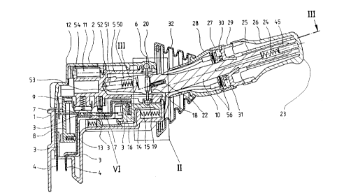
The switch casing of the steering column switch is composed of a lower
casing half 1 and an upper casing half 2 which are joined with the aid of
clips. The lower casing half 1 accommodates a contact carrier insert 3
21~9~7
WO 94/21489 - 6 - PCT/DE94/00304
that is angled repeatedly and whose contact tracks extend into outward
contacts 4. Coordinated with the horizontal top side of the contact
carrier insert 3 is a switching element 5 which pivots horizontally about
an axis of rotation 6, is connected to a switching lever 10 and serves to
S act upon a windshield wiper, while spring-loaded contact bridges 7 fitted
in the switching member S establish a reliable contact. Coordinated with
the downward-angled, vertical part of the contact bridge [sic] insert 3 is
a switching member 8 for single-action switching of the windshield/rear
window wipers, said switching element being vertically movable in guide-
ways provided in the casing. Serving that purpose is an extended ridge 9of the vertically pivotable switching lever 10, which latter is mounted,
spring-loaded, in the switching member 5. The ridge 9 engages a matching
recess in the switching member 8. Arranged in the switching member 8 are
spring-loaded contact rolls 13 for acting upon the appropriate contact
tracks of the contact carrier insert 3. The end of the switching lever 10
situated inside the switching member S accommodates a catch 51 with a roll
52, spring-loaded by a compression spring 50, said roll interacting with
a cam 53 molded to the switching member 5. Additionally, the switching
member S features a spring-loaded catch 11 with a roll 54 interacting with
a cam 12 molded to the upper casing half 2. The mounting points for the
switching member S and the switching lever 10 fitted in the switching
member S intersect, so that the switching lever can be moved both horizon-
tally and vertically.
~15~77
U0 94/21489 - 7 - PCT/DE94/00304
To act upon the circuit of a rear window wiper, a further switching member
14, arranged in the lower casing half 1, is coordinated with the contact
carrier insert; said switching member being movable horizontally against
the force of a spring 15 and establishing by way of a spring-loaded
contact roll 16 in its switching position a dependable electric connection
with the appropriate contact tracks of the contact carrier insert 3. The
switching member 14 is moved by way of a ball socket 17 which through an
appropriate conduit 55 of the switching lever 10 is engaged by a cross
lever 18 with a ball end l9. The cross lever 18 is fitted with its other
ball end 20 in a ball socket 21 in the upper casing half 2. A freely
movable, spring-loaded connecting rod 22 fitted lengthwise in the switch-
ing lever 10 bears approximately in the center of the cross lever 18 and
extends with its extension to a push button 23, allowing v~- ?nt by that
push button against the effect of a spring 24. The push button 23 is with
an inner sleeve 25 fitted on the switching lever lO so as to be easily
movable and forms with an outer sheathing a switch handle 26. The push
button 23 can be actuated in any position of the switching lever 10,
thereby initiating its pert~in{ng function.
The switching ring 27 serves to adjust different speed stages of the wind-
shield wiper. The switching ring 27 is rotatably fitted around the switch-
ing lever 10 between two sleeves 28, 29 fitted as well around the switch-
ing lever 10, in stationary fashion. The switching ring 27 can be set
stepwise, through the intermediary of spring-loaded catches 30, 31, to the
2 1 ~ 7
W0 94/21489 - 8 - PCT/DE94/00304
desired speed of the windshield wiper; the switching ring interacts with
appropriate contact means 56.
To avoid contaminations by dust and the like at the contact points on the
contact carrier insert 3, the open end of the joined casing halves 1 and
2 - through which extends the switching lever 10 - and the grip sleeve 28
surrounding the switching lever 10 are positively enclosed by a ~oint
flexible bellows 32.
The enlarged illustration in Fig. 2, of the detail II in Fig. 1, depicts
the moving option of the cross lever 18 in the switching lever 10. While
the upper ball end 20 of the cross lever 18 is fitted in stationary, but
rotatable fashion in the socket 21 of the upper casing half 2, the lower
ball end 19 of the cross lever 18 moves upon displacement of the connect-
ing rod 22, by actuation of the push button 23, to the position indicated
by dash-dot line, thereby pushing the switching member 14 via the socket
17 against the pressure of spring 15 to the desired switching position.
Showing an enlargement of detail VI in Fig. 1, Fig. 6 illustrates the
technical details in the area of the switching member 14. As the latter
moves to the switching position, the spring-loaded contact roll 16 fitted
in the switching member 14 is moved to the area of the pert~ining contact
tracks of the contact carrier insert 3. Provided in the lower area of the
switching member 14 are catch means 34 through 38 which fix the switching
member 14 in the switching position. The catch means 34 through 38 are
2 1~ 9 ~ 7 ~:
W0 94/21489 - 9 - PCT/DE94/00304
depicted in detail in Fig. 7. They are comprised essentially of a pawl 34
arranged on the lower casing half 1 and featuring a detent 35, of a spring
36 which retains the pawl 34 under spring action on stops 37 in the lower
casing half 1, and of a heart cam 38 which is contained in the lower area
of the switching member 14 and engages the detent 35. Pressing the push
button 23 once causes the switching member 14 to be locked in its switch-
ing position, while pressing push button 23 again releases the switching
member 14 via the heart cam 38 and allows it to be pushed back to its home
position by the spring 15.
Evident from the sectional, partial view of switching lever 10, in Fig. 3,
is the embodiment and positioning of the connecting rod 22 in the switch-
ing lever 10. The connecting rod 22 is comprised of a flat section 40
fitted asymmetrically in a guideway 41 in the switching lever 10, of a
projection 42 and an extension 43 which in axial proximity bears on the
end 44 of inner sleeve 25 of push button 23. Pushing down on the projec-
tion 42 of the connecting rod 22, a spring 39 causes the return of the
connecting rod 22 to Lts home position and a permanent working connection
with the push button 23. This thrust motion is limited by the push button
23, which by means of clips 48 is held and secured to the switching lever
10. As follows from Fig. 1, the push button 23 features in the inner
sleeve 25 a centered pin 45 which bears axially on the compression spring
24 fitted in the switching lever 10, thereby holding the push button 23 in
its home position on the stop of clip 48 (Fig. 3).
21S9077
W0 94/21489 - 10 - PCT/DE94/00304
Fig. 4 illustrates a cross section through the switching lever 10 and con-
necting rod 22 along line IV-IV in Fig. 3. The switching lever 10 has a
rectangular cross section which for the inner sleeve 25 of push button 23,
having a rectangular cross section as well, offers a good guidance and
nonrotational fixing. Nonrotatable as well, the connecting rod 22 is ar-
ranged between the core of the switching lever 10 and the sleeve 28 molded
to it. A centered blind hole 47 is provided axially in the core of the
switching lever 10, serving to accommodate the compression spring 24 for
resetting the push button 23.
Fig. 5 shows a cross section through the switching lever 10 and push
button 23 along line V-V in Fig. 3. The inner sleeve 25 of push button 23
is fitted movably around the cross section of switching lever 10. Recog-
nizable also is the compression spring 24 fitted in the blind hole 47.
Matching bevels 49 on the switching lever 10 and sleeve 25 facilitate the
proper installation of the connecting rod 22.
The invention has been described and illustrated above with the aid of
selected features. Of course, the invention is not limited to this illus-
tration. Instead, all of the features can be used alone or in any combina-
tion, also independently of their combination in the claims.