Note: Descriptions are shown in the official language in which they were submitted.
2159527
_
N-197
CONTAINER AND LID FOR CONTAINER
Field of the Invention
The invention relates to a container having a lid that
can be used in a distribution system involving shipping,
storing and displaying of goods, and in particular to a
container that can be used as a shelf box in a flow racking
system in a warehouse distribution center, as well as a
distribution tote for shipping goods to retail outlets from a
distribution center.
Background of the Invention
A typical merchandise distribution operation involves a
distribution center or warehouse that receives bulk shipments
from vendors or suppliers. The goods are shipped by the
suppliers to the distribution center in bulk shippers or bulk
shipment containers. At the distribution center, the goods
are unpacked from the bulk shippers and placed in hoppers,
shelf boxes or similar containers arranged in a flow racking
system.
In the distribution center, orders for goods that are to
be sent to the retail outlets are filled by picking or
selecting goods from the hoppers in the flow racks.
Specifically, each hopper or container in the flow racking
system has one kind of item, and the orders are filled by
selecting one or more of each of the items from the shelf
boxes or hoppers set in the flow racks. As the items are
2159S27
-
N-197
removed, they are packaged in outgoing distribution totes,
which are then shipped to the retail outlets where they are
unpacked or displayed on shelving from which the consumer can
select the items for purchasing.
In the prior art distribution operation, several
containers are required. Specifically, a bulk shipping
container is used by the vendors or suppliers to ship their
goods to the distribution center or warehouse. In the
distribution center, the bulk shipped goods are unpacked to
provide individual items that are loaded into the shelf boxes
or flow rack hoppers. Then, outgoing distribution totes are
used to ship the items selected from the flow racking system
that are sent to the retail outlets. Accordingly, at each
stage of the process, new containers are required and manual
labor is involved in the repackaging of the goods from one
container to the next. Thus, the typical distribution
operation is labor intensive, and requires the use of many
different types of specialized containers.
SummarY of the Invention
It is an object of the present invention to reduce the
labor involved in providing an efficient distribution system
of goods that extends from the supplying of goods by the
supplier to the distribution of the goods to the retail
outlets by eliminating the repacking of suppliers' goods at
the distribution center into flow rack hoppers and by
2159~27
-
N-197
eliminating the need for handling and maintaining separate
sets of flow racking and retail distribution containers.
It is a further object of the invention to reduce the
number of containers that are required for an efficient
distribution system of goods by providing a container that
meets the shipping needs of the suppliers' delivery system,
the flow racking needs of the distribution centers' flow
racking system, and the distribution and merchandising display
needs of the retail outlets. In particular, it is an object
of the invention to provide a container that can be used to
bulk ship goods to a distribution center, and that can be used
in an order picking or flow racking system at the distribution
center from which the goods are selected to fill an order.
It is a further object of the invention to provide a
container that can be used not only for bulk shipping of goods
to the distribution center, but also for shipping goods to the
retailer. The lidded container can also be used in a retail
outlet by opening the lids of the container to allow
merchandising display of the goods on a shelf, a rack or on
the floor, if the goods are not unpacked and placed on
shelves.
It is yet another object of the invention that the
container be provided with a lid that enables full containers
to be stacked when the lids are closed and empty containers to
2159527
N-197
be stacked in nested relationship (three to one nesting) when
the lids are opened.
In order to provide the lidded container with these and
other features of the invention, the lids can be fully opened
or closed to provide stacking and nesting in a similar manner
to conventional distribution totes and also opened part of the
way, without increasing the overall dimension of the container
for using the container as a hopper or shelf box in a flow
racking or order picking system. For order picking, it is
also a feature of the invention to provide the container with
one or more walls that can be partially opened to permit
access to the goods contained therein through the opening
without substantially increasing the overall side to side
(horizontal) or top to bottom (vertical) dimensions of the
container.
By the present invention, the lids of the container can
be opened in a conventional manner in one direction to permit
full access to the interior, for example by hinging the lids
along the side walls of the container. Further, according to
the invention, half sections of the lids can be opened from
one end wall in another direction along a mid portion hinge
line and folded back on the other half sections of the lids to
open one half of the container. With the container's lids
opened half way in this manner, items can be picked or
selected from the container when the container is used in an
2159527
-
N-197
order picking or flow rack. Further, by providing a drop gate
that can be opened from the same end wall from which the lids
are opened half way, additional access to the interior of the
container can be obtained for an order picking operation.
Further, in accordance with the present invention, the
lids can be opened half way, and the container end wall opened
partially through a drop gate, for example, without increasing
the overall dimension of the container. In this way, maximum
side-by-side racking density of the containers can be
achieved, and also maximum vertical racking density of the
containers can be achieved. These are critical requirements
to be met when using the container in a flow racking system.
Incidentally, since the drop gate hangs downwardly in front of
the containers, neither the side-by-side nor the vertical
racking density of the containers is affected, yet greater
access to the interior of the container can be gained which
may be desirable in certain instances.
Brief Description of the Drawin~s
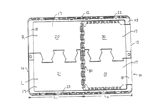
Fig. 1 is a plan view of the container constructed
according to an embodiment of the present invention with lids
constructed according to an embodiment of the present
invention shown in their closed position covering the open top
of the container;
Fig. 2 is a side elevation of the lidded container of
Fig. 1;
2159527
N-197
Fig. 3 is an end elevation of the lidded container shown
in Fig. 1;
Fig. 4 is a perspective view of the lids shown in Fig. 1
wherein the half lid pieces are shown in a partially opened
position;
Fig. 5 is an end elevation of the container shown in Fig.
1 without the lids and without the drop gate being attached to
the end wall;
Fig. 6 is a side view of the container shown in Fig. 1
without lids and without the drop gate;
Fig. 7 is a top plan view of the container shown in Fig.
1 without the lids and drop gate attached;
Fig. 8(a) is a detailed end elevational view of the
container, without lids, with the drop gate, as shown in Fig.
3, further shown with latches for securing the drop gate in
the closed position; Fig. 8(b) is a front elevational view of
the drop gate of Fig. 8(a) without the latches; and Fig. 8(c)
is a cross sectional view of the drop gate shown in Fig. 8(b)
taken along lines 8-8;
Fig. 9 is a side view of the latches shown in Fig. 8(a);
Fig. 10 is an elevational view of a drop gate according
to a modification of the embodiment shown in Fig. 8(a);
Fig. 11 is a top view of the drop gate shown in Fig. 10;
Fig. 12(a) is a plan view of the right full lid piece
shown in Fig. l; Figs. 12(b) and 12(c) are opposite side views
2159527
-
- N-197
of the lid piece shown in Fig. 12(a); and Fig. 12(d) is an end
view of the lid piece shown in Fig. 12(a);
Fig. 13(a) is a plan view of the left full lid piece
shown in Fig. 1; Figs. 13(b) and 13(c) are opposite side views
of the lid piece shown in Fig. 13(a); and Fig. 13(d) is an end
view of the lid piece shown in Fig. 13(a);
Fig. 14(a) is a plan view of the right half lid piece
shown in Fig. 1; Fig. 14(b) is a side view of the lid piece
shown in Fig. 14(a); and Fig. 14(c) is an end view, partly in
section, of the lid piece shown in Fig. 14(a);
Fig. 15(a) is a plan view of the left half lid piece
shown in Fig. l; Fig. 15(b) is a side view of the lid piece
shown in Fig. 15(a); and Fig. 15(c) is an end view, partly in
section, of the lid piece shown in Fig. 15(a);
Fig. 16(a) is a plan view of a hinge member used in
joining the full and half lid sections shown in Fig. 1; and
Fig. 16(b) is an end view of the hinge member shown in Fig.
16(a).
Detailed Descri~tion of the Preferred Embodiments
The invention is directed to a container having a drop
gate and also to lids for a container, optionally having a
drop gate.
Figs. 1-3 show a container 10 constructed according to an
embodiment of the present invention. The container has a
bottom wall 11, opposite side walls 12 and 13, opposite end
2159527
N-197
walls 14 and 15 connected together and extending upwardly to
form an open top. The top is covered by right and left lids,
designated R and L, respectively. Lids R and L are hinged to
side walls 12 and 13, respectively. In the open position, the
lids hang down in overlapping relation with the respective
side walls and in the closed position, shown in Fig. 1, the
lids are interlocked through a series of fingers and pockets.
A container having two lids is known as a tote box, or a
distribution tote. In the closed position of the lids, the
containers can be stacked on one another several high without
damaging the goods contained therein. When the containers are
empty, they can be stacked together in nested relation with
the lids fully opened.
According to the present invention, lids R and L are not
formed in single pieces. Rather, lid R is formed of a full
lid piece 20 and a half lid piece 30. Similarly, lid piece L
is also formed of a full lid piece 21 and a half lid piece 31.
The right and left side lid pieces differ in construction, but
are similar in detail. As shown, lid half 30 of lid R is
hinged to full lid 20, and likewise half lid 31 is hinged to
the full lid piece 21.
Conventional distribution totes are well known, and
typically have lids hinged to the side walls that are
rotatable about the respective hinge joints approximately 270
between the fully closed position and an open position wherein
2l59527
N-197
the lids hang down along the side walls. When the full and
half lid pieces 20, 30 and 21, 31 are fixed in substantially
coplanar relation with each other, as shown in Fig. 1, lids R
and L operate in a manner similar to a conventional
distribution tote by permitting the lids to be rotated
approximately 270 about respective hinge joints 22 and 23.
According to the invention, however, as shown in Fig. 4, half
lid pieces 30, 31 can be rotated about their respective hinge
joints approximately 180 (not shown) to permit one end of the
container to be opened without moving the lids with respect to
hinge joints 22 and 23. This permits access to the interior
of the container 10 without opening the lids in the
conventional manner.
Further, in accordance with the invention, as shown in
Figs. 2 and 3, one end wall 15 is provided with a drop gate 40
that can swing between the fully closed position shown in Fig.
3 to the open position shown in Fig. 2, wherein the drop gate
40 hangs down to overlap end wall 15. Drop gate 40 is
provided at the end of the container where half lids 30, 31
can be opened. By opening drop gate and half lids 30, 31 the
lidded container of the invention is suitable for use in a
flow racking system as a shelf box or hopper from which goods
can be selected in an order picking operation.
As shown in Fig. 1, lid halves 30, 31 have an overall
side to side dimension that is less than the side to side
21S9527
N-197
dimension of full lid pieces 20, 21 and that is preferably
about the same as the width of the recessed portion 17 of the
lids. Further, the length dimension (L2) of the lid pieces
30, 31 is lesslthan that (L1) of the lid pieces 20, 21. By
this arrangement, the half lid pieces 30, 31 can be rotated
approximately 180 to a position, not shown, wherein the half
lid pieces are substantially overlapping full lid pieces 20,
21 and wherein the overlap is confined within the recessed
portion 17 of the lid pieces 20, 21. As a result, one half of
container 10 can be opened without substantially increasing
the overall vertical dimension of the container. This is an
important consideration when using the container in a flow
racking system wherein maximum vertical density is required to
insure system efficiency. Also, maximum horizontal racking
density can be achieved when the container is opened without
increasing the width wise dimension of the container, which
would result if a conventional distribution tote were opened
to gain access to the interior of the container, i.e. with the
lids hanging down along the side walls of the container.
The drop gate 40, which is included in the preferred
embodiment, provides greater access through an opening 50,
shown in Fig. 5, in the container end wall 15. Further,
although the end wall to end wall dimension is increased by
opening the drop gate 40, the increase in dimension is not
significant since it doesn't affect the vertical or horizontal
21$9~27
N-197
dimensions, which are critical to achieving maximum flow
racking density.
Fig. 5 shows an end view from end wall 15 of the
preferred embodiment of the container constructed according to
the present invention. Fig. 6 shows a side view thereof,
without the lids attached. As shown in these figures, hinge
pin supports 51 are molded into end wall 15 along the bottom
edge 52 of opening 50. The sides 53 and 54 of the opening 50
have reinforcement flanges 55 and 56, respectively. Also,
pockets 57 and 58 are provided that are adapted to receive a
latch component of drop gate 40, as will be explained in
greater detail hereinafter. The axis 45 of the hinge pin is
shown in Fig. 7 and projects outwardly far enough away from
the end wall to permit 180 rotation of the drop gate.
For nesting, the end wall 14 has a plurality of nesting
stops 59, only one of which is shown, that engage with a top
flange area 60. Further, the side walls have nesting stops 61
and 62 along side wall 13, as shown in Fig. 6, and similar
nesting stops on opposite side wall 12, as shown in Fig. 5.
Nesting stops 61 and 62 engage flats 63 and 64 formed on top
of the hinge pin supports and flats 65 and 66 formed on
opposite hinge pin supports on side wall 12, respectively, as
shown in Fig. 7 Since the top edge of flats 63 and 64 are
shown along side wall 13 (Fig. 6) to be raised with respect to
top flange 60, nesting stops 61 and 62 are similarly raised
2159527
N-197
with respect to nesting stops 59 so that the nesting depth is
even. At the end wall 15, nesting stops are not provided so
that nesting can occur whether or not drop gate 40 is open or
closed. Further, as shown in Fig. 7, reinforcing ribs 67, 68
in the side walls of the container are tapered with respect to
one another for guiding containers into a nested stack.
Fig. 8(a) is a detailed view, similar to Fig. 3, showing
the drop gate 40 hinged to opening 50 in side wall 15 of
container 10. As shown in Fig. 8(a), the drop gate 40 is
retained in the fully closed position by latches 70 having
protrusions 71 that respectively engage the pockets 57, 58
formed in sides 53, 54 of the opening 50. Latches 70 are
received in latch receiving areas 41, as shown in Fig. 8(b).
The latches are resiliently urged outwardly and can be urged
inwardly to slide projections 71 out of pockets 57, 58 for
lowering the drop gate. For handling of the container by the
end walls, drop gate 40 also has a handle 44 molded in the lid
portion thereof, particularly as shown in Fig. 8(c). Further,
drop gate 40 has hinge pin supports 45a that engage with hinge
pin supports 51 for receiving therein the hinge pin, not
shown.
Fig. 9 shows an edge view of latch 70. A finger/thumb
hole 72 is provided for operation of the latch and is
connected to a bowed plastic member 73 that provides a
predetermined resilient force in the direction tending to
12
- 21$9527
N-197
maintain projection 71 in the respective pockets 57 and 58 of
the end wall 15. The tips of the projection 71 are angled to
guide the projection over the edge of the pockets during
closing of the drop gate. Opposite end 74 of latch 70 is "T"
shaped, as shown in Fig. 8(a), and is thereby held in place in
the latch receiving area 41 of the drop gate. Additionally,
drop gate 40 has outwardly spaced return flanges 47 and 48,
respectively, that overlap the reinforcing flanges 55 and 56,
shown in Fig. 5. These flanges protect the projections 71
from being damaged during operation of the drop gate.
Fig. 10 shows a modification to the drop gate
construction shown in Fig. 8(b). Whereas the drop gate of
Fig. 8(b) requires latches 70 to maintain the drop gate in the
fully closed position, drop gate 40' shown in Fig. 10 has
built in resilient flanges 49a and 49b that depend from the
sides of the drop gate in cantilevered fashion to provide the
resilience necessary to maintain the projections respectively
in pockets 56 and 57. Fig. 11 shows a top view of the drop
gate constructed according to Fig. 10, the details of which
are the same as drop gate 40 shown in Fig. 8(b), with the
exception of the projections 49a and 49b.
As shown in Fig. 1, lids R and L are attached by hinges
22 and 23 to side walls 12 and 13, respectively. Figs. 12(a)-
12(d) show detailed views of the full lid piece 20 of lid R.
Hinge pin supports 101, the details of which are shown in
21sss27
N-197
section in Fig. 12(c), are molded along the hinged end 102 of
full lid piece 20. Hinge pin supports 101 extend the full
length of the lid piece adjacent side wall 12 and mate with
corresponding hinge pin supports at the upper end of the side
wall 12, in a conventional manner to form a hinge axis lOla.
A main top portion 103 extends outwardly from hinged end 102
to cover one quarter of the open top of container 10. At the
free end 104 opposite hinged end 102, fingers 105 and recesses
106 (including half recesses 107 and 108) are provided that
mate with corresponding structure in full lid piece 21 of lid
L when the lids are closed. The fingers 105 have a wedge
shaped end 109 that mates in a correspondingly shaped part of
a recess. In addition, upstanding ribs or flanges 110 are
provided in the recesses to engage the terminal portions of
the fingers. This prevents separation between engaging
fingers and recesses when a load is placed on the lids in
their fully closed position.
Adjacent main top portion 103 and extending into the area
of the open top of container 10 is a support flange 111 that
provides side support for a free end 132 (Fig. 14(a) of
adjacent half lid piece 30. Along the sides of lid piece 20
are return flanges 112 and 113, respectively. Return flange
113 provides additional support to support flange 111 to
prevent bending. The portion of lid piece 20 that steps down
from return flanges 112 and 113, and from the hinge pin
14
2159527
.
N-197
supports 101, forms the recessed portion 17 of the lid, as
shown in Fig. 12(b). As shown in Fig. 12(d), the support
flange 11 is recessed with respect to recessed portion 17 by
the thickness of the lid piece 30 to make the recessed portion
17 uniform across both lid pieces 20 and 30 when they are
joined together in a closed position.
Half lid piece 30 is hinged to full lid piece 20 by a
hinge member 80 having a first pin that passes through hinge
pin supports 114 along a first hinge axis 114a shown in Figs.
12(a) and 12(b). Along support flange 111 are formed pocket
structures 115a that receive correspondingly formed post
structures 115b, as shown in Fig. 4, in half lid piece 30.
These engaging post and pocket structures prevent separation
between the half lid piece 30 and the support flange 111 when
a load is placed on the lids, for example during stacking.
Alternatively, as shown in Fig 1, the post and pocket
structure can be replaced with interlocking rib and groove
structure in order to achieve the same function, according to
a preferred embodiment.
Fig. 4 shows that hinge member 80 is used between the
full lid pieces and the half lid pieces to provide two hinge
pins for connecting the lid pieces. This allows 180 rotation
of lid piece 30, including movement of the hinge axis passing
through half lid piece 30 to be achieved so that it lays as
2I59527
N-197
flat as possible on lid piece 20 when folded back to an open
position.
Figs. 16(a) and 16(b) show a plan view and end view,
respectively, of hinge member 80 that is used to join the
respective hinge supports of lid pieces 20 and 30, and also
lid pieces 21 and 31. The hinge member permits two side by
side hinge pins to be used in forming the hinge joint between
the respective full and half lid pieces.
Figs. 14(a)-14(c) show the half lid piece 30 in detail.
In particular, lid piece 30 has fingers 117, a recess 118, a
half recess portion 119 and ribs 127 in the recesses. Half
recess portions 108 and 119 together form a full recess that
spans the hinge joint between the full and half lid pieces.
The fingers and recesses of both lid pieces 20, 30 work
together with corresponding structure formed in lid pieces 21,
31 to enable the free ends (opposite the hinged ends) of the
lids to be closed in engagement with each other.
The hinged end of lid half piece 30 has hinge pin
supports 120a-120d forming a second hinge axis 128 (in
addition to hinge axis 114a). Hinge pin support 120a has an
outer periphery that is semicircular, as shown by a dashed
line in Fig. 14(b), that is adapted to be received in a hinge
pin support recess 125 formed in lid piece 20 as shown in Fig.
12(a) and 12(b). This combination of structure provides
smooth rotation between the opened and closed positions of the
16
2159527
_,
N-197
half lid piece 30, which is required because of the
intermediate hinge member 80.
In the closed position, main top portion 103 of lid piece
20 is coplanar with lid portion 121 of lid piece 30. As shown
in Fig. 14(c), a pair of dependent flanges 122 extend
downwardly from the side edge of lid piece 30 to engage a
through hole 116 to provide a snap fit that secures lid piece
30 into engagement with support flange 111 of lid piece 20.
When the two pieces 20, 30 are snap fit together, the lid
pieces work together to open and close like a conventional
tote lid. In the closed position, a return flange 123 of lid
piece 30 functions like return flange 112 of lid piece 20 to
overlap the upper end 149 of drop gate 40. Additionally, as
shown in Figs. 14(a) and 14(c), a security tie aperture 124 is
provided in alignment with a similarly formed aperture in
upper end 149 of drop gate 40.
In Figs. 13(a)-13(d), the full lid piece 21 of lid L is
shown in detail and in Figs. 15(a)-15(c), the half lid piece
31 is shown in detail. The structure shown in these figures
that is in common with Figs. 12(a)-12(d) and 14(a)-14(c),
respectively, is shown with common reference numbers. The
main difference between the lid pieces 20 and 21 is that they
are in mirror image of one another. Further, lid piece 21 has
a one half finger portion 201 that engages the one half recess
portion 108 on one side of the hinge joint between lid pieces
2159527
N-197
21 and 31. Another one half finger piece 202 is formed in lid
piece 31 that engages the similarly shaped recess 119 in lid
piece 30. The combination of one half finger pieces 201, 202
and similarly shaped one half recesses or pockets 108 and 119
provide a strong support for the mid expanse of the lids R and
L. Thus, although each lid R and L have a hinge joint
extending across the lid, the lid has structural integrity and
can withstand stacking loads placed on the lids, normally
encountered when several of the containers with their lids in
the closed position are stacked on one another. Also provided
in full lid piece 21 is a aperture 130 that is adapted to
receive a security tie, for example.
Although the present invention has been described with
respect to the combination of container and lids, the lids can
be used with containers of standard totes that do not have a
drop gate 40. Use of a container having a drop gate, however,
is preferred because greater access can be gained to the
interior of the container with the drop gate opened and the
half lid pieces folded back to their opened position. This
makes the container useful as a shelf box in a flow rack
system.
The combination of container and lid according to the
present invention is also useful as a standard distribution
tote for shipping orders filled at the distribution center to
retail outlets. At the retail outlets, the container can then
18
2I59527
_
N-197
be opened and used in the same way as standard distribution
totes, for displaying merchandise, or removing merchandise and
displaying the merchandise on shelves.
In a preferred embodiment of the invention, the container
can also be used to replace the bulk shipping containers used
by suppliers and vendors to ship goods to a distribution
center. In this way, goods to be selected in a flow racking
or order picking system can be received at the distribution
center in the containers, and the containers can be opened to
the extent that the half lid pieces are folded back to their
open position overlaying the full lid pieces, and with the
drop gates of the containers opened, the combined container
and lids of the invention can be used as shelf boxes directly
without unpacking the goods as they are received from the
suppliers or vendors. Then, once the orders are selected, the
container can be used for shipping the selected goods to the
retail outlets. In this way, the distribution system from
supplier to retail outlet is managed using only one container,
in three different ways.
Preferably, the container and lids, including the lid
pieces and hinge members, are all molded of plastic by
injection molding the individual pieces, as shown in the
figures. Accordingly, assembly of the container with the lids
requires inserting the hinge pins through the respective hinge
pin supports and inserting the optional latch members in the
- 2159S27
_
N-197
drop gate. Thus, an economical container with lids serving
many functions can be constructed according to the invention
with a minimum amount of labor cost occurred in the assembly
of the container and lids.
Although preferred embodiments of the invention have been
disclosed in the foregoing description of the invention, other
modifications are possible and would be known to those having
ordinary skill in the art. Additionally, further
modifications, additions and alterations are included within
the scope of the invention, as defined in the claims.