Note: Descriptions are shown in the official language in which they were submitted.
211 59585
-
COEXTRUDED THREE-DIMENSIONAL
FLUID-PERVIOUS PLASTIC WEB
TECHNICAL FIELD
The present invention relates to resilient, three-dimensional fluid-
pervious, plastic webs for use as topsheets on absorbent articles, especially
catamenial articles, and more particularly, to such webs including a first
polymeric material and a second polymeric material secured together to form a
l~min~te. The first polymeric material exhibits a melting point temperature
greater than the melting point temperature of the second polymeric material suchthat when the three-dimensional web is heated to a temperature between the firstmelting point temperature and the second melting point temperature the second
polymeric material is thermally bonded to the underlying layer of the absorbent
article, e.g., the absorbent core.
BACKGROUND OF THE INVENTION
It has long been known in the disposable absorbent bandage art that it is
extremely desirable to construct absorptive devices such as disposable diapers,
catamenials, sanitary napkins, incontinent articles, and the like presenting a dry
surface feel to the user to improve wearing comfort and to minimi~e the
development of undesirable skin conditions due to prolonged exposure to
moisture absorbed within the bandage.
One viable prior art solution to the aforementioned problem is disclosed
in commonly 2csi~n~d U.S. Patent 4,342,314 issued to Radel and Thompson on
August 3, 1982. Radel et al. discloses an absorbent bandage with a wearer-
contacting topsheet comprising a resilient macroscopically expanded, ~ree-
dimensional, plastic web exhibiting a combination of fiber-like and plastic
properties. In a preferred embodiment, the macroscopically expanded, three-
dimensional, plastic web topsheet disclosed in Radel et al. exhibits a fine scale
three-dimensional microstructure comprising capillary ori~in~ting in and
' r
' ~..
w o 94/22407 ~S95~ PCT~US94/0313t
extending from one s'urface of the web and terminating in the form of
apertures in the opposite surface thereof to promote rapid fluid
transport. The web's fiber-like appearance is comprised of a
continuum of fiber-like elements, the opposed ends of each of the
fiber-like elements are interconnected to at least one other of the
fiber-like elements.
A typical capillary network in the Radel et al. structure
comprises an uppermost capillary opening formed by a multiplicity of
primary fiber-elements interconnected to one another in the uppermost
plane of the web. The uppermost opening may, if desired, be further
subdivided into smaller capillary openings by secondary and tertiary
fiber-like elements at planes located below the wearer-contacting
surface of the web.
Each of the fiber-like elements exhibits a substantially uniform
U-shaped cross-section along its length. In the case of a primary
fiber-like element, its cross-séction comprises a base portion located
in the wearer-contacting plane and a sidewall portion joined to each
edge of the base portion, the sidewall portions extend generally in
the direction of the absorbent pad-contacting surface of the web. The
sidewall portions which intersect one another are joined to one
another intermediate the wearer contacting surface and the absorbent
pad contacting surface of the web, thereby forming a capillary network
interconnecting the opposed surfaces of the web. The secondary and
tertiary fiber-like elements, when employed, are generally similar,
but originate in planes below the wearer-contacting surface of the
web.
A topsheet of the type generally disclosed by Radel et al. is
highly effective in promoting rapid fluid transfer from the first
wearer-contacting surface to the second absorbent pad-contacting
surface of the topsheet. Accordingly, topsheets of this type have
enjoyed widespread commercial success on catamenial pads due to their
clean and dry appearance in use when contrasted to conventional
nonwoven fibrous topsheets. ~hile the Radel et al. topsheet is highly
effective in promoting rapid transfer of bodily fluids from the first
- 35 wearer-contacting surface to the second absorbent pad-contacting
surface, the topsheet is secured to the absorbent core with an
adhesive. Unfortunately, adhesives have a tendency to clog the
94/22447 2 1 5-9 5 8 S P~rruss4/03132
_ 3
~ apertures if applied too heavily. If the apertures become clogged,
fluid is not permitted to drain through the topsheet thereby exposing
the skin to moisture. In addition, bonding layers together with an
adhesive to ensure fluid transporting contact throughout can produce a
stiff structure which is uncomfortable. Furthermore, adhesives may
not provide sufficient contact between the topsheet and the underlying
layers if applied too sparingly or may be rendered useless when wetted
with body exudate.
Another prior art attempt at securing a topsheet to the
underlying l-ayer is disclosed in U.S. Pat. Nos. 4,690,679 issued
September 1, 1989 and 4,806,411 issued February 21, 1989 to Mattingly,
III et al. Both of these patents disclose a coextruded, apertured,
two-dimensional film suitable for use as topsheet on a sanitary
napkin. The coextruded film comprises a f~rst layer of a first
polymeric material and a second layer of a second polymeric material.
Both layers are apertured for the transmission of bodily fluids
therethrough. The first polymeric material exhibits a melting point
temperature which is greater than the melting point temperature
exhibited by the second polymeric material. The apertured film may be
thermally bonded by heating the film to a temperature in excess of the
melting point temperature of the second layer material and below the
melting temperature of the first layer material. ~hile this
two-dimensional apertured film may be well suited for thermal bonding
it would not function well as a topsheet on an absorbent article.
Since the entire nonaperatured portion of the second polymeric
material will be thermally bonded to the underlying layer, e.g., the
absorbent core, a relatively stiff sanitary napkin will be created due
to the excessive amount of bonding between the topsheet and the
absorbent core. Furthermore, the two-dimensional topsheet does not
provide sufficlent standoff from the absorbent core for the wearer.
Accordingly, even as fluid is permitted to pass through the apertures
provided in the two-dimensional topsheet, the wearer's skin is placed
in intimate contact with the bodily fluids which have been absorbed by
the absorbent core.
-35 Accordingly, lt is desirable to provlde an absorbent article
having a topsheet sheet which may be thermally bonded to the absorbent
core and yet maintain the flexibility, resllience, and standoff of the
''- 2~9~85
' ._
prior art commercially successful three-dimensional formed-film topsheets.
SUMMARY OF THE INVENTION
The present invention pertains, in a prefelled embodiment, to an
absorbent article including a fluid pervious topsheet, a fluid impervious
backsheet joined to the topsheet, and an intermediate layer positioned between
the topsheet and the b~ck~heet. The topsheet comprises, a resilient, three-
dimensional, macroscopically expanded, fluid pervious web including a first
polymeric material which exhibits a first melting point temperature and a
second polymeric material bonded to the first polymeric material to form a
l~min~te. The second polymeric material exhibits a melting point temperature
which is less than the first melting point temperature. The web has first and
second surfaces spaced apart by a distance greater than the thickness of the
l~min~te. The web has a plurality of capillaries extending from the first
surface to the second surface. The capillaries are defined by a plurality of
sidewall portions interconn~cte~l to one another intermediate the first and
second surfaces and terminate in the second surface, such that when the web is
heated to a temperature between the first melting point temperature and the
second melting point temperature the second polymeric material of the sidewall
thermally bonds to the intermediate layer.
Other aspects of this invention are as follows:
An absorbent article including a fluid pervious topsheet, a fluid
impervious backsheet joined to said topsheet, and an intermediate layer
positioned between said topsheet and said backsheet, said topsheet comprising:
a resilient, three-dimensional, macroscopically expanded, apertured, fluid
pervious web including a first polymeric film material which exhibits a first
melting point temperature and a second polymeric film material bonded to said
first polymeric material to form a l~rnin~te, said l~rnin~te having a thickness, said
second polymeric material exhibits a melting point temperature which is less
than said first melting point temperature, said web having first and second
4a ~ 9 5 8 5
',_
surfaces spaced apart by a distance greater than the thickness of said l~qmin~te,
said web having a plurality of capillaries extending from said first surface to said
second surface, said capillaries being defined by a plurality of sidewall portions
interconnected to one another intermediate said first and said second surfaces
5 and tçrrnin~ting in said second surface, such that when said web is heated to a
temperature between said first melting point tempc.dlule and said second meltingpoint temperature said second polymeric material of said sidewall thermally
bonds to said intermediate layer.
An absorbent article including a fluid pervious topsheet, a fluid
10 impervious backsheet joined to said topsheet, and an intermediate layer
positioned between said topsheet and said backsheet, said topsheet comprising:
a resilient, three-dimensional, macroscopically expanded, apertured, fluid
pervious web including a first polymeric film material forming an uppermost
layer which exhibits a first melting point temperature and a second polymeric
15 film material forming a lowermost layer bonded to said first polymeric material
to form a l~min~te, said l~min~te having a thickness, said second polymeric
material exhibits a melting point temperature which is less than said first melting
point temperature, said web having first and second surfaces spaced apart by a
distance greater than the thickness of said l~min~te, said web having a plurality
20 of capillaries extending from said first surface to said second surface, saidcapillaries being defined by a plurality of sidewall portions interconnected to one
another intermediate said first and said second surfaces and terrnin~ting in said
second surface, such that when said web is heated to a temperature between said
first melting point temperature and said second melting point temperature said
25 lowermost layer thermally bonds to said intermediate layer.
An absorbent article including a fluid pervious topsheet, a fluid
impervious backsheet joined to said topsheet, and an intermediate layer
positioned between said topsheet and said backsheet, said topsheet comprising:
~ .B
_ 4b ~ ~ 5 9 5 ~ 5
a resilient, three-dimensional, macroscopically exr~ntlerl~ apertured, fluid
pervious web including a first polymeric film material forming a lowermost layerwhich exhibits a first melting point tempeldlule and a second polymeric film
material forming an uppermost layer bonded to said first polymeric material to
5 form a l~min~te, said l~min~te having a thickness, said second polymeric
material exhibits a melting point telll~e.dl~lre which is less than said first melting
point temperature, said web having first and second surfaces spaced apart by a
distance greater than the thickness of said l~min~te, said web having a plurality
of capillaries exten-lin~ from said first surface to said second surface, said
10 capillaries being defined by a plurality of sidewall portions interconnected to one
another intermediate said first and said second surfaces and tçrmin~ting in saidsecond surface, such that when said web is heated to a temperature between said
first melting point temperature and said second melting point temperature said
uppermost layer thermally bonds to said intçrmediate layer.
BRIEF DESCRIPTION OF THE DRAWINGS
While the specification concludes with claims particularly pointing out
and distinctly claiming the present invention, it is believed that the present
invention will be better understood from the following description in conjunction
with the accompanying drawings, in which like reference numbers identify
identical elements and wherein:
Figure 1 is a top plan view of a sanitary napkin with portions cut-away to
more clearly show the construction of the sanitary napkin;
Figure 2 is a cross-sectional view of the sanitary napkin of Figure 1 taken
along line 2-2;
Figure 3 is an enlarged, partially segmented, perspective illustration of a
preferred resilient, three-dimensional,
, . .
-~ 94/22407 5 1S9s85 PCT/US94/03132
~- macroscopically expanded, fluid pervious, web of the present
invention;
Figure 4 is an enlarged, partially segmented, perspective
illustration of a photoetched laminate structure of the type used to
form the web illustrated in Figure 3;
Figure 5 is a schematic illustration of the assembly of sanitary
napkins;
Figure 6 is a cross-sectional view of another embodiment of a
sanitary napkin of the present invention;
Figure 7 is a cross-sectional view of another embodiment of a
sanitary napkin of the present invention;
Figure 8 is a cross-sectional view of a symmetrical ~Hn-shaped
capillary channel fiber with a planar base (4), with between walls
(5), and a depth-of-walls (6);
Figure 9 is a cross-sectional view of a ~C~-shaped capillary
channel fiber having stabilizing legs;
Figure 10 is a cross-sectional view of a multiple ~H~-shaped
capillary channel fiber;
Figure 11 is a cross-sectional view of a multiple ~U~-shaped
capillary channel fiber;
Figure 12A is a cross-sectional view of an ~H~-shaped capillary
channel fiber and.a partially collapsed state;
Figure 12B is a cross-sectional view of an expanded capillary
channel fiber;
Figure 12C is a cross-sectional view of a wholly collapsed
capillary channel fiber; and
Figure 13 is a photomicrograph (21.4x) of a structure which may
be utilized as an intermediate layer in the sanitary napkin of the
present invention.
DETAILED DESCRIPTION OF THE INVENTION
1. General Description of the Absorbent Article
As used herein, the term ~absorbent article~ refers to devices
which absorb and contain body exudates, and, more specifically, refers
.35 to devices which are placed against or in proximity to the body of the
wearer to absorb and contain the various exudates discharged from the
body. The term ~absorbent article~ is intended to include diapers,
WO 94/22407 2 'IS 9 5 85 6 PCT/US94/03132
catamenial pads, sanitary napkins, pantiliners, incontinent pads, and
the like. The term "disposable" is used herein to describe absorbent
articles which are not intended to be laundered or otherwise restored
or reused as an absorbent article (i.e., they are intended to be
discarded after a single use, and, preferably, to be recycled,
composted or otherwise disposed of in an environmentally compatible
manner). A ~unitary~ absorbent article refers to absorbent articles
which are formed of separate parts united together to form a
coordinated entity so that they do not require separate manipulative
parts like a separate holder and pad.
A preferred embodiment of a unitary disposable absorbent article
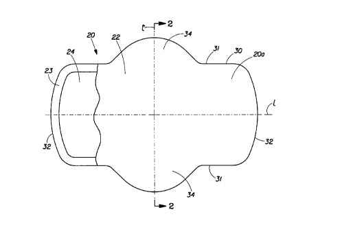
is the catamenial pad, sanitary napkin 20, shown in Fig. 1. As used
herein, the term ~sanitary napkin~ refers to an absorbent article
which is worn by females adjacent to the pudendal region, generally
external to the urogenital region, and which is intended to absorb and
contain menstrual fluids and other vaginal discharges from the
wearer's body (e.g., blood, menses, and urine). Interlabial devices
which reside partially within and partially external of the wearer's
vestibule are also within the scope of this invention. As used
herein, the term ~pudendal~ refers to the externally visible female
genitalia. It should be understood, however, that the present
invention is also applicable to other feminine hygiene or catamenial
pads such as pantiliners, or other absorbent articles such as
incontinence pads, and the like.
The sanitary napkin 20 has two surfaces, a wearer-contacting
surface or body-contacting surface or ~body surface~ 20a and a garment
surface 20b. The sanitary napkin 20 is shown in Fig. 1 as viewed from
its body surface 20a. The body surface 20a is intended to be worn
ad~acent to the body of the wearer. The garment surface 20b of the
sanitary napkin 20 (shown in Fig. 2) is on the opposite side and is
intended to be placed adjacent to the wearer's undergarments when the
sanitary napkin 20 is worn.
The sanitary napkin 20 has two centerlines, a longitudinal
centerline ~l~ and a transverse centerline ~t~. The term
- 35 ~longitudinal~, as used herein, refers to a line, axis or direction in
the plane of the sanitary napkin 20 that is generally aligned with
(e.g., approximately parallel to) a vertical plane which bisects a
' g4/22407 Z1s9s8s PCTlUSg4/03132
~ standing wearer into left and right body halves when the sanitary
napkin 20 is worn. The terms ~transverse" or Hlateral" as used
herein, are interchangeable, and refer to a line, axis or direction
which lies within the plane of the sanitary napkin 20 that is
~ 5 generally perpendicular to the longitudinal direction.
Figure 1 is a top plan view of the sanitary napkin 20 of the
present invention in its flat-out state with portions of the structure
being cut-away to more clearly show the construction of the sanitary
napkin 20 and with the portion of the sanitary napkin 20 which faces
or contacts the wearer 20a, oriented towards the viewer. As shown in
Fig. 1, the sanitary napkin 20 preferably comprises a liquid pervious
topsheet 22, a liquid impervious backsheet 23 joined with the topsheet
22, and an absorbent core 24 positioned between the topsheet 22 and
the backsheet 23.
Figure 1 also shows that the sanitary napkin 20 has a periphery
30 which is defined by the outer edges of the sanitary napkin 20 in
which the longitudinal edges (or ~side edges~) are designated 31 and
the end edges (or ~ends~) are designated 32.
Sanitary napkin 20 preferably includes optional side flaps or
~wings~ 34 that are folded around the crotch portion of the wearer's
panties. The side flaps 34 can serve a number of purposes, including,
but not limited to protecting the wearer's panties from soiling and
keeping the sanitary napkin secured to the wearer's panties.
Figure 2 is a cross-sectional view of the sanitary napkin 20
taken along section line 2-2 of Fig. 1. As can be seen in Fig. 2, the
sanitary napkin 20 preferably includes an adhesive fastening means 36
for attaching the sanitary napkin 20 to the undergarment of the
wearer. Removable release liners 37 cover the adhesive fastening
~eans 36 to keep the adhesive from sticking to a surface other than
the crotch portion of the undergarment prior to use.
In addition to having a longitudinal direction and a transverse
direction, the sanitary napkin 20 also has a ~z~ direction or axis,
which is the direction proceeding down through the topsheet 22 and
into whatever fluid storage core 24 that may be provided. The
ob~ective is to provide a continuous path between the topsheet 22 and
underlying layer or layers of the articles herein, such that fluid is
eventually drawn in the ~z~ direction and away from the topsheet of
w o 94122407 2159S8 PCT/US94/03132
the article into its ultimate storage layer. In a preferred
embodiment the continuous path will have a gradient of increasing
capillary attraction which facilitates fluid flow down into the
storage medium.
The individual components of the sanitary napkin will now be
looked at in greater detail.
2. Individual Components of the SanitarY NaDkin
A. The ToDsheet
Figure 3 is an enlarged partially segmented, perspective
illustration of a preferred embodiment of a resilient,
three-dimensional, macroscopically expanded, fluid pervious, plastic
web 10 which has been found suitable for use as a topsheet on
disposable absorbent articles, such as the sanitary napkin 20
illustrated in Figs. 1 and 2. As utilized herein, the term
~macroscopically expanded~, when used to describe three-dimensional
plastic webs, ribbons and films, refers to webs, ribbons and films
which have been caused to conform to the surface of a
three-dimensional forming structure so that both surfaces thereof
exhibit the three-dimensional pattern of said forming structure, said
pattern being readily visible to the naked eye when the perpendicular
distance between the viewer's eye and the plane of the web is about 12
inches. As can be seen in Fig. 3, the web 10 is comprised of a first
polymeric material 50 and a second polymeric material 52 secured to
the first polymeric material to form a laminate. Preferably the
laminate web 10 is formed by the coextrusion of two polymers. The
first polymeric material 50 exhibits a first melting point
te~perature. The second polymeric material 52 exhibits a second
melting point temperature which is less than the melting point
temperature of the first material 50. As used herein, the term
~melting point~ refers to the temperature at the peak of the melting
endotherm? at which point the solid and liquid states are in
equilibrium.
Preferably, the web 10 is comprised of a continuum of fiber-like
elements, the opposed ends of each of the fiber-like elements are
interconnected to at least one another of the fiber-like elements to
give the web 10 a fiber-like appearance. In the embodiment disclosed
in Fig. 3, the interconnected fiber-like elements form a pattern of
~~ 7 9 2 1 S g S 8 ~ P~r~us94l03l32
~ pentagonally shaped capillaries 40. The web 10, which exhibits a
fiber-like appearance, embodies a three-dimensional structure
comprising capillaries 40 extending from the web's uppermost or
wearer-contacting surface 41 in plane 42 to its lowermost or absorbent
pad contacting surface 43 in plane 44 to promote rapid fluid transport
from the uppermost surface 41 to the lowermost surface 43 of the web
10 without lateral transmission of fluid between adjacent capillaries
40.
Apertures 45 are formed by a multiplicity of intersecting
fiber-like elements, e.g., elements 46, 47, 48, 49, and 50,
interconnected to one another in the first surface of the web. Each
fiber-like element comprises a base portion, e.g., base portion 54,
located in plane 42. Each base portion has a sidewall portion, e.g.,
sidewall portions 55, attached to each edge thereof. The sidewall
portions 55 extend generally in the direction of the second surface 43
of the web. The intersecting sidewall portions of the fiber-like
elements are interconnected to one another intermediate the first and
second surfaces of the web and terminate substantially concurrently
with one another in the plane 44 of the second surface.
In a particularly preferred embodiment, the interconnected
sidewall portions terminate substantially concurrently with one
another in the plane of the second surface 44 to form apertures 39 in
the second surface 43 of the web. The capillaries 40 formed by the
interconnected sidewall portions allow for free transfer of fluids
from the first surface 41 of the web directly to the second surface 43
of the web without lateral transmission of the fluid between adjacent
caplllary networks.
Preferably, the web 10 is formed by the coextrusion of two
polymers. The polymers used for top layer 50 and bottom layer 52
should both be flexible. In addition, the two polymers chosen should
have adequate strength to withstand the normal wear and tear expected
when used as a topsheet on an absorbent article.
The main criterion for selecting the polymers to be used for the
uppermost layer 50 and the lowermost layer 52 is the melting point
temperature dlfferential between any two possible polymers. Once a
poly~er for one layer is selected, the polymer for the other layer can
be chosen such that the polymer of the uppermost layer 50 has a higher
WO 94/22407 ' . '~ PCTIUS94/03132
2,1'5'gS~S 10
melting point temperature than that of the lowermost layer 52. rne
melting point temperature of the lowermost layer 52 should be matched
with the thermal bonding component of the intermediate layer of the
sanitary napkin.
Suitable polymers for the uppermost layer 50 include low density
polyethylene (LDPE), medium density polyethylene (MDPE), high density
polyethylene (HDPE), linear low density polyethylene (LLDPE),
polypropylene and blends thereof. Suitable polymers or materials for
the lowermost layer 52 include polymers bondable to the materials used
for uppermost layer 50 above, but of lower melting point temperature,
ethylene vinyl acetate (EVA) and blends thereof. In a particularly
preferred embodiment, the uppermost layer 50 comprises a LDPE/LLDPE
blend and the lowermost layer 52 comprises a blend of LDPE/EVA.
In another embodiment, the melting point temperature of the
uppermost layer is less than the melting point temperature of the
lowermost layer. As with the previous embodiment, the main criterion
for selecting the polymers to be used for the uppermost and lowermost
layers is the melting point temperature differential between any two
possible polymers. Once a polymer for one layer is selected, the
polymer for the other layer can be chosen such that the polymer of the
uppermost layer has a lower melting point temperature than that of the
lowermost layer.
B. The Absorbent Core
The absorbent core 24 may be any absorbent means which is capable
of absorbing or retaining liquids (e.g., menses and/or urine). As
shown in Figs. 1 and 2, the absorbent core 24 has a body surface, a
garment surface, side edges, and end edges. The absorbent core 24 may
be manufactured in wide variety of sizes and shapes (e.g.,
rectangular, oval, hourglass, dog bone, asymmetric, etc.) and from a
wide varlety of liquid-absorbent materials commonly used in sanitary
napkins and other absorbent articles such as comminuted wood pulp
which is generally referred to as airfelt. An example of other
suitable absorbent materials include creped cellulose wadding;
meltblown polymers including coform; chemically stiffened, modified or
cross-linked cellulosic fibers; capillary channel fibers; synthetic
fibers such as crimped polyester fibers; peat moss; tissue including
tissue wraps and tissue laminates; absorbent foams; absorbent sponges;
159~8~
superabsorbent polymer; absorbent gelling materials; or any equivalent material
or combinations of materials, or mixtures of these.
The configuration and construction of the absorbent core 24 may also be
varied (e.g., the absorbent core may have varying caliper zones (e.g., profiled
so as to be thicker in the center), hydrophilic gradients, superabsorbent
gradients, or lower density and lower average basis weight acquisition zones; ormay comprise one or more layers or structures). The total absorbent capacity of
the absorbent core 24 should, however, be compatible with the design loading
and the intended use of the sanitary napkin 20. Further, the size and absorbent
capacity of the absorbent core 24 may be varied to accommodate different uses
such as incontinence pads, pantiliners, regular sanitary napkins, or overnight
sanitary napkins.
Exemplary absorbent structures for use as the absorbent core 24 of the
present invention are described in U.S. Patent 4,950,264 issued to Osborne on
August 21, 1990; U.S. Patent 4,610,678 issued to Weisman et al. on September
9, 1986; U.S. Patent 4,834,735 issued to Alemany et al. on May 30, 1989; U.S.
Patent 5,009,653 issued to Osborne on April 23, 1991; and European Patent
Application No. 0 198 683, The Proctor & Gamble Company, published
October 22, 1986 in the name of Duenk et al.
A preferred embodiment of the absorbent core 24 comprises the l~Tnin~te
structure shown in Fig. 2. The l~min~te is comprised of a layer of
superabsorbent polymeric (or absorbent gelling material) and one or more
sheets or webs of cross-linked cellulosic fibers. Suitable cross-linked cellulosic
fibers for the absorbent core 24 are described in U.S. Patent 4,888,093 issued to
Cook et al. on December 19, 1989; U.S. Patent 4,822,543 issued to Dean et al.
on April 18, 1989; U.S. Patent 4,889,595 issued to Schoggen et al. on
December 26, 1989; and U.S. Patent 4,898,642 issued to Moore et al. on
February 6, 1990; U.S. Patent 4,935,022 issued June 19, 1990 to Lash et al.;
EPO Patent Application Publication Nos. 0 427 316 A2 and 0 427 317 A2
published in the name of Herron et al. on May 15, 1991; and EPO Patent
Application Publication No. 0 429 112 A2 published in the name of Herron et
al. on May 29, 1991.
59~~ o s4t22407 F~r~USs4/03132 __
12
The cross-linked cellulosic fibers in the embodiment shown ln
Fig. 2 comprises a single sheet that wraps the layers of particles of
absorbent gelling material 60. The sheet is wrapped so that it
appears as having a ~c" configuration when viewed from the end. The
wrapped sheet forms an upper layer 61 and a lower layer 62. In
alternative embodiments, the laminate can be formed in many other
manners, such as by providing separate webs of cross-linked cellulosic
material (or other absorbent material) for the different layers of the
absorbent core laminate other than a single sheet, or by providing it
with additional layers.
In this type of core, curled, twisted, preferably chemically
stiffened and cross-linked, cellulose fibers are refined to provide
fibers which can be used in sheet form as the absorbent core. The
preparation of suitable curled, chemically stiffened cellulosic fibers
from which one can prepare the refined, curled, chemically stiffened
cellulosic fibers used in detail in U.S. Patents 4,888,903; 4,822,543i
4,889,595; 4,889,597; 4,889,596; and 4,898,642.
The use of such fibers in combination with absorbent gelling
materials, and means for manufacturing such combinations, are
described in U.S. Patent 4,935,022. Such preparations typically
involve the use of aldehydes, such as glutaraldehyde, as crosslinking
agents. In addition, polycarboxylic acids can be used as crosslinking
agents. It will be appreciated that other means for preparing other
crosslinked cellulosic fibers are also known, and such fibers may also
be used herein, although the fluid absorbency properties may be
suboptimal as compared with the above-mentioned fibers. Reference can
be made to the various citations in U.S. Patent 4,898,642 and PCT U.S.
89 01581 for other fiber types. Once in hand, the curled cellulosic
fibers are refined to provide the fibers used to prepare the preferred
absorbent cores used in the practice of this invention.
C. Backsheet
The backsheet 23 is impervious to liquids (e.g., menses and/or
urine) and is preferably manufactured from a thin plastic fil~,
although other flexible liquid impervious materials may also be used.
As used herein, the term ~flexible~ refers to materials which are
compliant and will readily conform to the general shape and contours
of the human body. The backsheet 23 prevents the exudates absorbed
13
~ 59~5
and contained in the absorbent core 24 from wetting articles which contact the
sanitary napkin 20 such as pants, pajamas and undergarments. The backsheet 23
may thus comprise a woven or nonwoven material, polymeric films such as
thermoplastic f1lms of polyethylene or polypropylene, or composite materials
5 such as a film-coated nonwoven material. Preferably, the backsheet is a
polyethylene film having a thickness of from about 0.012 mm (0.5 mil) to about
0.051 mm (2.0 mils). Exemplary polyethylene films are manufactured by
Clopay Corporation of Cincinnati, Ohio, under the designation P18-0401 and by
Ethyl Corporation, Visqueen Division, of Terre Haute, Indiana, under the
10 designation XP-39385. The backsheet 23 is preferably embossed and/or matte
finished to provide a more clothlike appearance. Further the backsheet 23 may
permit vapors to escape from the absorbent core 24 (i.e., breathable) while still
preventing exudates from passing through backsheet 23.
D. Optional Retaining Means
In use, the sanitary napkin 20 can be held in place by any support means
or attachment means well-known for such purposes. Preferably, the sanitary
napkin is placed in the user's undergarment or panty and secured thereto by a
fastener such as an adhesive 36. The adhesive 36 provides a means for securing
the sanitary napkin 20 in the crotch portion of the panty. Thus, a portion or all of
20 the outer surface of the backsheet 23 is coated with adhesive. Any adhesive or
glue used in the art for such purposes can be used for the adhesive herein, withpressure-sensitive adhesives being preferred. Suitable adhesives are Century A-
305-IVTM manufactured by the Century Adhesives Corporation of Columbus,
Ohio; and Instant Lock 34-2823TM manufactured by the national Starch and
25 Chemical Company of Bridgewater, New Jersey. Suitable adhesive fasteners are
also described in U.S. Patent 4,917,697. Before the sanitary napkin is placed inuse, the pressure-sensitive adhesive 36 is typically covered with a removable
release liner 37 in order to keep the adhesive 36 from drying out or adhering to a
surface other than the crotch portion of the panty prior to use. Suitable release
30 liners 37 are also described in the above-referenced U.S. Patent 4,917,697. Any
commercially available release liners commonly used for such purposes can be
utilized herein. Non-limiting examples of suitable release
. . ,~
14 ~ 5 9 ~ ~ ~
liners are BL30MG-A Silox E1/0TM and BL30MG-A Silox 4p/0TM both of which
are manufactured by the Akrosil Corporation of Menasha, Wisconsin. The
sanitary napkin 20 of the present invention is used by removing the release liner
37 and thereafter placing the sanitary napkin 20 in a panty so that the adhesive36 contacts the panty. The adhesive 36 m~in~in~ the sanitary napkin in its
position within the panty during use.
E. Optional Features
The sanitary napkin 20 may also be provided with two flaps 34, each of
which are adjacent to and extend laterally from the side edge of the absorbent
core. The flaps 34 are configured to drape over the edges ofthe wearer's pantiesin the crotch region so that the flaps 34 are disposed between the edges of the
wearer's panties and the thighs.
The flaps 34 serve at least two purposes. First, the flaps 34 help serve to
prevent soiling of the wearer's body and panties by menstrual fluid, preferably
- 15 by forming a double wall barrier along the edges of the panties. Second, the
flaps 34 are preferably provided with ~ çhment means on their garments
surface so that the flaps 34 can be folded back under the panty and attached to
garment facing side ofthe panty. In this way, the flaps 34 serve to keep the
sanitary napkin 20 properly positioned in the panty.
The flaps 34 can be constructed of various materials including materials
similar to the topsheet, backsheet, tissue, or combinations of these materials.
Further, the flaps 34 may be a separate element attached to the main body
portion of the napkin or can comprise extensions of the topsheet 22 and the
backsheet 23 (i.e., unitary).
A number of sanitary napkins having flaps suitable or adaptable for use
with the sanitary napkins of the present invention are disclosed in U.S. Patent
4,687,478 entitled "Shaped Sanitary Napkin with Flaps", issued to Van Tilburg
on August 18, 1987; U.S. Patent 4,589,876 entitled "Sanitary Napkin", issued to
Van Tilburg on May 20, 1986; and U.S. Patent 4,608,047, entitled "Sanitary
Napkin Attachment Means", issued to Medingly on August 26, 1986.
F. Optional Layers
Referring now to Figure 6, another embodiment of a sanitary napkin 200
is illustrated. The sanitary napkin 200 has a body surface
' ~
~ 94/22407 1S9S8S PCT/US94tO3132
'._
200a and a garment surface 200b. The sanitary napkin 200 comprises a
liquid pervious topsheet 222, a liquid impervious backsheet 223, an
absorbent core 224, side flaps 234, an adhesive fastening means 236
and removable release liners 237.
Sanitary napkin 200 can also be provid~d with one or more
additional layers or components. These include an acquisition layer
(or the ~secondary topsheet~) 201 positioned generally between the
topsheet 222 and the absorbent core 224. The sanitary napkin 200 may
also include a nonwoven layer 202 positioned between the absorbent
10 core 224 and the backsheet 223. The nonwoven layer 202 serves to keep
the material of the core 224 from tearing (when the core is comprised
of cross-linked cellulose fibers) and the layers of the sanitary
napkin 200 are stitched together.
Secondary topsheet 201, absorbent core 224, and nonwoven 202 are
15 all intermediate the topsheet 222 and the backsheet 223. Depending
upon the desired characteristics for the sanitary napkin 200, one or
more of these intermediate layers may be provided in a sanitary
napkin. In addition, there are other materials and components which
may serve useful as an intermediate layer between the topsheet 222 and
the backsheet 223 to provide the desired characteristics, e.g., fluid
movement, storage capacity, fluid acquisition, fluid distribution,
resilience, flexibility, thickness, or any combination of the above.
It will be obvious to one skilled in the art that the intermediate
layer, the layer between the topsheet 222 and the absorbent core 223,
may be any layer or layers which serves to provide specific functions
for the sanitary napkin 200.
Referring now to Figure 7 another embodiment of a sanitary napkin
300 is illustrated. The sanitary napkin 300 has a body surface 300a
and a gar~ent surface 300b. The sanitary napkin 300 comprises a
liquid pervious topsheet 322, a liquid impervious backsheet 323, an
absorbent core 324, side flaps 334, adheslve fastening means 336 and
removable release lines 337. The sanitary napkin 300 also includes a
layer of capillary channel fibers 305. Capillary channel fibers 305
are fibers having channel formed therein, preferably, on their
exterior surfaces. Figures 8 to 12C shows examples of some types of
capillary channel fibers 305 which may be used as an intermediate
layer in san~tary napkin 300. Suitable capillary channel fibers are
!~ 16
described below, and in the following C~n~ n patent applications: CE~n~ n
Patent Application Serial No. 2,073,815 filed July 14, 1992 in the names of
Thompson et al.; C~n~ n Patent Application Serial No. 2,073,849 filed July
14, 1992 in the names of Thompson et al.; and C~n~ n Patent Application
Serial No. 2,113,416 filed July 6, 1992 in the names of Buenger et al. These
patent applications may be refelred to collectively as the "Capillary Channel
Fiber" patent application. Suitable capillary channel fibers are also described in
EPO Patent Application 0 391 814 published October 10, 1990.
While a variety of capillary channel fibers can be used herein, the
following description discusses some preferred characteristics of the capillary
channel fibers 305 that are incorporated into the sanitary napkin 300
intermediate the topsheet 322 and the backsheet 323.
The capillary channel fibers 305 used herein can be prepared from any
convenient polymer which is subst~nti~lly nonswelling when wet. Polymers
such as polyethylene, polypropylene, polyesters (preferred), and the like, are
useful herein, so long as they are spinnable such that they can be formed with
external capillary channels, as noted hereinabove. Conveniently, the polymers
are melt-extrudable. Typically, the capillary channel fibers herein will be
prepared from a synthetic polyethylene terephth~l~te polymer melt having an
inherent viscosity ("IV") of from about 0.6 to about 0.9. (IV is a term of art
and can be determined in well-known fashion. See, for example, U.S. Patent
4,829,761 at column 8.) The IV of a polymer melt bears some relationship to
the ability of the polymer to retain the shape of the capillary channel walls, and
is related to the average molecular weight of the polymers. For example, it is
convenient to employ a polyester having an inherent viscosity of about 0.7
herein, but it would be more preferred to employ a polymer having an inherent
viscosity of about 0.9
The capillary channel fibers 305 preferably have a denier in the range of
about 10 to about 22. However, it is to be understood that the denier ofthe
fibers used is within the discretion of the form~ tor, and the denier per fiber
can easily be in the range of about 5 to about 35.
'~
~ 17 ~ 3 5
The depth:width ratio of the capillary channels herein is preferably in the
range of about 0.5 to about 2.5. Typical and readily producible capillary
channel fibers which are quite satisfactory for use herein thus have a depth-of-walls of about 46 microns and a width-between-walls of about 33 microns. The
5 walls, themselves, are typically about 3-15 microns thick. Although variationsin these dimensions are acceptable, capillary channel fibers prepared from
polyester and having these characteristics are quite effective for their intended
purpose. Such fibers can be prepared using conventional equipment and readily
withstand pressures of the type encountered in sanitary devices, especially
10 sanitary napkins and pantiliners, without collapse or spreading of the capillary
channel walls to such an extent that their capillary function is lost.
The capillary channels 329 can be of various shapes. Certain shapes can
offer particular advantages in particular product applications. For example,
"U"-shaped, "H"-shaped, "C"-shaped with stabilizing legs depending therefrom
15 and "V"-shaped capillary channels 305 may be used. Furthermore, the basic
shapes may be repeated (see Figures), or even branched, to produce fibers
cont~ining multiple channels, but it will be appreciated that when more than
about three repeating shapes are used, some additional stiffness may be noted inthe fibers. The multiple "U" fibers of Figure 11 offer the additional advantages20 of having additional capillarity due to face-to-face contact and being easily curled.
The manufacture of capillary channel fibers 305 of the type employed
herein is described in EPO Application 391,814 and in U.S. Patent No.
5,161,602 entitled "Fibers Capable of Spontaneously Transporting Fluids",
25 Inventors Phillips, Jones et al., Eastman Chemical Company; U.S. Patent No.
5,268,229 "Spinneret Orifices and Filament Cross-Sections with Stabilizing
Legs Therefrom", Inventors Phillips, et al.; and in co-pending C~n~ n Patent
Application entitled "Open Capillary Channel Structures, Improved Process for
Making Capillary Channel Structures, and Extrusion Die for Use Therein",
~,
7 ~
Serial No. 2,071,960, filed February 12, 1991, inventors Thompson and
Krautter.
While the polymers used to prepare the capillary channel fibers herein
are not, themselves, water-absorbent (nor are they absorbent to urine or blood-
5 cont~ining fluid such as menses), the fibers themselves are most preferablyhydrophilic. Since most synthetic polymers are hydrophobic, the capillary
channel fibers herein are surface-treated in order to render them hydrophilic.
The surface treatment of polymeric fibers involves processes which are
well-known in the extensive fiber literature. In general, such processes involve10 treating the surface of the fibers with a "hydrophilizing agent", especially a
surfactant. (Hydrophilization, which results in wettability of the fibers by
aqueous fluids, can routinely be measured, for example, using contact angle
measurements. In general, a contact angle less than 90~ indicates a hydrophilic
surface. A CAHN Surface Force Analyzer (SFA 222) can be used to measure
15 hydrophilicity, as can a variety of other instruments known in the art.) Typical
surfactant useful in such processes include various nonionic and anionic
detersive surfactants of the general type known in the laundry literature.
Hydrophili7ing agents include wetting agents such as polyethylene glycol
monolaurates (e.g., PEGOSPERSE 200MLTM, a polyethylene glycol 200
20 monolaurate available from Lonza, Inc., Williamsport, PA, USA), and
ethoxylated oleyl alcohols (e.g., VOLPO-3TM, available from Croda, Inc., New
York, New York, USA). Other types of hydrophilizing agents and techniques
can also be used, including those well known to those skilled in the fiber and
textile arts for increasing wicking performance, improving soil release
25 properties, etc. Hydrophilizing agents can be added to the polymer at variousstages prior to use, though preferably prior to drawing of the capillary channelfibers to their final size. For example, the hydrophili7in~ agent can be added in
advance to the polymer prior to melting or blended into the polymer subsequent
to melting. The additive hydrophilizing agent can also be applied to the
30 polymer subsequent to formation, e.g., subsequent to exit from an extrusion die
in a melt, wet, or dry spinning process, preferably prior to drawing of the fiber
to small diameter. Of course, since the articles herein are intended to come into
contact with sensitive regions of the
~ L~
) 94/2t407 l9 ' 2~1 5 ~ 5 8 9 PcTrus94lo3l32
human body, it is preferred that surfactants used to hydrophilize the
surfaces of the capillary channel fibers be nontoxic and nonirritating
to human skin. Various surfactant treatments for hydrophilizing the
capillary channel fibers are described in the Examples hereinafter.
Another method for hydrophilizing fibrous surfaces involves subjecting
said surfaces to ionizing radiation, e.g., in a plasma, and such
methods have the advantage that there is no surfactant residue on the
surface of the fibers. Whatever the means, the overall objective is
to secure capillary channel fibers for use herein which are
spontaneously wettable by the fluids they are intended to transport.
A preferred structùre for the intermediate layer is shown in
Figure 13. The intermediate layer is comprised of curled or helically
crimped capillary channel fibers 305 and bicomponent binder fibers
306. The bicomponent binder fibers 306 preferably have a round
cross-section with an outer sheathing layer of lower melt temperature
than that of the inner core. The outer sheathing layer should be a
material which bonds with the lower melt temperature layer of the
topsheet 322. Methods for forming the intermediate layer include
carding, rando process, needlepunch, hydroentangled, and the like.
3. Method of Making
Figure 4 is an enlarged, partially segmented perspective
illustration of a photoetched laminate structure 110 utilized to form
an initially impervious, substantially planar, heated, coextruded
plastic film to produce a fluid pervious web 10 of the type generally
illustrated in Fig. 3. The laminate structure 110 is comprised of a
- stack of individual lamina 112, 114 and 116. Each lamina has a
pattern of openings therein. Lamina 112, 114 and 116 have the
identical pattern. In practice it is typical to employ several lamina
having the identical pattern superposed upon one another to provide
sufficient depth of pattern to the plastic web 10.
A comparison of Fig. 4 with the fiber-like plastic web 10 shown
in Fig. 3 reveals the correspondence of capillary opening 45 in the
uppermost plane 42 of plastic web 10 to opening 145 in the uppermost
plane 142 of the photoetched laminate structure. Likewise, capillary
opening 39 in the lowermost plane 44 of plastic web 10 corresponds to
the lowermost opening 139 in the lowermost plane 144 of the
photoetched laminate structure 110.
Processes for constructing l~min~te structures of the type generally
disclosed in Fig. 4 are disclosed in U.S. Pat. No. 4,342,314 issued to Radel et
al. on August 3, 1982. The photoetched l~min~te structures are then preferably
rolled by conventional techniques into a tubular forming member. Methods for
5 constructing tubular forming members are disclosed in U.S. Pat. No. 4,342,314
issued to Radel et al. on August 3, 1982; U.S. Pat. No. 4,508,256 issued to
Radel et al. on April 2, 1985; and U.S. Pat. No. 4,509,908 issued to Mullane, Jr.
on April 9, 1985.
A preferred method for forming a coextruded three-dimensional plastic
10 structure of the present invention is to apply a molten web onto a tubular
forming structure directly from a coextruder. The molten film is drawn by a
vacuum to cause the molten web to conform to the tubular ffirming structure
thereby forming a three-dimensional, macroscopically expanded plastic
structure of the present invention. Such a method of forming a three-
15 dimensional plastic structure is well known to those skilled in the art.
Another preferred method for converting a ribbon of thermoplastic filminto a three-dimensional structure of the type herein disclosed is by applying a
high pressure fluid jet comprised of water or the like against one surface of the
film, preferably while applying a vacuum adjacent the opposite surface of the
20 film. Such methods are generally described in greater detail in commonly
assigned U.S. Pat. Nos. 4,609,518 issued to Curro et al. on September 2, 1986;
4,629,643 issued to Curro et al. on December 16, 1986; 4,637,819 issued to
Quellette et al. on January 20, 1987, 4,681,793 issued to l inm~n et al. on July21, 1987; 4,695,422 issued to Curro et al. on September 22, 1987; 4,778,644
25 issued to Curro et al. on October 18, 1988; 4,839,216 issued to Curro et al. on
June 13, 1989; and 4,846,821 issued to Lyons et al. on July 11, 1989.
Figure 5 is a schematic illustration of the assembly of sanitary napkins
20 of the present invention. Preferably, a continuous ribbon of backsheet
material 603 is fed along conveyor 601 toward heat roll 610. Absorbent cores
30 624 preferably have been formed and secured to continuous ribbon of
backsheet material 603 by processes well known in
,~i
L
21 S~ 5 PCT/US94103132
21
the art prior to reaching heat roll 610. Together absorbent core 624
and backsheet ribbon 603 are fed toward heat roll 610 along conveyor
601. Concurrently continuous ribbon of coextruded topsheet material
531 is fed from roll 602 toward assembly station 610. As topsheet
ribbon 531 enters assembly station 610 it is heated to a temperature
in excess of that of the lower melting point temperature but less than
that of the higher melting point temperature. Accordingly the layer
of polymeric material having the lower melting point temperature is
thereby thermally bonded to the absorbent core 624 and the backsheet
10 603. The thermal bonding of the web of topsheet material 531 occurs
along the sidewalls of the fiber-like elements. The greatest amount
of thermal bonding occurs between the tips of the sidewall portions of
the fiber-like elements of the the polymeric material having the lower
melting point temperature and the absorbent core and the backsheet.
The portions of the fiber-like elements corresponding with the base
portion and the sidewall portion remote from the second surface of the
polymeric web may also bond with the absorbent core or the backsheet.
The resilient characteristics of the fiber-like material are
maintained and the web maintains its compliant and flexible
characteristics. This is compared to a two-dimensional film which
would be bonded along its entire surface thus creating a relatively
stiff and ridged material which is both undesirable and uncomfortable
for the wearer. In addition to maintaining its resiliency and
flexibility, the web of topsheet material 531 also provides the
additional standoff to separate the wearer from the moisture which is
then absorbed within the absorbent core 624, thus providing the user
with a drier and more comfortable sanitary napkin.
In another preferred embodiment, the absorbent core and backsheet
may be heated to a temperature between the first melting point
temperature and the second melting point temperature. Thus as the web
of topsheet material contacts the heated core and backsheet the
polymeric material with the lower melting point temperature thermally
bonds to the backsheet and the absorbent core.
As the continuous ribbon of absorbent articles leaves assembly
-35 station 610 it is fed toward knife 620. Prior to reaching knife 620 a
continuous ribbon of securement material 636 is fed from continuous
roll 620 toward roller 622. Prior to reaching roller 622 continuous
WO 94/22407 2 1 5 9 5 8 S 22 PCT~US94/03132 ' _~,
ribbon of securement material 636 is cut into discrete segments at
knife 621 where it is secured to release liner 637. Release liner 637
is fed from continuous roll 624 toward roller 622. At roller 622 the
discrete segments of securement material 636 and release liner 637 are
secured to backsheet 603. Knife 620 then cuts continuous ribbon of
absorbent articles into discrete absorbent articles 20. Conveyer 630
then feds absorbent articles 20 toward a packaging and assembly
station as are well known in the art.
~hile particular embodiments of the present invention have been
illustrated and described, it would be obvious to those skilled in the
art that various other changes and modifications can be made without
departing from the spirit and scope of the invention. It is therefore
intended to cover in the appended claims all such changes and
modifications that are within the scope of this invention.