Note: Descriptions are shown in the official language in which they were submitted.
~o 2159714
94/22334 PCT/US94/0338
BRASSIERE STRAP BRIDGING AND SUPPORT MEMBER
Technical Field of the Invention.
The present invention relates generally to the field of brassiere straps and
more particularly to a weight-distribution and cushioning support which pfu~
women's shoulders against d;scolllru,t and injury from suspension of weight of
breasts by brassiere shoulder straps.
Background Art.
Support of medium-to~arge sized breasts by brass,ere straps has caused
problems of disfigurement of shoulder ~i~sue.s, Ul Isi9hLly appearance, d;scol "ru~ L and
occasional injury since the advent of brasseries. Wide brassiere straps do not
always solve the problem because they do not distribute weight evenly over wide
areas. Nor are they aL~active and feminine enou~h for most use conditions.
Various forms of padding have been devised but have not become popular for a
number of reasons.
A strapbearing pad described in U.S. Patent Number 4,795,399 by Davis
had a top rigid layer and a bottom soft layer. A brass,ere strap was held be~ween
pairs of tabs at each end. This had merit but the pad bottom layer was attached
permanently to the top layer. Whenever the bottom layer became unusable with
wear and cor,tdmination with skin discharge and items with which it was washed
or stored, the top portion had to be discarded with the bottom portion. It was
difficult to find a suitable bottom portion that could be cleaned well and still provide
adequate cushioning. The Davis device was relatively thick and limited to athletic
- and nursing uses, rather than being amenable to aesLhetic uses by women with
brt:asL~ large enough to require firm support.
U.S. Patent Number 3,050,734 granted to Dopyera also described a
WO 94/2~334 ~9~1~ PCT/U594/03385
shoulder-strap pad which had a cushioned bottom fixed to a top portion. Its strap-
attachment nle~llod was dirr~rent from the Davis patent. But its permanent
~LLdcl""ent of a bottom cushion had the same use~ife and aesthetic problems of
the Davis patent.
A shoulder protector for shoulder straps descril,ed in U.S. Patent
Number 2,501,749 by Trent was limited to a pad with a particular type of
embedded attachlllent member. It did not describe a cushioning member nor an
attachable cushion member that is removably attachable to a shoulder pad having
convenient strap-attachment means taught by this invention.
Disclosure of Invention.
In accordance with the present invention, it is contelupldL~d that the
problems that have existed and that continue to exist in this field, objectives of this
invention are to provide a brassiere-shoulder-strap support which:
Has a removably-dLLdchable cushion pad that can be detached for cleaning,
servicing and replacement;
Has a curvature which form-fits a woman's shoulder beneath a brassiel~e
strap and will not res~ ;cl, circulation of blood in the upper torso of the wearer;
Has a rigid bridge that is sized and shaped to extend sufficiently rearward
from pr-uxi",d~ the clavicle bone and over a surriGien~ly wide area to distribute
weight of breasts held by the brassiere strap without cutting into, indenting orinjuring shoulder, skin and bone t:issue~
- Prevents pain and .lisco",ru, ~ due to excessive brassiere-strap pressure;
Allows leaving brassiere-shoulder-strap supports on a brassiere when it is
not being worn in order to use them fast and conveniently without re-attachment
~l~97l~
WO 94/22334 r ~ PCT/US94/03385
when a brassiere is worn again;
Makes brassiere straps easily and conveniar,tly ~LI~chable and removable
and is not destructive to the straps as are other devices utilizing harsh &I I dchment
means such as hook and loop f~ rlillg devices;
Makes lace perfume packets and other desired ~ ~rial attachable and
removable with ease and convenience;
Has cushion pads with a variety of thicknesses and widths for dirr~rent
conditions and uses with ease by women with dirrt:rent physical character;jl ic~
Allows use of more rigid and supportive brass;ere straps without il l i~dl ion~
indent~liun pain or injury;
Allows use of cushion pads which are selectively hypo-allergenic and will not
cause allergic skin reactio,ls
Has removable cushion pads to which anti-irritant r, agrallces and other
sl,l.~.lces can be applied directly as desired;
Prevents slippage of brassiere straps from shoulders;
Allows L~-allsr~r of brassiere-shoulder-strap supports from one br~ssiere to
another easily and conveniently; and which
Has both rigidlybridging and effectively-cushioning components which can be
designed especially for athletic and nursing applications without redesign of
brdsser;cs for dirr~rent levels of breast-weight support and physical activity.
This inventiûn acco~ I q~lishes the above and other objectives with a
brassiere-shoulder-strap support having an elongate bridge plate of desired rigidity
with a curvature sized and shaped to form-fit on a woman s shoulder beneath a
WO 94/22334 2 ~59 PCT/US94/0338S
~ ~ 4
brassiere strap be~ccn an area proxi"ldte the clavicle bone in the front and a
position pfoxinldLt a downward-curving rear portion of the shoulder. A bottom
surface of the bridge plate is provided with walls, at least two of which are
recessed, surrounding a cushion receptdcle into which a cushion pad can be
inserted and held in cushioning relationship between the bridge plate and the
woman's shoulder. The cushion pad can be aLLdched to and detached from the
bridge plate conveniehLly and easily for cleaning, servicing and replacement. The
elongate bridge plate can be shaped variously, prer~rably having a generally elliptical
form. Each shoulder strap of a brassiere is posiLioned on top of a bridge plate and
extended down through a T-shaped strap-attachment bay and onto a shoulder of
the woman forwardly and rearwardly. Cushion pads with dirrt:re,lt thicknesses,
widths and other chara~Lt r;~Lics can be provided and utilized optionally and
in~rchangeably for dirrt re,lt levels of breast~eight and physical activity of users.
Orifices for venLildLion and for attacl""ent of decor-dLions can be provided in the
bridge plate. Further, the present invention provides a support for the brassiere
strap which is feminine, sleek and unobtrusive in use.
Other objects, advantages and capabilities of the invention will become
apparent from the following descr;~3Liol I taken in conjunction with the accompanying
drawings showing pl ~r~rl-ed embodiments of the invention.
Brief Desc, ;~.Lion of the Drawings.
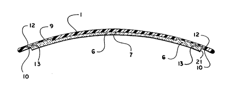
Figure 1 is a top view of a bridge plate without showing a cushion pad
beneath it;
Figure 2 is a side elevation view of a bridge plate and cushion pad
assembled;
Figure 3 is a bottom view of a bridge plate without a cushion pad in the
cushion receptacle;
~WO 941~2334 ~?lsg PCTIU594/03385
Figure 4 is an enlarged side view that has been cut away in part to show
portions of a cushion pad inside and outside of a cushion rece,utdGI~,
Figure 5 is a top view with a brassiere strap d~l,dched and cut away in part
~ to show a cushion pad from the top within the cushion receptacle;
Figure 6 is a bottom view of a bridge plate and a cushion pad assembled and
with a brdss;ere strap attached;
Figure 7 is a bottom view of an optional cushion pad that covers more of a
bottom of a bridge plate than the Figure 6 embodiment. A brassiere strap is
attached;
Figure 8 is a bottom view of a cushion pad of the type illu~l.l dt~d in Figure 6that is separate from the bridge plate;
Figure 9 is a side elevation view of the Figure 8 illus~-a~ioll;
Figure 10 is an enlarged sectional view of a cushion pad of the type shown
in Figure 6 that is partly separated from the bridge plate;
Figure 11 is a separate end elevation view of the cushion pad that is shown
in Figures 8-10;
Figure 12 is a separ-a~ bottom view of the cushion pad shown in Figure 7.
It has been cut away in part to show sections of the cushion pad which are
insertable into and which remain outside of a cushion receptacle;
Figure 13 is an enlarged sectional view of a cushion pad of the type shown
in Figure 7 that is partly separated from the bridge plate;
Figure 14 is an end view of the cushion pad shown in Figures 12 and 13;
WO 9412Z334 '''' ~ ~ i s 9 ~ 1 4 PCTIU594/03385
Figure 15 is a front view of the brassiere-shoulder-strap support attached
to a front portion of a brassiere and posi~ioned on a dashed~ine outline of a front
portion of a woman;
Figure 16 is a rear view of the brassiere-shoulder-strap support a~ched
to a rear portion of a brassiere and positioned on a dashed~ine outline of a rear
portion of a woman;
Figure 17 is a bottom view of another embod;.llel1t of a bridge plate without
showing the cushion pad beneath it;
Figure 18 is a top view of a cushion pad that fits the bridge plate shown in
Figure 17;
Figure 19 is a side elevation view of the cushion shown in Figure 18;
Figure 20 is a vertical section view taken along lines 2020 of Figure 17;
Figure 21 is a vertical section view taken along lines 2121 of Figure 17;
Figure 22 is a partial vertical section view taken along lines 2121 of
Figure 17 showing, however, the cushion pad of Figure 18 placed in the bottom ofthe bridge plate; and
Figure 23 is a partial vertical section view taken along lines 2020 of
Figure 17 showing, however, the cushion pad of Figure 18 placed in the bottom ofthe bridge plate.
2~1 Best Mode of Carrying Out the Invention.
Referring to the drawings wherein like ft:r~rel1ce nL" "erals designate
corresponding parts throughout the several figures, re~rence is made to Figure 1
~ ~ ~, t, $97~
showing a bridge plate 1 which is sized and shaped to form-fit the top of a woman s
shoulder under a brassiere strap. It is r ~rt~ ed to as a bridge plate 1 because it
distributes weight from a brassiere strap evenly over a broad portion of the
woman s shoulder in a uniform manner like a bridge. The bridge plate 1 is
constructed prer~rably from a light plastic n,dLerial that is sufficiently rigid to
distribute such weight evenly and yet not so rigid that it does not bend resiliently
in response to anticir~tsd movement of the woman s shoulder.
Shape of the bridge plate 1 is prr-r~rably elongate with a modified elliptical
form. Other elongate shapes also can be employed. Length of the bridge plate 1
is sufficient to extend from desired pruxi",iLy to the clavicle bone to desired
pru~imiLy to a top~ear portion of the woman s shoulder. The size and the length-to-
width proportions can vary consideral)ly for dirrerel1t women and for dirr~ rent use
conditions. Large medium and small sizes of the bridge plate are foreseeahle
Thickness of the bridge plate 1 also can be dirr~rent for difr~rent women and
for dirrtre~-t use conditions. Dirrt:rent sizes can be constructed with dirr~,ent
thicknesses.
At each opposite end of the bridge plate 1 is a brassiere-shoulder-strap-
aLLdc~""ent means 2. The brass;ele-shoulder-strap-dLLdchn1ent means 2 is
prert:rably a T-shaped strap bay co",,.3r;;,ed of a strap-e"tl-a"ce section 3 that is
parallel to an elongate axis of the bridge plate 1 and a strap-container section 4
that is perpendicular to the strap-entrance section 3. A brassiere strap is slid in
sideways through the strap-entrance section 3 and then turned parallel to the
strap-container section 4.
VenLildLion or-irices 5 can be provided in the bridge plate 1. The same
v~ntilaLion orifice 5 or separate orifices can be provided with dppropl-idL~ sizes for
- attaching r"dL~rial such as lace and fragrance packets.
Referring now to Figure 2 a cushion pad 6 can be removably attached to
a bottom side 7 of the generally concave bridge plate 1. This support for a
W0 94/22334 2 ¦S9~ 14 rcT/usg4/l)338s
brass;ere shoulder strap is con)pr;sed pr;"~rily of the bridge plate 1 and the
cushion plate 6. The bridge plate 1 distributes weight over a wide area and the
cushion pad 6 sur~ans contact between a woman's shoulder and the bridge plate 1.
Thickness of the cushion pad 6 depends to a great extent on its resil;e,1t
res;~ldnce to collapse or softness. Dirr~re,~t levels of softness are prt:r~" ed for
dirr~re"L women and for dirr~re~t use conditions.
Material for construction of the cushion pad 6 has several prer~rred
character;sLics or specirica~iuns. It can be washed easily without retaining adverse
odors or colors. It does not wear out soon from being washed and replaced often
in the same or dirr~re~t brasse,-;es. It has a resiliency which is surriciellt to bear
weight placed on the bridge plate 1 without col'~; sing to where the bridge plate 1
comes in contact with a woman's shoulder. The resiliency does not diminish with
repeated washing and wearing throughout its use life. It has relatively "non-skid"
contact with skin on a woman's shoulder to prevent it and a brassiere strap on it
from sliding off of a woman's shoulder.
Referring to Figures 2 and 3 the cushion pad 6 is removably placeable in
a cushion receptacle 8 in the concave bottom side 7 of the bridge plate 1. The
cushion receptacle 8 has a receptacle bottom 9 receptacle ends walls 10 and
receptacle side walls 11. The ventildtion orifices 5 extend into the cushion
receptacle 8. The brassiere-shoulder-strap-attachmenl means 2 are proxi~na~
receptacle end walls 10.
In Figure 4 there is shown at least two walls of the cushion recep~dcle
pr~rt:,dbly receptacle end walls 10 have retainer recesses 12. Pad dovetail
walls 13 are sized and shaped to fit agai~ I~L the retainer recesses 12 in dovetail-
i, ILt, lockil ,9 reldl ionship.
A brassiere shoulder strap 14 as seen in Figure 5 is placed on top of the
bridge plate 1 and positioned in the strap-container section 4 at each opposite end
of the bridge plate 1. In a cutaway section extending through a receptacle
~W0 94l2~334 ,,; S9~ PCT/[~S94/03385
bottom 9, cushion bottom 15 is rcveale~
Referring to Figure 6, a top 16 of the cushion pad 6 can be seen from a
bottom view. A brassiere shoulder strap 14 is extended down and out through the
~ strap-container sections 4 and onto a woman's shoulder.
It can been seen in Figure 7 that a fullbottom cushion pad 17 has overlap
end sections 18 and overlap side seLtiol1s 19. The overlap end sections 18 and
overlap side sections 19 extend beyond receptacle end walls 10 and receptacle
side walls 11 respectively. A bottom 20 of a fullbottom cushion pad 17 can be
made to cover an entire bottom side 7 [see Figures 2 and 4) of a bridge plate 1
except for portions immediately surrounding the strap-container sections 4.
Referring to Figures 8-11, a cushion pad 6 is shown separately in Figure 8
from the bottom, in Figure 9 from the side and in Figure 11 from an end. In
Figure 10, the pad dovetail wall 13 is shown separated from the retainer
recess 12. A cushion boss 21 is shown in Figures 10 and 11 as a portion of the
cushion pad 6 which extends beyond the bridge plate 1 in contact with a woman's
shoulder.
In Figures 12-14 the fullbottom cushion pad 17 is shown separately from
a cushion bottom 20 in Figure 12, separately from an end in Figure 14 and
separated from the retainer recess 12 in Figure 13. In Figure 12, an overiap endsection 18 and an overlap side section 19 are shown extending from a recept~cla
section 22 of the fullbotlul1l cushion pad 17. Between overlap end secLions 18
is strap-recess section 23 that is shown in Figures 12 and 14. In Figure 13, an
overlap end section 18 is shown in ~ hle conl~ct with a bottom side 7 of a
bridge plate 1 as pad dovetail walls 13 are brought in colltd~;l, with a retainer
recess 12 for attaching the cushion pad 17. For removing the fullbottom cushion
- pad 17 or the cushion pad 6, the pad dovetail walls 13 are removed from conL~
with the retainer recess 12 by graspi,lg either cushion pad 6 or 17 and pulling it
outwardly.
WO 94/22334 9~ ~4 PCT/US94/03385
~ 10
Either of the cushion pads 6 and 17 can be adhesively attached to the
cushion rece~.~cle 8 if desired. For adhesive a~L~ch,11ent chard.;~l ;~Iics of the
adhesive employed are cor"~udLible with chard-;l~r;~lics cf the cushion pads.
Preferably both are washable and odor~es; j~nt.
Referring to Figure 15 a brass;ere shoulder strap 14 is shown aLI dched to
a front portion of a brass;ere 24. The brassiere shoulder strap 14 is shown on the
bridge plate 1 resting on a shoulder 25 of a woman seen in part from a front view.
Referring to Figure 16 a brassiere shoulder strap 14 in a rear view of a
woman is shown attached to a rear portion of a brassiere 26. The brassiere
shoulder strap 14 is shown on the bridge plate 1 resting on the shoulder 25 of the
woman.
It can be seen from co",pc,r;.1g Figures 15 and 16 that there is a slight
dirrt:re,1ce in the distance of exL~ns,~", of the bridge plate 1 over the front of the
shoulder 25 in compdr;-~io" to the rear of the shoulder 25. This is optional anda~justahle. It also demons~ ates optional 1;3irr~rences in elongate lengths of bridge
plate 1 and cushion pads 6 or 16 that are removably placeable in it.
In another embod;,ment of the invention as shown in Fiyure 17 the bridge
plate 1 is shown in the same oval configuration with the brassiere- shoulder-strap-
attach"lent means 2 strap-entrance section 3 and strap-co~ er section 4 on
each end. Looking at the bottom of the bridge plate in Figure 17 the cushion
receptacle 8 holds the modified cushion 27 therein. The modified pad 27
co~ ;ae9 a two-part construction namely the hard preft:rably plastic backing
" IdLer;al 28 and a softer foam cushion pad 29. The " ~odi~ied pad 27 prer~rably has
therein a plurality of holes 33 matching the spacing of holes 5 of the bridge plate
to provide \ ~ntild~ion.
.
The bridge plate 1 of Figure 17 has retainer recesses 12 at each end of the
long direction of the plate and on the sides of the plate there are one or more
retainer gripping tabs 30 which project inwardly from the rim of the plate 31 along
-
~WO 94/7~334 ~S9~ PCTrUS94/03385
11
side walls 11. As more readily seen in the vertical cross-section in Figure 20, the
retainer tabs 30 form a retainer recess 32 between the tabs 30 and the cushion
receptacle area 8. The retainer recess 32 operates to engage the edge of the
back 28 of the cushion 27 within the retainer recess 32 so that the cushion pad
is not only held on the ends of the plate by means of the retainer recesses 12, but
is also snapped into firm engagement with the plate by means of the retainer
gripping tabs 30.
Thererure, as can be seen in Figure 22, at the ends of the bridge plate 1,
the cushion pad 27 is snapped into the retainer recesses 12 and the receptacle
end walls 10 hold the back 28 and engages the soft foam of the cushion pad 29
to m~ Ita;n firm engagement on the ends of the bridge plate. As can be seen in
Figure 23, the cushion pad 27 is ~-~ai"~ined in the bridge plate 1 by engage,l,ent
of the retainer tabs 30 with the back 28, and the tabs 30 also engage the cushion
pad 29. It can be seen that with this particular arrange",ent that there is little
chance, if any, that the cushion pad 27 will be .. ~ .ged by activities of the person
wearing the bridge plate. To mount the cushion pad 27 into the bridge plate, it is
merely necessary to place the cushion pad over the area 8 and then press upon
each end to snap the back 28 under retainer recesses 12, and then press the sideedges of the pad to snap the back 28 under retainer tabs 30.
It is conte,l,plated that all m~Lel-;als utilized in a bridge plate 1, and the
various cushion pads ~lisclosed herein, will be of medical grade ~"a~r;als and be
non-hypo-allergenic.
Various ~-,odirical,ions may be made of the invention without departing from
the scope thereof and it is desired, therefore, that only such linlitdtiol1s shall be
placed thereon as are imposed by the prior art and which are set forth in the
appended claims.