Some of the information on this Web page has been provided by external sources. The Government of Canada is not responsible for the accuracy, reliability or currency of the information supplied by external sources. Users wishing to rely upon this information should consult directly with the source of the information. Content provided by external sources is not subject to official languages, privacy and accessibility requirements.
Any discrepancies in the text and image of the Claims and Abstract are due to differing posting times. Text of the Claims and Abstract are posted:
| (12) Patent: | (11) CA 2159798 |
|---|---|
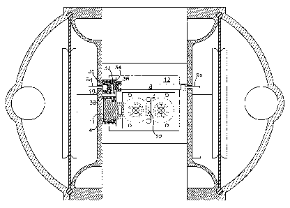
| (54) English Title: | MECHANICAL SHIFT, PNEUMATIC ASSIST PILOT VALVE |
| (54) French Title: | VANNE PILOTE A VANNE AUXILIAIRE PNEUMATIQUE |
| Status: | Term Expired - Post Grant Beyond Limit |
| (51) International Patent Classification (IPC): |
|
|---|---|
| (72) Inventors : |
|
| (73) Owners : |
|
| (71) Applicants : |
|
| (74) Agent: | NORTON ROSE FULBRIGHT CANADA LLP/S.E.N.C.R.L., S.R.L. |
| (74) Associate agent: | |
| (45) Issued: | 2004-12-07 |
| (22) Filed Date: | 1995-10-03 |
| (41) Open to Public Inspection: | 1996-04-12 |
| Examination requested: | 2002-10-01 |
| Availability of licence: | N/A |
| Dedicated to the Public: | N/A |
| (25) Language of filing: | English |
| Patent Cooperation Treaty (PCT): | No |
|---|
| (30) Application Priority Data: | ||||||
|---|---|---|---|---|---|---|
|
A pneumatic assist valve receives constant air pressure from supply air to provide the pneumatic assist to shift the pilot, eliminating false signals acting on the trip rod and the design also assures the pilot has completely shifted before diaphragm reversal occurs.
Une valve auxiliaire pneumatique reçoit une pression d'air fourni constante afin de fournir un soutien pneumatique permettant de déplacer la valve pilote, éliminant ainsi les faux signaux agissant sur la tige de déclenchement. De plus, la conception permet de garantir que la valve pilote a été complètement déplacée avant le renversement du diaphragme.
Note: Claims are shown in the official language in which they were submitted.
Note: Descriptions are shown in the official language in which they were submitted.
2024-08-01:As part of the Next Generation Patents (NGP) transition, the Canadian Patents Database (CPD) now contains a more detailed Event History, which replicates the Event Log of our new back-office solution.
Please note that "Inactive:" events refers to events no longer in use in our new back-office solution.
For a clearer understanding of the status of the application/patent presented on this page, the site Disclaimer , as well as the definitions for Patent , Event History , Maintenance Fee and Payment History should be consulted.
| Description | Date |
|---|---|
| Inactive: Expired (new Act pat) | 2015-10-03 |
| Inactive: Late MF processed | 2009-10-20 |
| Letter Sent | 2009-10-05 |
| Inactive: IPC from MCD | 2006-03-12 |
| Inactive: IPC from MCD | 2006-03-12 |
| Grant by Issuance | 2004-12-07 |
| Inactive: Cover page published | 2004-12-06 |
| Inactive: Final fee received | 2004-09-14 |
| Pre-grant | 2004-09-14 |
| Letter Sent | 2004-07-30 |
| Notice of Allowance is Issued | 2004-07-30 |
| Notice of Allowance is Issued | 2004-07-30 |
| Inactive: Approved for allowance (AFA) | 2004-07-12 |
| Inactive: Application prosecuted on TS as of Log entry date | 2002-11-07 |
| Letter Sent | 2002-11-07 |
| Inactive: Status info is complete as of Log entry date | 2002-11-07 |
| All Requirements for Examination Determined Compliant | 2002-10-01 |
| Request for Examination Requirements Determined Compliant | 2002-10-01 |
| Amendment Received - Voluntary Amendment | 2002-10-01 |
| Application Published (Open to Public Inspection) | 1996-04-12 |
There is no abandonment history.
The last payment was received on 2004-09-21
Note : If the full payment has not been received on or before the date indicated, a further fee may be required which may be one of the following
Patent fees are adjusted on the 1st of January every year. The amounts above are the current amounts if received by December 31 of the current year.
Please refer to the CIPO
Patent Fees
web page to see all current fee amounts.
Note: Records showing the ownership history in alphabetical order.
| Current Owners on Record |
|---|
| THE ARO CORPORATION |
| INGERSOLL-RAND COMPANY |
| Past Owners on Record |
|---|
| NICHOLAS, JR. KOZUMPLIK |
| RICHARD K. GARDNER |

