Sélection de la langue

Search

Sommaire du brevet 2159798 

Énoncé de désistement de responsabilité concernant l'information provenant de tiers

Une partie des informations de ce site Web a été fournie par des sources externes. Le gouvernement du Canada n'assume aucune responsabilité concernant la précision, l'actualité ou la fiabilité des informations fournies par les sources externes. Les utilisateurs qui désirent employer cette information devraient consulter directement la source des informations. Le contenu fourni par les sources externes n'est pas assujetti aux exigences sur les langues officielles, la protection des renseignements personnels et l'accessibilité.

Disponibilité de l'Abrégé et des Revendications

L'apparition de différences dans le texte et l'image des Revendications et de l'Abrégé dépend du moment auquel le document est publié. Les textes des Revendications et de l'Abrégé sont affichés :

  • lorsque la demande peut être examinée par le public;
  • lorsque le brevet est émis (délivrance).
(12) Brevet: (11) CA 2159798
(54) Titre français: VANNE PILOTE A VANNE AUXILIAIRE PNEUMATIQUE
(54) Titre anglais: MECHANICAL SHIFT, PNEUMATIC ASSIST PILOT VALVE
Statut: Durée expirée - au-delà du délai suivant l'octroi
Données bibliographiques
(51) Classification internationale des brevets (CIB):
  • F16K 11/00 (2006.01)
  • F01L 25/06 (2006.01)
  • F04B 43/073 (2006.01)
(72) Inventeurs :
  • KOZUMPLIK, NICHOLAS, JR. (Etats-Unis d'Amérique)
  • GARDNER, RICHARD K. (Etats-Unis d'Amérique)
(73) Titulaires :
  • THE ARO CORPORATION
  • INGERSOLL-RAND COMPANY
(71) Demandeurs :
  • THE ARO CORPORATION (Etats-Unis d'Amérique)
  • INGERSOLL-RAND COMPANY (Etats-Unis d'Amérique)
(74) Agent: NORTON ROSE FULBRIGHT CANADA LLP/S.E.N.C.R.L., S.R.L.
(74) Co-agent:
(45) Délivré: 2004-12-07
(22) Date de dépôt: 1995-10-03
(41) Mise à la disponibilité du public: 1996-04-12
Requête d'examen: 2002-10-01
Licence disponible: S.O.
Cédé au domaine public: S.O.
(25) Langue des documents déposés: Anglais

Traité de coopération en matière de brevets (PCT): Non

(30) Données de priorité de la demande:
Numéro de la demande Pays / territoire Date
08/320,811 (Etats-Unis d'Amérique) 1994-10-11

Abrégés

Abrégé français

Une valve auxiliaire pneumatique reçoit une pression d'air fourni constante afin de fournir un soutien pneumatique permettant de déplacer la valve pilote, éliminant ainsi les faux signaux agissant sur la tige de déclenchement. De plus, la conception permet de garantir que la valve pilote a été complètement déplacée avant le renversement du diaphragme.


Abrégé anglais

A pneumatic assist valve receives constant air pressure from supply air to provide the pneumatic assist to shift the pilot, eliminating false signals acting on the trip rod and the design also assures the pilot has completely shifted before diaphragm reversal occurs.

Revendications

Note : Les revendications sont présentées dans la langue officielle dans laquelle elles ont été soumises.


What is claimed is:
1. A mechanical shift pneumatic assisted pilot valve
for a reciprocating function comprising:
a reciprocating piston disposed in a bore intermediate
a first and a second reciprocating element and being
provided with a means at one end for directly contacting
paid first reciprocating element in one operating position
end a pneumatic piston at another end, said pneumatic piston
being further provided with a means for contacting said
second reciprocating element in a second operating position;
and
said pneumatic piston being a stepped piston having a
lesser diameter constantly pressurized in one biasing
direction and a greater diameter alternately pressurized in
an opposite biasing direction in response to mechanical
shift of said pneumatic piston effected by said means for
contacting said second reciprocating element said mechanical
shift further effecting reversal of direction of said first
and second reciprocating elements.
2. A mechanical shift pneumatic assisted pilot valve
for a reciprocating function according to claim 1 wherein:
said first and second reciprocating elements further
comprise pumping elements.
9

3. A mechanical shift pneumatic assisted pilot valve
for a reciprocating function according to claim 1 wherein:
said pumping elements comprise pump diaphragms.
4. A mechanical shift pneumatic assisted pilot valve
for a reciprocating function according to claim 1 wherein:
said means at one end for directly contacting said first
reciprocating element in one operating position comprises a
contact pin of minimum structural diameter projecting into a
pressurized operating cavity of a pumping element so as to
minimize the cavity pressure effect on said contact pin and
said reciprocating piston.
5. A mechanical shift pneumatic assisted pilot valve
for a reciprocating function according to claim 1 wherein:
said means for directly contacting said second reciprocating
element in a second operating position comprises a second
contact pin of minimum structural diameter projecting into a
pressurized operating cavity of a pumping element thereby
minimizing the cavity pressure effect on said second contact
pin and said pneumatic piston.
6. A mechanical shift pneumatic assisted pilot valve
for a reciprocating function according to claim 1 wherein:
said pneumatic piston further comprises a stepped piston
10

having a greater diameter face alternately exposed to
pressure fluid to effect longitudinal translation of said
pneumatic piston in response to said pneumatic piston being
displaced by said second contact pin in a longitudinal
direction.
7. A mechanical shift pneumatic assisted pilot valve
for a reciprocating function according to claim 6 wherein:
said pneumatic piston is disposed in a stepped bore having a
major diameter and a minor diameter corresponding to and co-
operating with a major diameter and a minor diameter of said
pneumatic piston.
8. A mechanical shift pneumatic assisted pilot valve
for a reciprocating function according to claim 7 wherein:
said stepped bore is sealed at its said major diameter end,
open to a constant source of pressure fluid at its minor
diameter end, and vented intermediate its major and minor
ends.
9. A mechanical shift pneumatic assisted pilot valve
for a reciprocating function according to claim 8 wherein:
said pneumatic piston is further provided with means for
alternately effecting flow of pressure fluid from said
constant source of pressure fluid to said major diameter end
11

and to vent in response to mechanical shift of said
pneumatic piston.
10. A mechanical shift pneumatic assisted pilot valve
for a reciprocating function according to claim 9 wherein:
said means for alternately effecting flow of pressure fluid
from said constant source of pressure fluid to said major
diameter end and to vent in response to mechanical shift of
said pneumatic piston further comprises a valve on said
pneumatic piston minor diameter and a passage
interconnecting said valve and said major end of said
pneumatic piston.
12

Description

Note : Les descriptions sont présentées dans la langue officielle dans laquelle elles ont été soumises.

21 ~ 9 7 ~ 8 Docket No . 2 3 2 8-AR-FH
IMPROVED MECHANICAL SHIFT, PNEUMATIC ASSIST PILOT VALVE
BACKGROUND OF THE INVENTION
This invention relates generally to mechanical shift,
pneumatic assist valves and more particularly to a
mechanical shift pneumatic assist valve for diaphragm pumps
which use a separate pilot valve to provide a positive
signal (either on or off to the major air distribution
valve).
Disclosed is an improvement of the device described in
Patent No. 4,854,832 assigned to The Aro Corporation. The
prior art device significantly reduced the possibility of
motor stall by providing a positive signal (either on or
off) to the major air distribution valve. This was
accomplished by adding a separate valve (pilot) which was
not connected to the diaphragm rod. Actuation of the valve
was accomplished by mechanically pushing the valve to the
trip point with the diaphragm washer attached to the
diaphragm connecting rod causing the major valve to shift.
As pressure built up in the diaphragm air chamber it also
acts on the end of the pilot rod (area) and forced it to end
of its stroke. Air pressure holds it in this position until
the diaphragm washer pushes it in the opposite direction.
As long as the pilot rod was in either extreme position, a
signal is always present to the major valve.
~1

Docket No. 2328-AR~FH
Other designs which incorporate the 'pilot' on the
diaphragm connecting rod, shut the signal off to the major
valve after the diaphragm changes direction.
Occasionally an air pressure spike occurs in the
diaphragm air chamber which is being exhausted. The spike
occurs when there is an unusually rapid reversal of the
diaphragms due to malfunctioning check valves or large
volume of air trapped in one or both air caps or a
restriction in the exhaust. If this pressure spike exceeds
the pressure of the incoming air of the chamber being
pressurized to pneumatically assist the trip rod, the spike
can cause the trip rod to back up. Depending on the pump
speed, operating pressure and severity of any one of the
above conditions, the pump may begin to rapidly short stroke
because the trip rod is oscillating back and forth around
the trip point and out of sync with the diaphragm rod.
Occasionally this condition results in a motor stall.
The foregoing illustrates limitations known to exist
in present devices and methods. Thus, it is apparent that
it would be advantageous to provide an alternative directed
to overcoming one or more of the limitations set forth
above. Accordingly, a suitable alternative is provided
including features more fully disclosed hereinafter.
2

215 9 7 9 $ Docket No . 2 3 2 8 -AR-FH
SUMMARY OF THE INVENTION
In one aspect of the present invention this is
accomplished by providing a mechanical shift pneumatic
assisted pilot valve for a reciprocating function comprising
a reciprocating piston disposed in a bore intermediate a
first and a second reciprocating element and being provided
with a means at one end for directly contacting the first
reciprocating element in one operating position and a
pneumatic piston at another end, the pneumatic piston being
further provided with a means for contacting the second
reciprocating element in a second operating position: and
the pneumatic piston being a stepped piston having a lesser
diameter constantly pressurized in one biasing direction and.
a greater diameter alternately pressurized in an opposite
biasing direction in response to mechanical shift of the
pneumatic piston effected by the means for contacting the
second reciprocating element the mechanical shift further
effecting reversal of direction of the first and second
reciprocating elements.
The foregoing and other aspects will become apparent
from the following detailed description of the invention
when considered in conjunction with the accompanying drawing
figures.
~3

Docket No. 2328-AR-FH
BRIEF DESCRIPTION OF THE DRAWING FIGURES
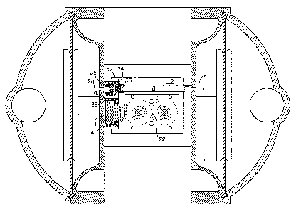
Fig. 1 is a cross section of a diaphragm pump showing
an air motor major valve according to the present invention;
Fig. 2 is a cross section of an improved mechanical
shift, pneumatic assist pilot valve according to the present
invention showing the pilot valve:
Fig. 3 is a cross section detail showing the pilot
valve according to the present invention in the extreme left
position:
Fig. 4 is a cross section detail showing the air motor
major valve spool in the extreme left hand position;
Fig. 5 is a cross section detail showing the pilot
valve in the extreme right hand position; and
Fig. 6 is a cross section detail showing the major
valve in the extreme right hand position.
DETAILED DESCRIPTION
Fig. 1 is a cross sectional view of the air motor
major valve. Fig. 2 is a view of the pilot valve. Both
valves are shown in dead center position.
4

_~15979~
Docket No. 2328-AR-FH
In Fig. 1 the major valve consists of a spool 1, valve
block 2, valve plate 3, power piston 4, quick dump valves 5a
and 5b and housing 6. Fig. 2 shows the pilot valve
according to the present invention consisting of pilot
piston 7, pushrod 8 and actuator pins 9a and 9b. Both
valves are located in the same cavity 12 which is
pressurized with supply air. The power piston 4 and pilot
piston 7 are differential pistons. Air pressure acting on
the small diameters of the pistons will force the pistons to
the left when pilot signal is not present in chambers 10
and 11. The area ratio from the large diameter to the small
diameter is approximately 2:1. When the pilot signal is
present in chambers 10 and 11 the pistons are forced to the
right as shown in Figs. 5 and 6.
In Fig. 4 the spool 1 of the main valve is shown in
its extreme left position as is pilot piston 7 in Fig. 3.
Air in cavity 12 flows through orifice 13 created between
spool 1 and valve block 2 through port 14 in valve plate 3.
The air impinging on the upper surface of check 5a forces it
to seat and seal off exhaust port 15. The air flow deforms
the lips of the elastomeric check as shown in Fig. 4. Air
flows around the check into port 17 and into diaphragm
chamber 18. Air pressure acting on the diaphragm 19 forces
it to the right expelling fluid from the fluid chamber 20
through an outlet check valve 50 (see Fig. 1).
5

Docket No. 2328-AR-FH
Operation of the fluid check valves control movement
of fluid in and out of the fluid chambers causing them to
function as single acting pumps. By connecting the two
chambers through external manifolds 51 output flow from the
pump becomes relatively constant.
At the same time chamber 18 is filling, the air above
check 5b has been exhausted through orifice 21, port 22 and
into exhaust cavity 23. This action causes a pressure
differential to occur between chambers 24 and 25. The lips
of valve 5b relax against the wall of chamber 25. As air
begins to flow from air chamber 26 through port 27, it '
forces check 5b to move upward and seats against valve plate
3 and seal off port 28 and opens port 16. Exhaust air is
dumped into cavity 23.
Diaphragm 19 is connected to diaphragm 29 through
shaft 30 which causes them to reciprocate together. As
diaphragm 19 traverses to the right diaphragm 29 evacuates
fluid chamber 31 which causes fluid to flow into fluid
chamber 31 through an inlet check 55. As the diaphragm
assembly approaches the end of the stroke, diaphragm washer
33 pushes actuator pin 9a to the right. The pin in turn
pushes pilot piston 7 to the right to the position shown in
Fig. 5. 0-ring 35 is engaged in bore of sleeve 34 and
6

- ~ ~ ~ ~ Docket No . 2 3 2 8 -AR-FH
O-ring 36 exits the bore to allow air to flow from air
cavity 12 through port 37 in pilot piston 7 and into cavity
10. Air pressure acting on the large diameter of pilot
piston 7 causes the piston to shift to the right.
The air that flows into chamber 10 also flows into
chamber 11 through passage 38 which connects the two bores.
When the pressure reaches approximately 50% of supply
pressure, the power piston 4 shifts spool 1 to the position
shown in Fig. 6. Air being supplied to chamber 18 is shut
off and chamber 38 is exhausted through orifice 41. This
causes check 5a to shift connecting air chamber 18 to
exhaust port 15. At the same time air chamber 26 is
connected to supply air through orifice 40 and port 28 and
27. The air pressure acting on diaphragm 29 causes the
diaphragms to reverse direction expelling fluid from fluid
chamber 31 through the outlet check 56 while diaphragm 19
evacuates fluid chamber 20 to draw fluid into fluid chamber
20.
As diaphragm 19 approaches the end of its stroke,
diaphragm washer 39 pushes actuator pin 9b. The motion is
transmitted through pushrod 8 to pilot piston 7 moving it to
the trip point shown in Fig. 2. O-ring 36 reenters the bore
in sleeve 34 and seals off the air supply to chambers l0 and
_7

2~~9~~~
- Docket No. 2328-AR-FH
11. O-ring 35 exits the bore to connect chambers 10 and 11
to port 37 in pilot piston 7. The air from the two chambers
flows through port 42 into exhaust cavity 23. Air in air
cavity 12 acting on the small diameters of pistons 4 and 7
forces both to the left as shown in Fig. 3. The power
piston 4 will pull spool 1 to the left to begin a new cycle
as shown in Fig. 4.
Having described our invention in terms of a preferred
embodiment, we do not wish to be limited in the scope of our
invention except as claimed.
8

Dessin représentatif
Une figure unique qui représente un dessin illustrant l'invention.
États administratifs

2024-08-01 : Dans le cadre de la transition vers les Brevets de nouvelle génération (BNG), la base de données sur les brevets canadiens (BDBC) contient désormais un Historique d'événement plus détaillé, qui reproduit le Journal des événements de notre nouvelle solution interne.

Veuillez noter que les événements débutant par « Inactive : » se réfèrent à des événements qui ne sont plus utilisés dans notre nouvelle solution interne.

Pour une meilleure compréhension de l'état de la demande ou brevet qui figure sur cette page, la rubrique Mise en garde , et les descriptions de Brevet , Historique d'événement , Taxes périodiques et Historique des paiements devraient être consultées.

Historique d'événement

Description Date
Inactive : Périmé (brevet - nouvelle loi) 2015-10-03
Inactive : TME en retard traitée 2009-10-20
Lettre envoyée 2009-10-05
Inactive : CIB de MCD 2006-03-12
Accordé par délivrance 2004-12-07
Inactive : Page couverture publiée 2004-12-06
Inactive : Taxe finale reçue 2004-09-14
Préoctroi 2004-09-14
Lettre envoyée 2004-07-30
Un avis d'acceptation est envoyé 2004-07-30
Inactive : Approuvée aux fins d'acceptation (AFA) 2004-07-12
Inactive : Dem. traitée sur TS dès date d'ent. journal 2002-11-07
Lettre envoyée 2002-11-07
Inactive : Renseign. sur l'état - Complets dès date d'ent. journ. 2002-11-07
Toutes les exigences pour l'examen - jugée conforme 2002-10-01
Exigences pour une requête d'examen - jugée conforme 2002-10-01
Modification reçue - modification volontaire 2002-10-01
Demande publiée (accessible au public) 1996-04-12

Historique d'abandonnement

Il n'y a pas d'historique d'abandonnement

Taxes périodiques

Le dernier paiement a été reçu le 2004-09-21

Avis : Si le paiement en totalité n'a pas été reçu au plus tard à la date indiquée, une taxe supplémentaire peut être imposée, soit une des taxes suivantes :

  • taxe de rétablissement ;
  • taxe pour paiement en souffrance ; ou
  • taxe additionnelle pour le renversement d'une péremption réputée.

Les taxes sur les brevets sont ajustées au 1er janvier de chaque année. Les montants ci-dessus sont les montants actuels s'ils sont reçus au plus tard le 31 décembre de l'année en cours.
Veuillez vous référer à la page web des taxes sur les brevets de l'OPIC pour voir tous les montants actuels des taxes.

Titulaires au dossier

Les titulaires actuels et antérieures au dossier sont affichés en ordre alphabétique.

Titulaires actuels au dossier
THE ARO CORPORATION
INGERSOLL-RAND COMPANY
Titulaires antérieures au dossier
NICHOLAS, JR. KOZUMPLIK
RICHARD K. GARDNER
Les propriétaires antérieurs qui ne figurent pas dans la liste des « Propriétaires au dossier » apparaîtront dans d'autres documents au dossier.
Documents

Pour visionner les fichiers sélectionnés, entrer le code reCAPTCHA :


Pour visualiser une image, cliquer sur un lien dans la colonne description du document (Temporairement non-disponible). Pour télécharger l'image (les images), cliquer l'une ou plusieurs cases à cocher dans la première colonne et ensuite cliquer sur le bouton "Télécharger sélection en format PDF (archive Zip)" ou le bouton "Télécharger sélection (en un fichier PDF fusionné)".

Liste des documents de brevet publiés et non publiés sur la BDBC .

Si vous avez des difficultés à accéder au contenu, veuillez communiquer avec le Centre de services à la clientèle au 1-866-997-1936, ou envoyer un courriel au Centre de service à la clientèle de l'OPIC.

({010=Tous les documents, 020=Au moment du dépôt, 030=Au moment de la mise à la disponibilité du public, 040=À la délivrance, 050=Examen, 060=Correspondance reçue, 070=Divers, 080=Correspondance envoyée, 090=Paiement})


Description du
Document 
Date
(aaaa-mm-jj) 
Nombre de pages   Taille de l'image (Ko) 
Dessin représentatif 1999-06-24 1 33
Description 1995-10-02 8 255
Abrégé 1995-10-02 1 10
Revendications 1995-10-02 4 119
Dessins 1995-10-02 4 170
Dessin représentatif 2004-04-12 1 23
Rappel de taxe de maintien due 1997-06-02 1 109
Rappel - requête d'examen 2002-06-03 1 118
Accusé de réception de la requête d'examen 2002-11-06 1 176
Avis du commissaire - Demande jugée acceptable 2004-07-29 1 162
Avis concernant la taxe de maintien 2009-11-04 1 170
Quittance d'un paiement en retard 2009-11-04 1 163
Correspondance 2004-09-13 1 28