Note: Descriptions are shown in the official language in which they were submitted.
~ WO941~162 21~ ~ 2 ~ PCT~S94/03668
1 --
IMPROVED COLLAPSIBLE SHELTER WITH ELEVATED CANOPY
BACKGROUND OF THE INVENTION
Field of the Invention:
This invention relates generally to folding,
collapsible structures, and more particularly relates to a
collapsible, field shelter structure having an elevated canopy.
Descri~tion of Related Art:
Temporary shelters that can be easily transported and
rapidly set up at emergency sites can be particularly useful in
providing temporary care and housing. Such shelters can also be
useful for non-emergency outdoor gatherings, such as for
temporary military posts, field trips, and the like. One such
quickly erectable, collapsible shelter having a framework of X-
shaped linkages, telescoping legs, and a canopy covering the
framework is described in my U.S. Patent No. 4,607,656. The legs
of that shelter are capable of telescoping to about twice their
stowed length, and the framework of X-shaped truss pairs is
capable of horizontal extension between the legs to support a
canopy. The framework can be constructed of lightweight
material, and the telescoping legs can be extended to raise the
framework of the shelter. However, the height of the canopy is
limited to the extended length of the legs, and the canopy is
essentially flat, allowing for collection of precipitation and
debris on top of the canopy, which can promote leaks and tears in
the canopy. In addition, the size and stability of the shelter
is generally limited by the strength of the framework.
It would be desirable to provide an improved
collapsible shelter with a support framework for the canopy that
rises above the supporting legs, to provide for more headroom
within the structure, and to allow for a reduction in the size
and weight of the legs and framework required to achieve an
adequate height of the canopy. It would also be desirable to
provide a canopy structure that is gabled to shed precipitation
and debris from the top of the shelter. It would be further
desirable to provide a shelter framework that would provide
greater strength and stability, to allow support of larger,
WO94/~162 215 ~82~ PCT~S94/03668 ~
-- 2
lighter collapsible shelter structures. The present invention
fulfills these needs.
SUMMARY OF THE INVENTION
Briefly, and in genera~ terms, the present invention
provides for a collapsible shelter with an improved truss
framework that raises a gabled shelter canopy to provide
increased headroom, strength and stability.
The invention accordingly provides for a collapsible
shelter having a canopy with at least three vertically disposed
legs supporting the canopy. At least one perimeter truss means
is connected to each of the legs. Each of the perimeter truss
means preferably includes a pair of first and second link
members, with the first link member having an outer end connected
to the upper end of one leg, and the second link member having an
outer end slidably connected to the leg. The first and second
link members are pivotally connected together in a scissors
configuration so as to be extendable from a first collapsed
position exten~;ng horizontally between two legs to a second
extended position extending above the legs. In a preferred
embodiment, the perimiter truss means includes a second perimeter
truss pair of link members connected to each of the first
perimeter truss pairs, with the first link of the second
perimeter truss pairs being pivotally connected to the second
link of a corresponding first perimeter truss pair, and the
second link of the second perimeter truss pair being pivotally
connected to the first link of the corresponding first perimeter
truss pair. The first and second link members of the second
perimeter truss pairs are also preferably pivotally connected
together in a modified scissors configuration so as to be
exten~hle from a first collapsed position extending horizontally
between legs to a second extended position extending above the
~irst perimeter truss pair.
At least two central truss means are also provided,
with each of the central truss means including a pair of first
and second link members connected together in a scissors
configuration. Each of the central truss pairs are connected to
~ WO94/~162 2 I S ~ 8 2 ~ PCT~S94/03668
3 --
the inner ends of one perimeter truss means, and the first and
second link members are pivotally connected together in a
scissors configuration so as to be extendable from a first
collapsed position to a second extended position. In a preferred
embodiment, tensioning means are also secured between the leg
slider member and the central support slider member, to provide
additional strength and stability to the framework of the shelter
in a raised, extended configuration.
I In a preferred four-sided shelter embodiment, two first
perimeter truss pairs of link members are connected to each of
four legs. For each leg, the outer end of the first link of each
truss pair connected to the leg is pivotally connected to the
upper end of a leg, and the outer end of the second link is
slidably connected to the leg, preferably being pivotally secured
lS to a slider member on the leg. The first and second link members
are pivotally connected together in a modified scissors
configuration so as to be ext~n~Ahle from a first collapsed
position exten~;ng horizontally between adjacent legs to a second
extended position extending above the legs. Second perimeter
truss pairs of link members are also preferably connected to each
of the first perimeter truss pairs, with the first link of the
second perimeter truss pairs being pivotally connected to the
second link of a corresponding first perimeter truss pair, and
the second link of the the second perimeter truss pair being
pivotally connected to the first link of the corresponding first
perimeter truss pair. The first and second link members of the
second perimeter truss pairs are also preferably pivotally
connected together in a modified scissors configuration so as to
be ext~n~Ahle from a first collapsed position ext~n~;ng
horizontally between legs to a second extended position extending
above the first perimeter truss pair. Each of the second
perimeter truss pairs are preferably pivotally connected to
another second perimeter truss pair.
At least two first central truss pairs of link members
are also provided in the four-sided shelter embodiment, pivotally
connected together in a scissors configuration are each connected
to the inner ends of one of the perimeter truss pairs, and are
preferably pivotally connected to a junction of the inner ends of
WO94/~16~ 21~8~5 PCT~594/03668
second perimeter truss pairs. At least two second, inner central
truss pairs of link members pivotally connected together in a
scissors configuration are preferably each pivotally connected to
the inner ends of one of the first, outer central truss pairs.
The inner ends of the central ~russ pairs are preferably
pivotally connected to the inner ends of at least one other of
the inner central truss pairs, and are preferably pivotally
connected to a vertically oriented central support member
supporting the canopy and a central support slider member
disposed to slidably engage the central support member.
Tensioning means are also preferably provided between the leg
slider member and the central support slider member.
These and other aspects and advantages of the invention
will become apparent from the following detailed description, and
the acco~rAnying drawing, which illustrates by way of example the
features of the invention.
BRIEF DESCRIPTION OF THE ~RAWINGS
Fig. l is a perspective view of the improved
collapsible shelter with an elevated canopy of the invention,
showing the elevated gabled roof structure;
Fig. 2 is a cross-sectional elevational view of the
collapsible shelter of the invention, taken along line 2-2 of
Fig. l, showing the perimeter and central truss pairs of the
shel~er in an extended, raised configuration;
Fig. 3 is a top sectional view of the collapsible
shelter of the invention;
Fig. 4 is an enlarged view of a portion of the linkage
between the perimeter truss pairs and the central truss pairs;
Fig. 5 is an enlarged sectional view of a leg of the
collapsible shelter, taken along line 5-5 of Fig. 3;
Fig. 6 is a side elevational view of the framework of
the collapsible shelter, showing the perimeter truss pairs in a
substantially collapsed configuration: and
Fig. 7 is a top sectional view of a three-sided
embodiment of the collapsible shelter of the invention, similar
to that shown in Fig. 3.
~ WO94/D162 21 ~ 9 8 2 ~ PCT~S94/03668
5 --
DETAILED DESCRIPTION OF A PREFERRED EMBODIMENT
The size and available headroom of previous collapsible
shelters have been generally limited by the extended length of
the legs of the structure, and provided essentially flat roof
structures, allowing for collection of precipitation in pockets
or puddles on top of the shelter. The improved collapsible
shelter of the invention provides for larger, lighter collapsible
shelter structures, with a raised gabled roof structure which
also improves the strength and stability of the shelter.
As is illustrated in the drawings, and particularly
referring to the four-sided preferred embodiment shown in Fig. 1,
the invention is embodied in an improved collapsible shelter lO,
having a canopy 12 with at least three sides 14, and preferably
four sides, at least three corners 16, and preferably four
corners. The canopy is preferably formed of nylon fabric, so as
to be light and easily transportable, although the canopy could
also be made of other suitable sheet materials, such as canvass,
or other types of cloth fabric, or plastic. At least three, and
preferably four, legs 18 supporting the canopy, with a leg
disposed under each corner of the canopy. Particularly referring
to Figs. 2 and 5, each of the legs has an upper end 20 and a
lower end 22, and preferably each leg includes telescoping upper
and lower sections 24 and 26, respectively, with the telescoping
lower section including a spring loaded detent pin 27 for
indexing in apertures 28 provided in the upper section for
adjusting the leg height as desired. The ext~n~Ahle lower
section also preferably includes a foot portion 29 for engagement
with the ground or other floor surface.
As is best seen in Fig. 2, a leg slider member 32 is
also slidably mounted on the upper section of each of the legs.
A spring loaded detent pin 34 is also provided in the upper leg
section for indexing with an aperture 36 in the leg slider
member, as will be further explained below.
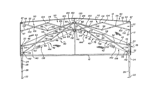
Referring to Figs. 2 and 6, in the preferred four sided
embodiment, the perimeter framework 38 includes perimeter truss
means 40 including two first perimeter truss pairs 42 of link
members connected to each of the legs at right angles, with each
W094/~16~ 2 ~ 9 82~ - 6 - PCT~594103668
of the first perimeter truss pairs including a first link member
44 having an outer end 46 connected to the upper end of a leg, an
inner end 48, a longitudinal center 50, and a pivot point 52
spaced apart from the longitudinal center toward the outer end by
a predetermined distance L~. Each of the first perimeter truss
pairs further includes a second link 54 having an outer end 56
pivotally connected to the leg slider member, thus slidably
connecting the second link ~o the upper section of the leg. The
second link of the first perimeter truss pairs includes an inner
end 58, a longitudinal center 60, and a pivot point 62 spaced
apart from the longitudinal center toward the inner end by the
same predetermined distance L1. The pivot points of the first
and second links in each of the first perimeter truss pairs are
pivotally connected in a modified scissors configuration, so that
although the first and second link members extend a short
distance generally horizontally toward another leg in a first
collapsed position of the shelter, as shown in Fig. 6, the first
and second link members extend to a second extended position with
the inner ends of the link members extending above the upper end
of the leg, as shown in Fig. 2.
In a preferred embodiment, the perimeter truss means
also includes a second perimeter truss pair 64 of link members,
which is pivotally connected to each of the first perimeter truss
pairs, to extend the framework further above the legs of the
shelter. Each of the second perimeter truss pairs preferably
includes a first link 66 having an outer end 68 pivotally
connected to the inner end of the second link of the associated
first perimeter truss pair, an inner end 70, a longit1l~inAl
center point 72, and a pivot point 74 spaced apart from the
longitudinal center point toward the inner end a predetermined
distance ~ Each of the second perimeter truss pairs also
preferably includes a second link 76 having an outer end 78
pivotally connected to the inner end of the first link of the
associated first perimeter truss pair, an inner end 80, a
longitudinal center point 82, and a pivot point 84 spaced apart
from the longitudinal center point toward the outer end the
predetermined distance ~. The pivot points of the first and
second links in each of the second perimeter truss pairs are
~ wo 94~162 2 1 5 9 8 2 a PCT~S94/03668
preferably pivotally connected together, resulting in a modified
scissors configuration so that the second truss pairs are also
extendable from a first collapsed position extending generally
horizontally between legs, to a second extended position
extending above the first perimeter truss pair. The inner ends
70 and 80 of each second perimeter truss pair are further
preferably pivotally connected to the inner ends 70 and 80 of
another second perimeter truss pair at a junction 86 centered
between two legs of one side of the shelter framework.
As is best seen in Figs. 2, 3 and 4, a plurality of
central truss means 88 are also provided, including at least two
outer central truss pairs 90 of link members, with each of the
outer central truss pairs being pivotally connected to the inner
ends of at least one of the second perimeter truss pairs at the
junction 86, such as by right angle bracket members 87, to which
the inner ends of the second perimeter truss pairs and the outer
central truss pairs are pivotally connected. In a preferred
embodiment, the framework of the shelter has a square
configuration, and four outer central truss pairs are provided,
connected to the four side junctions of the shelter framework.
Where the shelter framework has three sides, three outer central
truss pairs may be provided. Each of the outer central truss
pairs preferably includes a first link 92 having an outer end 94
connected to the inner end of the second link of the second
perimeter truss pair, an inner end 96, and a pivot point 98
located at the longitudinal center point of the outer central
truss pair first link. Each of the outer central truss pairs
also preferably includes a second link lO0 having an outer end
102 connected to the inner end of the first link of the second
perimeter truss pair, an inner end 104, and a pivot point 106
located at the longitudinal center point of the outer central
truss pair second link. Each of the pivot points of the first
and second links of the outer central truss pairs are pivotally
connected together to extend horizontally between the sides of
the shelter framework.
In a preferred embodiment, the central truss means also
includes at least two inner central truss pairs 110 of link
members, with each of the inner central truss pairs being
W094/~162 2 ~ 5 9 8 2 ~ PCT~S94/03668 ~
-- 8
pivotally connected to the inner ends of an associated outer
center truss pair. Each of the inner central truss pairs
preferably includes a first link 112 having an outer end 114
connected to the inner end of the second link of the outer
central truss pair, an inner end 116, and a pivot point 118
located at the longitudinal center pbint of the inner central
truss pair first link. Each of the inner central truss pairs
also preferably includes a second link 120 having an outer end
122 connected to the inner end of the first link of the outer
central truss pair, an inner end 124, and a pivot point 126
located at the longitudinal center point of the inner central
truss pair second link. Each of the pivot points of the first
and second links of the inner central truss pairs are pivotally
connected together to extend horizontally between the sides of
the shelter framework. The inner ends of each of the first and
second links of the inner central truss pairs are preferably
pivotally connected to the inner ends of the first and second
links of at least one other of the inner central truss pairs.
The inner ends of the inner central truss pairs are preferably
connected to at least one vertically oriented central support
member 130 provided to support the canopy when the shelter
framework is in an extended configuration. In a preferred
embodiment, a central slider member 132 is pivotally connected to
an inner end of the inner central truss pair, and is disposed to
slidably engage the central support member when the shelter
framework is in an extended configuration. The inner ends of
each of the first links of the inner central truss pairs are
preferably pivotally connected to one of the central support
member and the central slider member, and the inner ends of each
of the second links of the inner central truss pairs are
preferably pivotally connected to the other of the central
support member and the central slider member.
In the preferred four-sided shelter embodiment
illustrated in Figs. 2 and 3, a tensioning means 138 is
preferably connected between the leg slider member and the
central support slider member for adding strength and stability
to the extended configuration of the shelter framework. The
tensioning means preferably includes a first cable 140 secured to
~ WO94/~162 21 5 g 8 2 ~ PCT~S94/03668
each leg by a bracket 142 on the leg slider, a second cable 144
secured to a bracket 146 on the center slider, and a cable lock
148, such as an over center type of cable lock, for example,
securing the first and second cables together. The central
support member may also include a peak pole member 150, for
further extending the top center of the canopy above the shelter
framework, to draw the canopy tight.
A preferred three-sided embodiment of the collapsible
shelter 10' of the invention is illustrated in Fig. 7, in which
like reference numerals refer to like elements from the previous
figures. The three-sided collapsible shelter is substantially
similar to the four-sided embodiment illustrated in the previous
figures, described above. The three-sided shelter includes a
canopy 12' with three sides 14', and three corners 16'. Each leg
18' also preferably includes telescoping upper and lower sections
for adjusting the leg height as desired, as described previously.
A leg slider member is also slidably mounted on the upper section
of each of the legs, as described above.
Referring to Fig. 7, he perimeter framework 38'
includes perimeter truss means 40' including two first perimeter
truss pairs 42' of link members connected to each of the legs at
approximately 60 degree angles, with each of the first perimeter
truss pairs including a first link member 44' having an outer end
46' connected to the upper end of a leg, an inner end 48', a
longit~ nAl center 50', and a pivot point 52' spaced apart from
the longitudinal center toward the outer end by a predetermined
distance L1'. Each of the first perimeter truss pairs further
includes a second link 54' having an outer end 56' pivotally
connected to the leg slider member, thus slidably connecting the
second link to the upper section of the leg. The second link of
the first perimeter truss pairs includes an inner end 58', a
longitudinal center 60', and a pivot point 62' spaced apart from
the longitudinal center toward the inner end by the same
predetermined distance L1'. The pivot points of the first and
second links in each of the first perimeter truss pairs are
pivotally connected in a modified scissors configuration, so that
although the first and second link members extend a short
distance generally horizontally toward another leg in a first
W094/~162 215 9 8~ ~ PCT~S94/03668 ~
-- 10 --
collapsed position of the shelter, as previously shown in Fig. 6,
the first and second link members extend to a second extended
position with the inner ends of the link members extending above
the upper end of the leg, as was previously shown in Fig. 2.
In the three-sided collapsible shelter embodiment, the
perimeter truss means also includes a second perimeter truss pair
64' of link members, which is pivotally connected to each of the
first perimeter truss pairs, to extend the framework further
above the legs of the shelter. Each of the second perimeter
truss pairs preferably includes a first link 66' having an outer
end 68' pivotally connected to the inner end of the second link
of the associated first perimeter truss pair, an inner end 70',
a longitudinal center point 72', and a pivot point 74' spaced
apart from the longitudinal center point toward the inner end a
predetermined distance ~'. Each of the second perimeter truss
pairs also preferably includes a second link 76' having an outer
end 78' pivotally connected to the inner end of the first link of
the associated first perimeter truss pair, an inner end 80', a
longitudinal center point 82', and a pivot point 84' spaced apart
from the longitll~;n~l center point toward the outer end the
predetermined distance ~'. The pivot points of the first and
second links in each of the second perimeter truss pairs are
preferably pivotally connected together, resulting in a modified
scissors configuration so that the second truss pairs are also
extendable from a first collapsed position extending generally
horizontally between legs, to a second extended position
extending above the first perimeter truss pair. The inner ends
of each second perimeter truss pair are further preferably
pivotally connected to the inner ends of another second perimeter
truss pair at a junction 86' centered between two legs of one
side of the shelter framework.
With further reference to Fig. 7, three central truss
means 88' are also provided, including at least two outer central
truss pairs 90' of link members, with each of the outer central
truss pairs being pivotally connected to the inner ends of at
least one of the second perimeter truss pairs at the junction
86', such as by right angle bracket members 87', to which the
inner ends of the second perimeter truss pairs and the outer
~ WO 94/23162 2 1 ~ ~ 8 ~ 5 PCT/U594/03668
central truss pairs are pivotally connected. Each of the outer
central truss pairs preferably includes a first link 92' having
an outer end 94' connected to the inner end of the second link of
the second perimeter truss pair, an inner end 96', and a pivot
point 98' located at the longitudinal center point of the outer
central truss pair first link. Each of the outer central truss
pairs also preferably includes a second link 100' having an outer
end 102' connected to the inner end of the first link of the
second perimeter truss pair, an inner end 104', and a pivot point
106' located at the longitudinal center point of the outer
central truss pair second link. Each of the pivot points of the
first and second links of the outer central truss pairs are
pivotally connected together to extend horizontally between the
sides of the shelter framework.
In the three-sided collapsible shelter embodiment, each
central truss means also includes an inner central truss pair
110' of link members, with each of the inner central truss pairs
being pivotally connected to the inner ends of an associated
outer center truss pair. Each of the inner central truss pairs
preferably includes a first link 112' having an outer end 114'
connected to the inner end of the second link of the outer
central truss pair, an inner end 116', and a pivot point 118'
located at the longitudinal center point of the inner central
truss pair first link. Each of the inner central truss pairs
also preferably includes a second link 120' having an outer end
122' connected to the inner end of the first link of the outer
central truss pair, an inner end 124', and a pivot point 126'
located at the longitudinal center point of the inner central
truss pair second link. Each of the pivot points of the first
and second links of the inner central truss pairs are pivotally
connected together to extend horizontally between the sides of
the shelter framework. The inner ends of each of the first and
second links of the inner central truss pairs are preferably
pivotally connected to the inner ends of the first and second
links of at least one other of the inner central truss pairs.
The inner ends of the inner central truss pairs are preferably
connected to at least one vertically oriented central support
member 130' provided to support the canopy when the shelter
W094/~162 PCT~S94/03668
~ 21S~82~ ~
- 12 -
framework is in an extended configuration. As described above,
a central slider member is also preferably pivotally connected to
an inner end of the inner central truss pair, and is disposed to
slidably engage the central support member when the shelter
framework is in an extended configuration. The inner ends of
each of the first links of the inner central truss pairs are
preferably pivotally connected to one of the central support
member and the central slider member, and the inner ends of each
of the second links of the inner central truss pairs are
preferably pivotally connected to the other of the central
support member and the central slider member.
A tensioning means 138' is also preferably connected
between the leg slider member and the central support slider
member in the three-sided collapsible shelter embodiment. The
tensioning means preferably includes a first cable 140' secured
to each leg, a second cable 144' secured to the center slider,
and a cable lock 148', such as an over center type of cable lock,
for example, securing the first and second cables together. The
central support member may also include a peak pole member (not
shown) for further extending the top center of the canopy above
the shelter framework, to draw the canopy tight.
In light of the above description, it will be apparent
that the invention provides for a quickly erectable, collapsible
shelter having an elevated roof, that is gabled to provide more
headroom, and to provide greater strength and stability of the
shelter when the framework is in an extended configuration.
It will be apparent from the foregoing that while
particular forms of the invention have been illustrated and
described, various modifications can be made without departing
from the spirit and scope of the invention. Accordingly, it is
not intended that the invention be limited, except as by the
appended claims.