Note: Descriptions are shown in the official language in which they were submitted.
2159873
27093/RDS
DRILL BIT WITH PROTRUDING INSERT STABn,T7,1i',RS
B~ k~ound
This invention relates to a rock bit with a built-in stabilizer on the bit body that can
contact the wall of a borehole without unduly disrupting fluid flow or generating elevated
temperatures in the adjacent bit body.
Heavy-duty drill bits or rock bits are employed for drilling wells in subterranean
formations for oil, gas, geothermal steam, and the like. Such rock bits have a body
connected to a drill string and three hollow cutter cones mounted on the body for drilling
rock formations. Each cutter cone occupies a major part of a 120 sector of the bit. The
cutter cones are mounted on steel journals or pins integral with the bit body at its lower end.
In use, the drill string and rock bit body are rotated in the borehole, and each cone is caused
to rotate on its respective journal as the cone contacts the bottom of the borehole being
drilled.
Each cutter cone has a number of generally circular rows of inserts or cutting
elements. In some rock bits the cones have hardened steel teeth integral with the cone,
which may also be coated with a hardfacing material. Many cones have cemented tungsten
carbide inserts forming the cutting elements. As the cone rotates, the inserts of each row are
applied sequentially in a circular path on the bottom of the borehole in the formation being
drilled. As the cutter cones roll on the bottom of the borehole the teeth or carbide inserts
apply a high compressive load to the rock and fracture it. The cones may be skewed from
a radial direction to force some "skidding" action. The cutting action in rolling cone cutters
is typically by a combination of crushing and chipping the rock formation.
In operation, a rock bit is attached to the lower end of a hollow drill string that
extends from the ground sur~ace to the rock bit at the bottom of a borehole being drilled.
The drill string is rotated by the drill rig at the ground surface (or sometimes a downhole
motor is used) which rotates the drill bit around its longihl~lin~l axis on the bottom of the
borehole. Thus, the rolling cutter cones are caused to rotate and as weight is applied to the
bit by the weight of the drill string, the carbide inserts in the cones crush, chip, gouge, and
scrape the formation to dislodge chips of rock. Drilling fluid is pumped downwardly through
the drill string and rock bit, returning to the surface via the annular space between the drill
string and the wall of the borehole being drilled. The particles of rock formation dislodged
by the bit are carried out of the borehole by drilling fluid. The drilling fluid also cools the
bit.
The tungsten carbide inserts along the periphery of a bit that is nearest the base of the
cones and which define the diameter of the hole being drilled are known as gage inserts. As
the rolling cutter cones rotate, the gage inserts engage rock at the periphery (or gage) of the
- 215g873
hole being drilled to dislodge rock formation. The gage inserts are most susceptible to wear
because they undergo both abrasion and compression as they scrape against the gage of the
borehole. Appreciable wear on the gage inserts is undesirable because this may result in an
undersize borehole. When a replacement drill bit is inserted toward the bottom of an
undersized borehole, the replacement bit may pinch against the hole wall and cause
premature wear of the gage inserts and overload of the bearings between the rock bit body
and cutter cones.
The cones on a rock bit are, therefore, commonly provided with a circular row ofinserts adjacent to the base of the cone known as heel row inserts. The cones are angled so
that the faces of the heel row inserts define the gage of the rock bit.
The cutter cones are mounted on journal pins extending downwaldly and inwardly
from a leg portion of the rock bit body. The lowermost portion of the leg, which is the
largest diameter portion of the rock bit, is rounded and relatively thin where it covers the
base of the cone. The exterior of the bit body has a curved face which has come to be
known as the shirttail. This name derives from the curved lower edge of the face adjacent
to the cone. Recessed channels extend longitudinally along the bit body towards the pin end
between the shirttail portions. The shirttail portion of the rock bit body may be bare steel
or the lower edge may have a layer of hardfacing deposited thereon to minimi7e wear due
to rubbing of the shirttail against the wall of the borehole.
The drill string has a smaller diameter than the borehole being drilled. This, of
course, creates a certain amount of angularity to the drill string which may be imparted to
the rock bit itself. If the rock bit tilts, even though the angle may be very small, there can
be excessive pressure of the lower portions of the bit against the rock formation as the bit
is rotated. This may cause undue wear of the shirttail.
Stabilizers are often mounted in the drill string above the rock bit for minimizing the
tilting of the rock bit. A stabilizer is a sub having a diameter close to the gage of the
borehole to keep the drill string centered. Preferably, the use of such stabilizer subs is to
be avoided.
Many years ago it was decided to form stabilizer pads integral with the rock bit body
an appreciable distance above the bottom of the shirttail. Such an integral stabilizer is
described and illustrated in U.S. Patent No. 3,628,616, for example. The stabilizer pad on
the rock bit body was a significant advance that helped m;~int~in the direction of drilling and
minimi7.~ undue wear on the shirttail.
The integral stabilizer pad may be a raised portion of steel forged integral with the rest
of the bit body. A stabilizer pad may also be a piece of steel welded onto the bid body or
a pad of steel built up with weld metal which is then machined or ground to a desired final
shape. The pad may be steel coated with hardfacing for wear resistance or a separate pad
of hardfacing material may be brazed to the steel body. Such a stabilizer pad may have flat
-2 -
2159873
cemented tungsten carbide inserts which bear against the gage of the borehole and stabilize
the bit.
Although the stabilizer pad on the bit body was recognized as a significant advance
and has been adopted for many models of drill bits, some of its shortcomings have been
recognized, particularly in recent years when rock bits have been operated at higher
rotational speeds. Heating of the rock bit body as a consequence of friction between the
stabilizer pad and borehole wall may become significant.
The cutter cones mounted on the rock bit body are lubricated by a viscous greasewhich is filled within a space around the cone bearings. Pressure and temperature variations
in the rock bit environment may limit the ability to seal the grease in and seal abrasive
drilling fluid out. Many modern rock bits are, therefore, provided with a pressure
compensated grease reservoir in an upper portion of the bit body for m:~int~ining grease at
the bearing surfaces. Unfortunately, the stabilizer pads are adjacent the grease reservoir and
heating may reduce the viscosity of the grease, thereby reducing its capability for lubricating
the bearing surfaces. Even without a grease reservoir, it is undesirable to have excessive
temperatures generated.
Part of the heating problem is due to the stabilizer pad. Heat is carried away from the
rock bit by the drilling fluid flowing upwardly through the annulus between the rock bit body
and the wall of the borehole. A drilling pad bearing against the wall of the borehole leaves
no room for circulation of drilling fluid and extraction of heat. This can be exacerbated by
packing of particles around the stabilizer pad, which further inhibits flow of drilling fluid.
Excess heat may also deteriorate the rubber boot in the grease reservoir and its failure
may lead to rapid failure of the rock bit when the bearings are no longer properly lubricated.
A problem sometimes occurs with stabilizer pads that are welded onto the body instead
of forged integral with the body. The welding to build up the body or add a steel pad may
produce a stress riser below the pad as well as d:~m~ging the metallurgical properties of the
steel. This has actually resulted in breakage of the legs of the bit. This not only disrupts
drilling, but the resultant junk can be costly to fish or mill from the borehole. Most such
failures come from welded on pads or built-up pads.
The stabilizer pads also act somewhat like paddles rotating in the borehole, which
disrupt upward flow of fluid which carries away the particles of rock produced by drilling.
The disrupted fluid flow may cause abnormal packing of the reservoir cap with formation
that may prevent the grease compensation reservoir from functioning or may dislodge the
reservoir cover cap from the bit, both of said conditions will lead to premature bearing
failure.
Integral stabilizer pads are commonly made with sloping upper and lower faces,
however, abrasion commonly causes the taper to wear away, leaving a sharp ledge,particularly at the lower edge of the stabilizer pad. Due to the vagaries of drilling rock bits
- - 215~73
- 1 sometimes temporarily drill an offset or oversize hole. After an episode of such drilling a
small shoulder may be formed in the wall of the borehole. When the stabilizer pads
encounter the shoulder, they may hang up on the shoulder and retard drilling. In severe
cases bits may get stuck in a hole during round tripping. This problem is common enough
5 that there are experienced drillers that refuse to use bits with stabilizer pads.
It would therefore be desirable to elimin~t~ the stabilizer pad. However, at the same
time it is desirable to m~int~in the enh~n~ed stability. Satisfaction of these countervailing
desiderata is provided in practice of this invention.
10 Surmnary of the Invention
There is, therefore, provided in practice of this invention according to a presently
preferred embodiment, a rotary cone rock bit for drilling subterranean formations with
improved means for stabilizing the bit. The rock bit comprises a bit body with an upper
threaded pin end for connection to a drill string. A plurality of journal pins extend
15 downwardly and inwardly from a lower leg portion of the bit. Each journal pin has a
bearing surface and a cutter cone rotatably mounted on the pin with a cone bearing surface
adjacent the bearing surface on the journal pin. Each leg portion includes a shirttail with a
curved edge at its lower end adjacent to the gage of the rock bit and a shoulder at its upper
end near the pin end of the bit. Stabilizing of the rock bit is obtained by way of a plurality
20 of bearing inserts protruding laterally from the shirttail portion of bit body between the lower
edge of the shirttail and the upper shoulder. The outer ends of the bearing inserts are
substantially at the gage diameter and are rounded for bearing on the wall of a borehole
without appreciable reaming of the borehole wall. The lowest of the bearing inserts is
approximately half way between the lower tip of the shirttail and the shoulder. Drilling fluid
25 flows around the protruding inserts, helping with cooling and avoiding disruption of fluid
flow between the bit and the wall of the borehole.
In an exemplary embodiment there is a pressure-compensated grease reservoir for each
set of bearing surfaces in a portion of the bit body near the shoulder at the upper end of the
shirttail for m:~int~ining grease adjacent the bearing surfaces for the cones. The bearing
30 inserts stabilize the bit without undue heating of the grease reservoir.
Brief Description of the Draw;n~.c
These and other features and advantages of the present invention will be more fully
understood upon a study of the following detailed description in conjunction with the
35 accompanying drawings wherein:
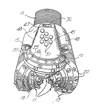
FIGURE 1 is a perspective view of a rock bit constructed according to the principles
of this invention; and
FIG. 2 is a partial cross-section of the rock bit illustrated in FIG. 1.
21~9273
- 1 Detailed Des~ ,tion
A rock bit constructed according to principles of this invention comprises a steel body
10 having three cutter cones 11 mounted on its lower end. A threaded pin 12 is at the upper
end of the bit body for assembly of the rock bit onto a drill string for drilling oil wells or
5 the like. A plurality of cemented tungsten carbide inserts 13 are pressed into holes in the
surfaces of the cutter cones for bearing on the rock formation being drilled. Nozzles 15 in
the bit body introduce drilling fluid into the space around the cutter cones for cooling and
carrying away formation chips drilled by the bit.
FIG. 2 is a fragmentary longitlldin~l cross-section of the rock bit, extending radially
10 from the rotational axis 14 of the rock bit through one of the three legs on which the cutter
cones 11 are mounted. Each leg includes a journal pin 16 extending downwardly and
radially inwardly on the rock bit body. The journal pin includes a cylindrical bearing surface
having a hard metal insert 17 on a lower portion of the journal pin. The hard metal insert
is typically a cobalt or iron-based alloy welded in place in a groove on the journal leg and
15 having a substantially greater hardness that the steel forming the journal pin and rock bit
body.
An open groove 18 is provided on the upper portion of the journal pin. Such a groove
may, for example, extend around 60% or so of the chculllfelcl1ce of the journal pin, and the
hard metal insert 17 can extend around the rem~ining 40% or so. The journal pin also has
20 a cylindrical nose 19 at its outer end.
Each cutter cone 11 is in the form of a hollow, generally-conical steel body having
cemented tungsten carbide inserts 13 pressed into holes on the external surface. For long
life, the inserts may be tipped with a polycrystalline diamond layer. Such tungsten carbide
inserts provide the drilling action by engaging a subterranean rock formation as the rock bit
25 is rotated. Some types of bits have hard-faced steel teeth milled on the outside of the cone
instead of carbide inserts.
A circumferential row of inserts 20 near the base of the cone drill formation adjacent
to the periphery or "gage" of the borehole. A row of heel row inserts are pressed into an
adjacent circumferential surface of the cone. The outer faces of the heel row inserts bear
30 against the wall of the borehole. The heel row inserts are on the gage diameter of the rock
bit and together with the gage row inserts assure that the borehole is drilled at full gage.
The cavity in the cone contains a cylindrical bearing surface including an all-minllm
bronze insert 21 deposited in a groove in the steel of the cone or as a floating insert in a
groove in the cone. The all1min-lm bronze insert 21 in the cone engages the hard metal insert
35 17 on the leg and provides the main bearing surface for the cone on the bit body. A nose
button 22 is between the end of the cavity in the cone and the nose 19 of the journal pin and
carries the principal thrust loads of the cone on the journal pin. A bushing 23 surrounds the
nose and provides additional bearing surface between the cone and journal pin. Other types
- . 2159~73
- 1 of bits, particularly for higher rotational speed applications, have roller bearings instead of
the exemplary journal bearings illustrated herein.
A plurality of bearing balls 24 are fitted into complementary ball races in the cone and
on the journal pin. These balls are inserted through a ball passage 26, which extends through
5 the journal pin between the bearing races and the exterior of the rock bit. A cone is first
fitted on the journal pin, and then the bearing balls 24 are inserted through the ball passage.
The balls carry any thrust loads tending to remove the cone from the journal pin and thereby
retain the cone on the journal pin. The balls are retained in the races by a ball retainer 27
inserted through the ball passage 26 after the balls are in place. A plug 28 is then welded
10 into the end of the ball passage to keep the ball retainer in place.
A variety of other bearing arrangements and materials may be used in other
embodiments of rock bits and the specific details of the cones or cone mounting means do
not form part of this invention.
In high performance rock bits, the bearing surfaces between the journal pin and the
15 cone are lubricated by a grease. Preferably, the interior of the rock bit is evacuated and
grease is introduced through a fill passage (not shown). The grease thus fills the regions
adjacent the bearing surfaces plus various passages and a grease reservoir, and air is
essentially excluded from the interior of the rock bit.
The grease reservoir comprises a cavity 30 in the rock bit body, which is connected
20 to the ball passage 26 by a lubricant passage 31. Grease also fills the portion of the ball
passage adjacent the ball retainer, the open groove 18 on the upper side of the journal pin,
and a diagonally extending passage 32 therebetween. Grease is retained in the bearing
structure by a resilient seal in the form of an O-ring 33 between the cone and journal pin.
A conventional pressure compensation subassembly 29 is included in the grease
25 reservoir 30. The subassembly, the details of which are not illustrated, comprises a metal
cup with an opening at its inner end. A flexible rubber bellows or "boot" extends into the
cup from its outer end. The bellows is held in place by a cap with a vent passage. The
pressure compensation subassembly is held in the grease reservoir by a snap ring. If desired,
a pressure relief check valve can also be provided in the grease reservoir for relieving over-
30 pressures in the grease system that could damage the O-ring seal.
When the rock bit is filled with grease, the bearings, the groove 18 on the journal pin,
passages in the journal pin, the lubrication passage 31, and the grease reservoir on the
outside of the bellows are filled with grease. If the volume of grease expands due to heating,
for example, the bellows is compressed to provide additional volume in the sealed grease
35 system, thereby preventing accumulation of excessive pressure. High pressure in the grease
system can damage the O-ring seal 33 and permit drilling fluid or the like to enter the
bearings. Such material is abrasive and can quickly damage the bearings. Conversely, if
the grease volume should contract, the bellows can expand to prevent low pressure in the
215~87~
1 sealed grease system, which could cause flow of abrasive and/or corrosive substances past
the O-ring seal.
The lower edge 46 of the leg of a rock bit is rounded where it covers the base of a
cutter cone and because of this shape the three faces of the bit body are commonly referred
5 to as shirttails 45. In this embodiment the outer chculllfelelllial surface of the shirttail tapers
gradually inwardly above the lower edge to a shoulder 47 just below the grease reservoir
near the pin end of the bit. A typical taper angle A is about 1 to 5 degrees. Some bits have
no taper on the shirttail and others may have shallow steps along the length of the shirttail
to, in effect, provide a taper.
Preferably the tip of the shirttail and edge of the shoulder are protected with a layer
of wear resistant hardfacing (not shown) brazed to the surface of the steel. A recessed
channel 48 extends longit~l~lin~lly between the shirttail portions of the bit body towards the
pin end. The drilling fluid nozzles 15 are typically located in this channel. If desired,
extended nozzles may be used for ejecting drilling fluid closer to the space between adjacent
cutter cones. Regardless of where ejected, drilling fluid carrying particles of drilled
formation passes upwardly through the channels and through the annulus between the shirttail
portions of the bit body and the wall of the borehole.
A plurality of bearing inserts 51 are pressed into the bit body in the gradually tapering
portion of the leg between the recesses. The lowermost of the bearing inserts 52 is
approximately half way between the lowermost tip of the curved edge of the shirttail and the
shoulder 47. The balance of the bearing inserts are located between the lowermost insert and
the shoulder.
The inserts are placed in this location so that there is sufficient steel between the
inserts and the grease passage 31 between the reservoir and bearing surfaces for ret~ining the
inserts in the insert holes. The bearing inserts are also spaced apart from the grease
reservoir so that heat generated by friction of the bearing inserts against the borehole wall
is also spaced apart from the reservoir, thereby helping assure that the grease is not
overheated. A similar location is used when there is no grease reservoir, for example, in an
air cooled drill bit with open bearings.
The ends of the bearing inserts protrude laterally (not necessarily radially) from the
surface of the bit body so that their protruding ends are substantially on the gage diameter
of the bit. The protruding ends of the inserts are rounded. Thus, the bearing inserts bear
against the borehole wall for stabilizing the bit. The rounded ends on the bearing inserts
prevent appreciable reaming of the borehole, which would effectively lose the desired
stabilization. Although illustrated as generally hemispherical, a longer radius or
asymmetrical rounding may be used.
The protruding bearing inserts are spaced apart so that drilling fluid flows around the
inserts and up the annulus. Flow around the inserts helps remove frictional heat and helps
2159873
~ protect the bit from overhe~ting. Furthermore, the absence of a stabilization pad also avoids
the effect of a "paddle" rotating in the hole. Particles in the drilling fluid do not pack around
the spaced apart protruding inserts the way it does around a stabilization pad. Disrupted flow
which erodes the cap and the grease reservoir may also be avoided. The rounded bearing
5 inserts are not found to wear to form a ledge that can hang up on shoulders in a borehole
wall.
Although, only one embodiment of an improved rock bit with stabilization has been
described and illustrated herein, many modifications and variations will be apparent to those
skilled in the art. For example, bearing inserts may be used in rock bits with milled tooth
10 cutters instead of the insert cutter cones described herein. The bearing inserts may have a
layer of polycrystalline diamond on the protruding ends for minimi~inp~ wear of the inserts.
Accordingly, it is to be understood that within the scope of the appended claims, this
invention may be practiced otherwise than as specifically described.