Language selection

Search

Patent 2159924 Summary

Third-party information liability

Some of the information on this Web page has been provided by external sources. The Government of Canada is not responsible for the accuracy, reliability or currency of the information supplied by external sources. Users wishing to rely upon this information should consult directly with the source of the information. Content provided by external sources is not subject to official languages, privacy and accessibility requirements.

Claims and Abstract availability

Any discrepancies in the text and image of the Claims and Abstract are due to differing posting times. Text of the Claims and Abstract are posted:

  • At the time the application is open to public inspection;
  • At the time of issue of the patent (grant).
(12) Patent: (11) CA 2159924
(54) English Title: FOLDING TABLE
(54) French Title: TABLE PLIANTE
Status: Term Expired - Post Grant Beyond Limit
Bibliographic Data
(51) International Patent Classification (IPC):
  • A47B 3/08 (2006.01)
(72) Inventors :
  • SOPER, DOUGLAS (Canada)
(73) Owners :
  • INO-PRODUCTS INC.
(71) Applicants :
  • INO-PRODUCTS INC. (Canada)
(74) Agent: GOWLING WLG (CANADA) LLP
(74) Associate agent:
(45) Issued: 1999-02-09
(22) Filed Date: 1993-12-07
(41) Open to Public Inspection: 1995-04-16
Examination requested: 1997-12-16
Availability of licence: N/A
Dedicated to the Public: N/A
(25) Language of filing: English

Patent Cooperation Treaty (PCT): No

(30) Application Priority Data:
Application No. Country/Territory Date
08/136,186 (United States of America) 1993-10-15

Abstracts

English Abstract


A folding table has a table top with an upper working surface and an
underside, the underside having at least one rearwardly located leg retainer and at
least one forwardly located strut retainer. A leg assembly has an elongated
connecting member and a pair of legs extending from opposite ends of the
connecting member, each leg having a foot member extending from a lower end
thereof remote from the connecting member. An angularly movable strut is
pivotally secured at the rear to at least one of the legs and is releasably engageable
at the front with the strut retainer. The strut is angularly movable between a
working position in releasable engagement with the strut retainer to maintain the
tabletop in a working position and a retracted position between the legs when
released from the strut retainer. The or each leg retainer retains the connecting
member in engagement therewith while permitting angular movement of the
table top between a working position and a folded position in which the table
top is substantially parallel to the legs.


French Abstract

Cette invention concerne une table pliante dont le plateau comporte du côté arrière de sa face inférieure au moins une fixation de piètement et de l'autre côté au moins une pièce d'appui d'étrésillon. Le piètement se compose d'un raccord allongé entre une paire de pieds qui se prolongent par une partie horizontale s'éloignant dudit raccord. Un étrésillon mobile autour d'axe horizontal prévu dans au moins un des pieds, qui sont situés du côté arrière de la table, se cale de façon amovible dans la pièce d'appui d'étrésillon prévue sur la moitié avant de la face inférieure du plateau. L'étrésillon pivote entre une position de travail où il est calé de façon amovible dans la pièce d'appui d'étrésillon pour maintenir le plateau à l'horizontale et une position escamotée entre les pieds de la table, une fois libéré de ladite pièce d'appui d'étrésillon. Le raccord susmentionné est monté dans la ou les fixations de piètement solidaire(s) du plateau de façon à constituer un axe autour duquel le plateau peut pivoter entre une position horizontale et une position escamotée où il est sensiblement parallèle aux pieds de la table.

Claims

Note: Claims are shown in the official language in which they were submitted.

I CLAIM:
1. A folding table comprising:
a table top having an upper working surface and an underside,
said underside having at least one rearwardly located leg retainer and at least
one forwardly located strut retainer,
a leg assembly comprising an elongated connecting member and a pair of
straight legs extending from opposite ends of the connecting member, each leg
having a foot member extending perpendicular from a lower end thereof remote
from the connecting member whereby in use the legs are vertical and the foot
members extend forwardly therefrom, and
an angularly movable strut pivotally secured at the rear to at least one of the
legs and releasably engageable at the front with the strut retainer,
said strut being angularly moveable between a working position in releasable
engagement with the strut retainer to maintain the tabletop in a working position
and a retracted position between the legs when released from the strut retainer,each leg retainer retaining the connecting member in engagement therewith
while permitting angular movement of the table top between a working position and
a folded position in which the table top is substantially parallel to the legs,
said legs each having upper and lower portions in telescoping
-8-

engagement, the lower leg portions being securable at different longitudinal
positions relative to the upper portions to vary the length of the legs,
the lower leg portion being angularly movable relative to the upper leg
portions about the longitudinal axes of the legs to enable the lower leg portions
to be securable in working positions in which the foot members are parallel to
one another and folded positions in which the foot members extend in opposite
directions side-by-side one another.
2. A folding table according to claim 1 wherein the underside of the table
top has a laterally-spaced pair of said rearwardly located leg retainers.
3. A table top according to claim 1 wherein each leg retainer retains the
connecting member in releasable snapping engagement therewith.
4. A table top according to claim 1 wherein each leg retainer comprises a
closely spaced pair of substantially identical leg retainer members which each
retain the connecting member in engagement therewith.
5. A folding table according to claim 1 wherein the underside of the table
top has a laterally-spaced pair of said forwardly located strut retainers.
6. A folding table top according to claim 1 wherein each strut retainer
- 9 -

receives the strut in releasable snapping engagement therewith.
7. A folding table according to claim 1 wherein each strut retainer can
receive the strut in releasable engagement therewith at a plurality of positions
spaced from one another in a front to rear direction.
8. A folding table according to claim 1 wherein each strut retainer
comprises a closely-spaced pair of substantially identical strut retainer members
which each receive the strut in a releasable engagement therewith.
9. A folding table according to claim 1 wherein the strut comprises a pair
of laterally-spaced side members each pivotally secured at a rear end to a
respective leg and a transverse member extending between the front ends of the
side members, said transverse member being received by each strut retainer in
releasable engagement therewith in the working position.
- 10 -

Description

Note: Descriptions are shown in the official language in which they were submitted.


2 1 5~924
FOLDING TABLE
This application is a divisional of application serial no. 2,110,875 filed
December 7, 1993.
This invention relates to folding tables. There are of course many known
different kinds of folding tables. However, there is still a need for a versatile folding
table which is of simple yet attractive construction and which can be easily erected
and folded.
According to the invention, a folding table comprises a table top having an
upper working surface and an underside, the underside having at least one
rearwardly located leg retainer and at least one forwardly located strut retainer, a leg
assembly comprising an elongated connecting member and a pair of legs extending
15 from opposite ends of the connecting member, each leg having a foot member
exten~ling from a lower end thereof remote from the connecting member and an
angularly moveable strut pivotally secured at the rear to at least one of the legs and
releasably engageable at the front with the strut retainer. The strut is angularly
moveable between a working position in releasable engagement with the strut
20 retainer to maintain the table top in a working position and a retracted position
between the legs when released from the strut retainer. The or each leg retainerretains the connecting member in engagement therewith while permitting angular
movement of the table top between a working position and a folded position in

21~ 2 ~
which the table top is substantially parallel to the legs.
The underside of the table top may have a laterally-spaced pair of
rearwardly located leg retainers, and the or each leg retainer may retain the
connecting member in releasable snapping engagement thelewi~l. The or each
S leg retainer may comprise a closely spaced pair of substantially identical leg
retainer members which each retain the connecting member in engagement
thel~wilh
The underside of the table top may have a laterally-spaced pair of
forwardly located strut retainers, and the or each strut retainer may receive the
10 strut in releasable snapping engagement therewi~l. The or each strut retainer
may receive ~e strut in releasable engagement therewith at a plurality of
positions spaced from one another in a front to rear direction. The or each
strut retainer may comprise a closely-spaced pair of substantially identical strut
retainer members which each receive the strut in releasable engagement
15 therewith.
The strut may comprise a pair of laterally-spaced side members each
pivotally secured at a rear end to a respective leg and a transverse member
extending between the front ends of the side members, the transverse member
being received by the or each strut retainer in releasable engagement therewith

215992~
in the working position. The legs may each have upper and lower portions in
telescoping engagement, the lower leg portions being securable at dirrerenl
longit-l~lin~l positions relative to the upper portions to vary the length of the
legs.
S The lower leg portions may be angularly movable relative to the upper
leg portions about ~e longit~l(lin~l axes of the legs, the lower leg portions being
securable in working positions in which the foot members are parallel to one
another and folded positions in which the foot members extend in opposite
directions side-by-side one ano~er.
One embodiment of the invention will now be described, by way of
example, with referellce to the accompanying drawings, of which
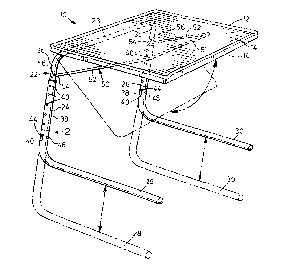
Fig. 1 is a perspective view of a folding table in accordance with one
embodiment of the invention, the table top being in a horizontal working
position,
Fig. 2 is a detailed view of the portion of a table leg indicated by the
arrow 2 in Fig. 1,
Fig. 3 is a perspective view of the table with the table top in an inclined
working position and showing ~e underside of the table top,
Fig. 4 is a perspective view of the table in the fully folded condition,
Fig. S is a sectional detailed view along the line 5-5 of Fig. 3 of a rear

~lS9~
portion of a table top showing a leg retainer and part of the leg assembly, and
Fig. 6 is a similar view along the line 6-6 of Fig. 3 of a front portion of
the table top showing a strut retainer and part of the strut.
Referring to the drawings, a folding table 10 has an integrally molded
S plastic table top 12 in the form of a rectangular panel with rounded corners, the
table top 12 having an upper working surface 14 and an underside 16. The
underside 16 has a laterally-spaced pair of rearwardly located integral leg
retainers 18 and a laterally-spaced pair of forwardly located integral strut
retainers 20. A leg assembly 22 of tubular steel comprises a transverse
connecting member 23 and a pair of legs straight 24, 26 extending from
opposite ends of the connecting member 23, each leg 24, 26 having an
elongated foot member 28, 30 respectively ext~n~1ing perpendicularly from the
lower end thereof.
Each leg retainer 18 comprises a closely-spaced pair of identical leg
15 retainer members 32 which each have hook portions 34 to retain the connecting
member 23 in releasable snapping engagement therewi~l and permit the table
top 12 to be moved angularly relative to the leg assembly 22 in a manner which
will be described in more detail later.
Each leg 24, 26 has upper and lower portions 36, 38 in telescopic

~15g9~4
engagement, the lower leg portions 38 being slidable over the upper leg
portions 36. Each upper leg portion 36 is integral with the relevant end of the
connecting member 23, and each lower leg portion 38 is integral with the
respective foot member 28, 30, the foot members 28, 30 thus also being of
S tubular steel. Each lower leg potion 38 has a series of vertically-spaced
apertures 40 on its laterally outer and inner sides, and each upper leg portion
36 contains a resiliant U-shaped catch member 42 adjacent its lower end as
shown in Fig. 2. The catch member 42 has a pair of projections 44 which
project through apertures 46 in the upper leg portion 38 on opposite sides
10 thereof. The projections 44 are snappingly engageable in selected pairs of
apertures 40 in the lower leg portions 38 to enable the length of the legs 24, 26
to be adjusted as indicated in dotted outline in Fig. 1.
For folding purposes, as will be described in more detail later, the lower
leg portions 38 can be rotated about their longilll~lin~l axis to the laterally-
15 inwardly extending positions shown in dotted outline in Fig. 3. Each lower legportion 38 also has an aperture 48 on a front surface so that one of the
projections 44 can snap thereinto to retain the lower leg portions 38 in the
inwardly folded position.
An angularly movable strut 50 is pivotally secured at the rear to the
20 upper leg portions 36. The strut 50 is a metal rod bent to provide a transverse

2ls9g~il
member 51 at the front and a pair of laterally-spaced side members 52
extending rearwardly from opposite ends thereof. Each side member 52 has
a bent free end portion 54 at the rear extending into an aperture 56 in the
respective upper leg portion 36 to pivotally secure the strut 50 thereto. Each
5 strut retainer 20 comprises a closely-spaced pair of identical strut retainer
member 58 which each have a series of hook portions 60 spaced from one
another in the front to rear direction which can each retain the transverse strut
member 51 in releasable snapping engagement therewith.
Fig. 1 shows the table in the fully erected position with the table top 12
10 horizontal, i.e. perpendicular to the legs 24, 26. It will be understood that to
retain the table top 12 in the horizontal position, the transverse strut member
51 is snapped in to the strut retainer hook portion 60 furthest from the front of
the table top 12. The foot members 28, 30 extend forwardly from the vertical
legs 24, 26 beneath the table top 12. If it is desired to position the table top
15 12 in an inclined manner as indicated in dotted outline in Fig. 1 and shown in
more detail in Fig. 3, the transverse strut member 51 is snapped into strut
hooked portions 60 nearer the front of the table top 12.
The table can be completely folded as shown in Fig. 4, by swinging the
foot members 28, 30 inwardly as previously described and, releasing the
20 transverse strut retainer 51 from the retainer hook portions 60 and pe-",il~;n~

21~992~
the strut 50 to pivot downwardly to a near vertical position. The table top 12
can then be pe~nittecl to swing dowllw~dly in the same manner so as to be
parallel to the legs 24, 26.
The foot members 28, 30 can be left in the forwardly extending position
S shown in Figs. 1 and 3, and the strut 50 and table top 12 put in the near
vertical position so that the members 28, 30 can be slid under the side or rear
of a chair or couch with the table top 12 adjacent the side or rear of the chair
or couch. The table is thus then readily accessible for future use, it merely
being necessary to slide the table out and position the table top 12 by means of
10 the strut 50.
It will be clear from the above description of a prefeled embodiment that
the present invention provides a folding table which is of simple yet attractive
construction and which can be easily erected and folded.
Other embodiments of the invention will be readily apparellt to a person
15 skilled in the art, the scope of the invention being defined in the appended
claims.

Representative Drawing
A single figure which represents the drawing illustrating the invention.
Administrative Status

2024-08-01:As part of the Next Generation Patents (NGP) transition, the Canadian Patents Database (CPD) now contains a more detailed Event History, which replicates the Event Log of our new back-office solution.

Please note that "Inactive:" events refers to events no longer in use in our new back-office solution.

For a clearer understanding of the status of the application/patent presented on this page, the site Disclaimer , as well as the definitions for Patent , Event History , Maintenance Fee  and Payment History  should be consulted.

Event History

Description Date
Inactive: Expired (new Act pat) 2013-12-07
Inactive: Office letter 2008-11-12
Inactive: Entity size changed 2002-10-02
Grant by Issuance 1999-02-09
Inactive: Final fee received 1998-10-20
Pre-grant 1998-10-20
Notice of Allowance is Issued 1998-10-09
Letter Sent 1998-10-09
Inactive: Approved for allowance (AFA) 1998-10-01
Inactive: RFE acknowledged - Prior art enquiry 1998-03-18
Inactive: Status info is complete as of Log entry date 1998-03-18
Inactive: Application prosecuted on TS as of Log entry date 1998-03-18
Request for Examination Requirements Determined Compliant 1997-12-16
All Requirements for Examination Determined Compliant 1997-12-16
Application Published (Open to Public Inspection) 1995-04-16

Abandonment History

There is no abandonment history.

Maintenance Fee

The last payment was received on 1998-10-28

Note : If the full payment has not been received on or before the date indicated, a further fee may be required which may be one of the following

  • the reinstatement fee;
  • the late payment fee; or
  • additional fee to reverse deemed expiry.

Please refer to the CIPO Patent Fees web page to see all current fee amounts.

Owners on Record

Note: Records showing the ownership history in alphabetical order.

Current Owners on Record
INO-PRODUCTS INC.
Past Owners on Record
DOUGLAS SOPER
Past Owners that do not appear in the "Owners on Record" listing will appear in other documentation within the application.
Documents

To view selected files, please enter reCAPTCHA code :


To view images, click a link in the Document Description column. To download the documents, select one or more checkboxes in the first column and then click the "Download Selected in PDF format (Zip Archive)" or the "Download Selected as Single PDF" button.

List of published and non-published patent-specific documents on the CPD .

If you have any difficulty accessing content, you can call the Client Service Centre at 1-866-997-1936 or send them an e-mail at CIPO Client Service Centre.


Document
Description 
Date
(yyyy-mm-dd) 
Number of pages   Size of Image (KB) 
Description 1998-07-11 7 235
Claims 1998-07-11 3 86
Drawings 1998-07-11 3 102
Claims 1998-07-10 1 32
Description 1998-07-10 1 35
Abstract 1998-07-10 1 27
Cover Page 1999-02-04 1 63
Abstract 1998-05-01 1 27
Description 1998-05-01 1 35
Claims 1998-05-01 1 32
Cover Page 1998-07-21 1 13
Representative drawing 1999-02-04 1 12
Acknowledgement of Request for Examination 1998-03-18 1 173
Commissioner's Notice - Application Found Allowable 1998-10-09 1 163
Fees 2003-11-13 1 31
Correspondence 1998-10-20 1 35
Fees 1998-10-28 1 43
Fees 2001-10-18 1 30
Fees 2000-11-20 1 32
Fees 2002-09-24 1 31
Fees 1997-10-17 1 44
Fees 1999-11-10 1 39
Fees 2004-11-08 1 29
Fees 2005-10-07 1 34
Fees 2006-11-03 1 31
Fees 2007-10-18 2 71
Correspondence 2008-11-12 1 17
Fees 2008-10-24 1 32
Fees 2008-10-20 2 48
Fees 2009-10-16 1 33
Fees 1995-10-05 1 47
Fees 1996-10-10 1 54