Language selection

Search

Patent 2160096 Summary

Third-party information liability

Some of the information on this Web page has been provided by external sources. The Government of Canada is not responsible for the accuracy, reliability or currency of the information supplied by external sources. Users wishing to rely upon this information should consult directly with the source of the information. Content provided by external sources is not subject to official languages, privacy and accessibility requirements.

Claims and Abstract availability

Any discrepancies in the text and image of the Claims and Abstract are due to differing posting times. Text of the Claims and Abstract are posted:

  • At the time the application is open to public inspection;
  • At the time of issue of the patent (grant).
(12) Patent: (11) CA 2160096
(54) English Title: DOOR LATCH OPERATING MECHANISM
(54) French Title: MECANISME ACTIONNEUR DE VERROU DE PORTE
Status: Deemed expired
Bibliographic Data
(51) International Patent Classification (IPC):
  • E05F 11/00 (2006.01)
  • E05B 1/00 (2006.01)
(72) Inventors :
  • WARTIAN, GEORGE (United States of America)
(73) Owners :
  • WARTIAN, GEORGE (United States of America)
(71) Applicants :
(74) Agent: MACRAE & CO.
(74) Associate agent:
(45) Issued: 2000-08-15
(22) Filed Date: 1995-10-06
(41) Open to Public Inspection: 1997-01-19
Examination requested: 1998-03-26
Availability of licence: N/A
(25) Language of filing: English

Patent Cooperation Treaty (PCT): No

(30) Application Priority Data:
Application No. Country/Territory Date
08/503,505 United States of America 1995-07-18

Abstracts

English Abstract


Door latch-operating mechanism for retracting a door
latch. A rotary shaft is mounted in a housing and is adapted
to retract a latch when rotated. The shaft is turned by a handle
on the outer end of the shaft. A tube is sleeved on the shaft
between the handle and housing. The housing and handle are
solid brass forgings. The tube is also solid brass. Any wear
of the handle will not be noticed since it is solid brass rather
than being made of some less attractive metal plated with brass.
The shaft is completely covered and concealed by the brass
housing, handle and tube.


Claims

Note: Claims are shown in the official language in which they were submitted.


THE EMBODIMENTS OF THE INVENTION IN WHICH AN EXCLUSIVE PROPERTY OR
PRIVILEGE IS CLAIMED ARE DEFINED AS FOLLOWS:

1. Door latch operating mechanism for retracting a door latch, comprising a
solid
brass housing, a cylindrical shaft, means mounting said shaft in said housing
for rotation, said
shaft adapted to be operably connected to a door latch to retract the same
upon rotation thereof,
said shaft projecting outwardly from said housing and having an outer end
spaced from said
housing, an elongated solid brass handle for rotating said shaft, means
attaching said handle to
the outer end of said shaft, and a solid brass tube sleeved on said shaft
between said housing
and said handle, said means attaching said handle to the outer end of said
shaft comprising a
flange integrally formed on the outer end of said shaft and projecting beyond
an outer
circumference of said shaft, said flange having means providing a hole, and a
pin integrally
formed on said handle extending into said hole, said pin being staked to lock
said pin in said
hole.
2. Door latch mechanism as defined in claim 1, wherein said handle is U-shaped
in
cross-section having a top wall and laterally spaced side walls extending
downward from said
top wall and defining a trough adjacent the inner end thereof, said flange
extending into said
trough, said side walls extending beneath said flange so the said flange is
completely concealed
from view when said handle is viewed from the top and side.
3. Door latch mechanism as defined in claim 2, wherein said shaft is
completely
covered by said housing, tube and handle.
4. Door latch mechanism as defined in claim 3, wherein said handle and housing
are
forgings.


1

Description

Note: Descriptions are shown in the official language in which they were submitted.


~lB~g6
DOOR LATCR OPERATING M~r.RANT.~M
Field of the Invention
This invention relates generally to door latches and
refers more particularly to a docr latch operating mechanism.

.

Background and Summary
In many door latch assemblies, the latch is retracted
by a rotary shaft. The shaft is turned by a handle. The handle
and shaft may be formed as a one-piece zinc casting. For the
sake of appearance, the handle may be plated with brass. The
problem with brass plate, however, is that in short time it
wears away and exposes the base metal.
In accordance with the present invention, the handle
is made entirely of brass. Because a metal mold will not
withstand the high temperatures necessary to cast brass, the
handle is preferably made as a forging. The shaft, usually of
a less expensive metal such as zinc, may be cast, and preferably
has a flange which is staked tc the handle. A brass tube is
preferably sleeved on the shaft. The entire unit, including a
brass housing in which the shaft is mounted, is attractive and
may be used indefinitely without showing any evidence of wear.


Z16 0D~
One object of this invention is to provide a door
latch operating mechanism having the foregoing features.
Another object is to provide a door latch operating
mechanism which is composed of a relatively few simple parts,
is rugged and durable in use, and is capable of being readily
manufactured and easily assembled.
Other objects, features and advantages of the
invention will become more apparent as this description proceeds,
especially when considered with the accompanying drawings.

Brief Description of the Drawings
FIG. 1 is a plan view of a door latch assembly
constructed in accordance with the invention.
FIG. 2 is a view partly in section taken on the line
2--2 in FIG. 1.
FIG. 3 is a view partly in section taken on the line
3--3 in FIG. 2.
FIG. 4 is a view taken on the line 4--4 in FIG. 2.
FIG. 5 is a sectional view taken on the line 5--5 in
FIG. 3.


2~60~B
Detailed De~cription
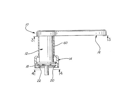
F~eferring now more particularly to the drawings, the
door latch assembly lO comprises a rotary, cylindrical shaft
12 ~ournalled for rotation in a housing 14, and a handle 16 for
turning the shaft. A disc 18 affixed to the shaft has
diametrically opposed pins 20 and 22 engageable with the
respective abutments 24 and 26 on the latch 28 to retract the
latch when the shaft is rotated.
The handle 16 is an elongated member generally U-
shaped in cross-section having a top wall 30 and laterally
spaced side walls 32 and 34. The side walls merge at the ends
of the handle, providing a circular recess 36 at the inner end.
The recess 36 at the inner end of the handle 16 fits over the top

of the shaf t 12 .
The outer end of the shaft 12 has an integral, laterally
outwardly extending flange 40 which extends into the trough 42
defined by the top and side walls of the handle 16 ad~acent to
recess 36. The side walls 32 and 34 of the handle extend below
the flange 40 so that the flange is completely concealed from
view when the unit is viewed ~rom the top or the side. The top
wall 30 has an integral pin 50 which extends perpendicular
thereto into the trough. The pin 50 extends through a hole 52
in the flange 40 and is staked to provide a permanent and rigid
connect i on .

--3--

~160~9~
A tube 60 is sleeved on the shaft 12 between the
housing 14 and the handle 16.
Both the handle 16 and the housing 14 are solid brass,
preferably forgings. The tube 60 is also solid brass.
The shaf t 12 may be made of any 8Ui table, usually
less expensive material such, for example, as zinc, and may be
formed as a ca3ting.
The entire assembly is attractive in appearance, since
all of the exposed parts, namely, the housing 14, handle 16 and
tube 60 are formed of brass. The 3haft 12 is completely covered
and concealed by the housing, tube and handle. The assembly can
be used for a long period of time without showing any evidence
of wear. Any actual wear of the handle is unnoticeable because
the handle is made of solid brass.

Representative Drawing
A single figure which represents the drawing illustrating the invention.
Administrative Status

For a clearer understanding of the status of the application/patent presented on this page, the site Disclaimer , as well as the definitions for Patent , Administrative Status , Maintenance Fee  and Payment History  should be consulted.

Administrative Status

Title Date
Forecasted Issue Date 2000-08-15
(22) Filed 1995-10-06
(41) Open to Public Inspection 1997-01-19
Examination Requested 1998-03-26
(45) Issued 2000-08-15
Deemed Expired 2008-10-06

Abandonment History

There is no abandonment history.

Payment History

Fee Type Anniversary Year Due Date Amount Paid Paid Date
Application Fee $0.00 1995-10-06
Maintenance Fee - Application - New Act 2 1997-10-06 $100.00 1997-09-22
Request for Examination $400.00 1998-03-26
Maintenance Fee - Application - New Act 3 1998-10-06 $100.00 1998-09-17
Maintenance Fee - Application - New Act 4 1999-10-06 $100.00 1999-09-22
Final Fee $300.00 2000-05-12
Maintenance Fee - Patent - New Act 5 2000-10-06 $75.00 2000-09-21
Maintenance Fee - Patent - New Act 6 2001-10-08 $75.00 2001-09-21
Maintenance Fee - Patent - New Act 7 2002-10-07 $275.00 2002-10-18
Maintenance Fee - Patent - New Act 8 2003-10-06 $75.00 2003-09-22
Maintenance Fee - Patent - New Act 9 2004-10-06 $100.00 2004-09-21
Maintenance Fee - Patent - New Act 10 2005-10-06 $125.00 2005-09-21
Maintenance Fee - Patent - New Act 11 2006-10-06 $125.00 2006-09-18
Owners on Record

Note: Records showing the ownership history in alphabetical order.

Current Owners on Record
WARTIAN, GEORGE
Past Owners on Record
None
Past Owners that do not appear in the "Owners on Record" listing will appear in other documentation within the application.
Documents

To view selected files, please enter reCAPTCHA code :


To view images, click a link in the Document Description column. To download the documents, select one or more checkboxes in the first column and then click the "Download Selected in PDF format (Zip Archive)" or the "Download Selected as Single PDF" button.

List of published and non-published patent-specific documents on the CPD .

If you have any difficulty accessing content, you can call the Client Service Centre at 1-866-997-1936 or send them an e-mail at CIPO Client Service Centre.


Document
Description 
Date
(yyyy-mm-dd) 
Number of pages   Size of Image (KB) 
Representative Drawing 2000-08-04 1 6
Cover Page 1996-10-28 1 10
Abstract 1996-10-28 1 12
Description 1996-10-28 4 73
Claims 1996-10-28 2 32
Drawings 1996-10-28 1 21
Claims 1998-08-19 1 41
Cover Page 2000-08-04 1 29
Representative Drawing 1998-05-20 1 5
Correspondence 2000-07-28 2 55
Correspondence 2000-05-12 1 28
Assignment 1995-10-06 4 114
Prosecution-Amendment 1998-03-26 7 194