Note: Descriptions are shown in the official language in which they were submitted.
_ 2160. ~8
P:~OP~PATAP192 9~23~94
10
Prosthesis Fixturing Device
is
BACKGROUND
This invention relates to prothesis fixturing devices,
more particularly, fixturing stems for attaching a prothesis
to a bone, e.g., a tibia, and a prothesis with an
zo articulating bearing surface.
Many methods have been employed to fixture prostheses to
bone, including screws, press fit, bone cement and biological
fixation into porous surfaces. Currently bone cement and
biological ingrowth are the preferred means of fixation.
2s Fixturing surface geometries used include plates, fins, stems
and pegs of various cross-sections. Fins form projections
which in the prior art need bone preparation such as mating
slots in the bone to receive the fins. This is undesirable
as it entails further surgical procedures in addition to the
30 prescribed procedures for preparing the bone for a tapered
stem without such fins. Reference is made, for example, to
brochures nj LCS~ Tricompartmental Knee System with
Porocoat~, Surgical Procedure by Frederick F. Buechel, 1993,
Biomedical Engineering Trust, South Orange, NJ . and
3s Biomechanics and Design Rationale; New Jersey LCS~ Knee
Replacement System by Michael J. Pappas et a1.1993,
-1-
_. ~16Q~ 9S
,.
Biomedical Engineering Trust which illustrate fixturing
geometries and procedures for knee protheses.
The problem in these protheses is to securely attach a
prothesis to bone, and yet permit the prothesis to be removed
s from the bone without damage thereto. More particularly, a
problem is known in using cement with such protheses. For
example, if the cement interlocks with depressions in the
mating prothesis surface, then such interlocking may cause
bone damage when the prothesis is removed. Such removal is
o sometimes necessitated by failure or otherwise degeneration
of the prothesis-bone configuration.
Another problem encountered during the insertion
procedure in attaching the prothesis via a fixturing device
to the bone is alignment. Known fixturing stems are
1s different shapes including conical, rectangular, fin among
others. The mating bone cavity is similarly shaped as the
corresponding stem. There is a gap between these elements
when engaged to accommodate cement. These elements need to
be axially aligned during the insertion process. The gap
2o could cause misalignment of the elements during insertion or
later during curing of the cement. Any misalignment could
cause problems with the user of the joint, especially a knee
prothesis where motion directions can be critical. Thus, it
is important that the mating elements remain fixed in place
2s and properly aligned during insertion and curing of the
cement.
A still further problem is loosening of the prothesis
from the bone to which the prothesis is attached during use.
The present inventor recognizes a need for improving
3o torsional resistance between the fixturing device and the
bone to which the device is attached, stability during curing
of the cement or biological ingrowth, and ease of
implantation and removal the device in the event of failure.
A prothesis fixturing device according to one embodiment
3s of the present invention attaches a prothesis component
-2-
2g 60~ ~~
including a bearing to a bone, the bone having a resected
surface. The device is subject to torque loads about an axis
transverse the resected surface, the torque loads tending to
loosen the device relative to the bone. The device comprises
s a tray having a first surface for receiving the bearing and
a second opposing surface and at least one wall depending
from the opposing second surface for abutting the resected
surface and for forming at least one recessed compartment
with the second surface at a depth of at least 1.50 mm to
io receive a cement :for bonding the tray to the bone at the
resected surface, the at least one wall having a
configuration for providing resistance to torque loads on the
tray about the axis.
In a further embodiment a prothesis fixturing device
15 attaches a prothesis component including a bearing to a bone,
the bone having a resected surface and a cavity defining a
longitudinal first axis transverse the surface, the cavity
being in communication with the surface at a cavity edge, the
surface and cavity for receiving the device. The device
2o comprises a stem for receiving a prothesis and defines a .
second longitudinal axis. Centering means are integral with
the stem forming a one piece construction for engaging the
cavity edge to center the stem relative to the cavity first
axis during axial insertion of the stem into the cavity. .
2s In accordance with a further embodiment the stem has a
plurality of axially extending channels having a bottom
surface, the stem having a peripheral surface, the channel
bottom surfaces intersecting the stem peripheral surface at
a channel region distal the tray, the bottom surfaces each
3o having a radial dimension to the second axis at least as
great as the radial dimension of the intersections.
A stem according to a still further embodiment depends
from a tray and defines a second longitudinal axis, the stem
being dimensioned for insertion into the cavity with the axes
3s substantially parallel, the stem having a cylindrical axially
-3-
CA 02160198 2003-06-13
extending portion proxi.ma 1 the tr'a'y and a comical portion
axially extending from the cylinctr.i_ca C port-i.on distal t=he
tray.
In a broad aspect, then, the present. invention relat:es
to a prosthesits fixturing device fo.r att:aching a prosthe:~is
component inclu~~ing a bearing to a bone, said bone having a
resected surfaced, said bone further having s:r cavity extending
therein, said cavity haring an edge at: t:he re:>ected surface
of the bone, sa_Ld cavity defining an axis aligned transverse
to the resected surface, said resected :7urface arud said cavity
being for receiving said device, raid device being subject to
torque loads about said ,:;axis transverse the re:>ected surface,
said torque loads tendim:~ t.o Loosen the device relative to t:he
bone, said device compr'i.sing: a tra~,~~ having a first surface
f_or receiving said bearing and a second opposing surface, t:he
first surface oi_ the tra~i,r defining an outer periphery; a stem
depending from said tray, said stem having a longitudinal
axis, said stem further inaving a circular cylindrical portvon
disposed Proximally to said tray anc~ a conical portion
depending from i~he circti.a<~r cy.iindric:al p<.~rtion and disposed
distally of the tray, sai.c circular cyl_Lr~dric:al portion and
said conical portion of said stem be_Lnd ciimensi.oned to be
received .in said bone c~,vi.ty sucr~ trs.at tha.e second surfar_e of
the tray abuts t:he r_esecl~ed surface of the bone when the stem
is received in the bone cavity, said stem further comprising
at least three Equally .paced projections extending radially
outwardly from said stem, said projections having edges
disposed distally fronu said tray, said edges of said
projections being inclined toward the ~;tem axis and toward an
End of the stem distal~~,~ of the tray, said edges of said
projections bei.:ng dimen::,ioned to Lie on a conical surface of
revolution for abuttinc;~ the cavity edge at :.aid resect~ed
surface when said stem i_s~ i.n said cavity for centering s<~id
stem in said cavity; and at: least onf= wall dependent from i~he
second surface of the tray for abutting the resected surface
-4-
CA 02160198 2003-06-13
of the bone and for forming at .Leanest one recessed compartment
with the second surfaced c3f the t:uary at: a de~>th of at least
1.50 mm to receive a cement for bonding the tray to the bone
at the resected surfacca, said at least one wall having an
outer face aligned with thc~ outer periphery of the first
surface of the tray anc.~ an firmer face aligned substantially
parallel to the axis such that said inner. face defines a
configuration cooperating with the cement for providing
resistance to said torqi.a~: loads on said tray about said axis.
I:N THE DRAWINGS
FIGURE 1 us a sidF~ elevation view a knee prosthesis
o:f
according to iruvention;
one embodiment
of the pr<~ser~.t:
FIGURE 2 is front elevation view of the prosthesis
of
Fig. 1;
FIGURE 3 is an i>ometri.c view of tray used in the
a
embodiments Figs. 1 aand 2.;
of
FIGURE 4 is a front elevation view the embodiment
of of
the invention of Fig. 2 showing the tray
of F'ig. 3 partially
inserted into the stem receiving
a tibia bone
and aligned.
with
cavity in the bone;
FIGURE 5 is a sectional elevation of the embodiment
view
of the present invention illustrating a
channel portion of the
stem and bone;
FIGURE 6 is a sectional view of the embodiment of the
present invent ion illustrating a fi.n portion
of the stem and
bone;
FIGURE 7 is a parrt:i.aLly in section side elevation view
of a second embodiment of the present inventic>n; and
FIGURE 8 is a plan bottom view of a tray according to a
second embodiment of tine present :invention.
-9a-
CA 02160198 2003-06-13
DESCRIPTION OF THE PREFERRED EMBODIMENTS
The disclosed embodiment relates to a tibial prosthesis
of a knee replacement. 'This is given by way or example, as
other joints may be provided replacement prosthesis according
to the present invention. The knee replacement prosthesis 2
comprises a femoral compco~ent 4 and a tibial component 6. '.f'Ihe
femoral component 4 comprises a hard, corrosion resistant
metal. Preferred metals for orthopaedic applications are a
cobalt chromium alloy or a ceramic coated, titanium alloy. The
femoral component 4 ha:~s a polished art:Lc:u.lating surface
-4b-
~~.~~1~8
8. The femoral component is commercially available and does
not form any part of the present invention.
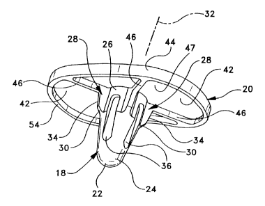
The tibial component 6 is a composite structure. It
includes a metal fixturing device 10 of the preferred
s materials mentioned above and a plastic bearing 12 secured to
the device 10 in a conventional manner by snap fit or other
locking engaging arrangements. The bearing 12 has a bearing
surface 14. The device 10 secures the component 6 to the
tibia 16. The preferred plastic for orthopaedic applications
1o is ultra high molecular weight polyethylene (UHMWPe).
The tibia 16 has a resected surface 17 and a conical
cavity 19 for receiving the device 10. The cavity 19 has a
longitudinal axis 19' transverse resected surface 17. The
stem has a longitudinal axis 32. The device 10 includes a
1s stem 18 and a tray 20. The tray 20 abuts the surface 17 and
the stem 18 is received in the cavity 19. The stem 18
includes a distal, spherical end 22, a conical center section
24, and a circular cylindrical proximal section 26. Four
fins 28 extend radially outwardly from the cylindrical
2o section 26. The fins 28 are equally spaced about the
periphery of the stem. The fins 28 are planar sheets of
uniform cross section integral with the stem and tray which
are homogeneous without connecting joints. The fins 28 have
a tapered end edge 30 which inclines toward the stem 18
2s longitudinal axis 32 and toward the distal end 22 of the
stem. In Fig. 6, the fin 28 inclination a may be about 30°
to the stem axis 32. The fins 28 also preferably have
inclined outer edges 34 which incline more gradually than
edges 30, but in the same general inclination direction
3o toward axis 32 to facilitate penetration of the fins into the
. tibia during impaction.
The fins 28 are relatively thin, having a thickness
preferably of about 2 mm. The fins 28 radially project
beyond the stem 18 cylindrical section 26 a distance d,-Fig.
3s 6, sufficient to penetrate the tibia a distance of about 1.5
-5-
21601~~
mm when the device 10 is impacted with the tibia as will be
described. This penetration amount is significant because it
is sufficiently great to provide torsional resistance of the
stem about axis 32 without damaging the tibia during
impaction. A greater penetration might cause tibia damage
whereas a lesser penetration may not provide desired
torsional resistance.
In Fig. 6, the conical cavity 19 has a diameter greater '
than that of the conical section 24 of stem 18 producing a
1o gap G' between the.stem and the tibia in cavity 19. Gap G'
provides space for cement to bond the device 10 to the tibia.
This gap G' causes alignment problems during implantation of
the stem and during curing without the presence of fins 28 as
will be discussed below.
The torsional resistance of the fins 28 help preclude
premature loosening of the device relative to the tibia. At
the same time the fin penetration into the tibia is
sufficiently small so as to not require forming corresponding
channels in the tibia for receiving the fins.
2o The cylindrical proximal section 26 of stem 18 fitting
into the tibia 16 conical cavity 19 provides additional
spacing forming a gap G, Fig. 5, between the stem 18 and the
tibia 16 in the cavity 19 in the proximal region adjacent the
tray 20. This spacing gap G is important as when filled with
cement to secure the stem to the tibia, the cement in this
region has an increased thickness to assist resisting lateral
loading on device 10.
Cut into the center section 24 and cylindrical proximal
region at section 26 is an annular array of four channels 36.
3o The channels 36, Fig. 5, are parallel to the axis 32 and
intersect the stem conical surface in section 24 at
intersection 38. This intersection 38 forms a gradual
interface between the channel 36 and the section 24 surface.
The channel 36 bottom wall surface may also incline somewhat
_6_
~160.~~8
in an alternative embodiment toward the axis 32 and toward
stem end 22, channel 36' (shown in phantom in Fig. 5).
It is important that the channel 36 does not incline
toward the axis 32 and proximal section 2 in a direction
reverse to that discussed above as shown by channel 36"
( shown in phantom) , Fig. 5 . Such a reverse inclination forms
the bottom surface into an undesirable shoulder or undercut
interlock in the stem in a direction of axis 32 toward
intersection 38 opposite direction 40. In this case the
io bottom wall of the:~hannel 36" forms the undercut equivalent
of a shoulder. If the channel is step recessed into the stem
as at channel 37 (shown in phantom) this also can form an
undesirable undercut shoulder 41 normal to axis 32.
Such shoulders are not desirable. Cement used to bond
1s the device 10 to the tibia cured in such channels will not
release readily should the stem be removed from the cavity 19
in axial direction 40, Fig. 5. The shoulders will capture
the cement to the stem, and cause the cement to possibly
damage the tibia during removal of the stem from the tibia in
2o direction 40.
By making the channel bottom surface parallel to axis 32
or inclined as described at channel 36', the cement in the
channel will merely slide out of the channel 36 without harm
to the tibia. This is important as occasionally the device
2s 10 may have to be removed from the tibia 16. While four
channels are provided, more or fewer may also be used
according to a given implementation. The channels 36 serve
an important function in contributing to further torsional
resistance between the stem 18 and the tibia about axis 32.
3o The cement binds to the pores of the tibia and at the same
time being located in the channels 36 provides torsional
resistance in the angular direction about axis 32 in this
region of the stem.
The tray 20 underside, Fig. 3, is formed with four
3s annularly spaced recesses 42. The recesses 42 are formed by
216~I98
outer peripheral wall 44 and radially outwardly extending
walls 46 depending from the distal side surface 47 of the
tray 20. The walls 46 are coplanar extensions of the fins 28
in this embodiment. The recesses 42 are important to provide
s the major torsional resistance of tray 20 about axis 32
relative to the tibia 16. The recesses 42 have a depth of
preferably about 2.5 mm, but could be as low as 1.5 mm or
larger.
This depth is important as cement in the recesses 42
1o also bonds to the pores of the bone at resected surface 17.
The bone at the peripheral regions of surface 17 is denser
than at the central regions. This denser bone enhances
torsional resistance in combination with the recesses 42 at
the outer radial regions of the tray 20. The denser bone has
15 higher strength than the less dense inner bone region The
torsional resistance is provided by the radial walls 46
which cooperate with the cement (not shown) in the recesses
42 to resist torsion of the tray about axis 32.
In the alternative, the radial walls 46 are not
2o essential to providing torsional resistance where the shape
of the tray 20 outer wall is not circular. For example, in
Fig. 8, the tray 66 has a somewhat hourglass shape outer wall
70 but could have any other non-circular shape. The outer
peripheral wall 70 defines the recess 72 perimeter. The
2s cement in this recess abuts the outer wall 70 to resist
torsional loads about axis 68 corresponding to axis 32, Fig.
1.
For example, if a force F were to be applied radial
distance R from axis 68, Fig. 8, this force will be directed
against wall 70. In a circular outer peripheral wall (not
shown), all tangential forces on the cement within the outer
periphery will not be directed against a wall resulting in
minimum torsional resistance. If the cement loses its
adherence to the tray distal surface 74, the tray could
35 merely rotate about the cement on axis 68. This relative
_g_
2~ ~Q~. g~
rotation of the cement to the tray rotation is resisted in
the Fig. 8 embodiment. Thus, if the cement loses its bond to
the tray 66 on distal surface 74, the non-circular outer wall
70 will still resist relative rotation of the tray with
s respect to the cement. This is important in those
implementations where a stem is not used and the tray 66 is
bonded to the tibia (or other bone) only via the tray 66.
As best seen in Fig. 4, to implant the tibial component
6, the proximal tibia 48 is resected to produce a tibial
1o resection surface 17. A circular, conical, cavity 19 is then
prepared in the distal tibia 50. This procedure is described
in the aforementioned brochure by Frederick F. Buechel. Such
a cavity is simple to prepare compared to rectangular, and
crossed slot shapes commonly used to provide torque resisting
is stem fixation in the prior art. Bone cement is then placed
in the cavity 19, on stem 18, and into recesses 42. The end
22 of stem 18 is inserted into cavity 19 until the inclined
edges 30 of fins 28 engage the outer edge 52 of cavity 19.
For clarity, the cement is not shown in Fig. 4.
2o The inclined edges 30 center and align the stem 18 axis
32 in the cavity 19 substantially on the cavity longitudinal
axis 19'. This avoids a shift of the stem 18 to one side of
cavity 19 due to gap G', Fig. 5., thereby providing accurate
placement alignment of the tibial component 6 relative to the
2s cavity 19. The dimensions of the fins 28 are such that the
fins will penetrate into the bone near the cavity on
impaction as discussed above. The tibial component 6 is then
impacted along its axis 32, driving the fins 28 into the bone
of the proximal tibia 48 until the distal side 54 of tray 20
30 lays flush on the tibial resection surface 17. The tapered
outer edges 34 of the fins 28 assist in maintaining
substantial coaxial alignment of the axes 19' and 32 during
impaction.
The compression produced by the impaction causes the
s5 cement to locally penetrate the resected tibial surface 17,
-9-
216aI9~
and the surface of the conical cavity 19 producing a three
dimensional interlock between the bone and the cement.
Torsional loads between the tibia 16 and tibial component 6
are primarily resisted by the walls 44 and 46 of recesses 42
s in tray 20, and the cement in the recesses 42. The wall 44
assists in the torsional resistance since wall 44 is non-
circular in this embodiment and may have the shape of the
tray 66 of Fig. 8. These walls carry the bulk of the
torsional load. This is because the distances associated
o with the engaging surfaces of the walls 44 and 42 on the
distal side 54 and the cement in the recesses 42 and on tibia
surface 17 are relatively large compared to those associated
with the engaging surfaces between the stem 18 and cavity 19.
Further, the density of the bone near the peripheral
15 wall 44 between the engaged surfaces of the cement in
recesses 42 and surface 17 is much greater than in the region
of the stem 18 where the bone is relatively weak. Thus, the
bone in the region of the peripheral engaging surfaces is
more capable of carrying the torsional loads. The engagement
20 of the fins 28 and the bone of the proximal tibia 48, and the
engagement of the channels 36 with the cement also provide
some additional torsional load resistance, although to a much
lesser degree than the engagement between the tray 20 and
cement in recesses 42.
2s It is preferred that radial walls such as walls 46, Fig.
3 and an outer peripheral wall in a non-circular tray such as
wall 70, Fig. 8 be combined in a single tray. However, other
implementations may employ only a non-circular outer wall
configuration as shown in Fig. 8.
3o The primary function of the fins 28 is to provide
alignment of the tibial component 6 during implantation and
to maintain such alignment while the cement is curing. It
may be seen, therefore, that a tibial tray 20 with the
fixation device 10 disclosed herein is simpler to implant
3s and more effective than stem based torsional resistance
-10-
2160~~~3
fixation devices commonly used in orthopaedics today such as
rectangular or other shaped stems.
The surface geometries of fixation device 10 are such
that there are no axial extending undercuts in the stem as
s explained with respect to channels 36" and 37, Fig. 5. Thus
the tibial component 6 can easily be withdrawn from the tibia
16 without disturbing the interface between the cement and
the bone of the distal tibia 50. Access to the cement is,
therefore, provided so as to ease its later removal.
io If a three dimension interlock existed in the axial
direction 32, e.g., an undercut in the side of the stem 18 as
discussed above, or between the tray 20 and the surface 17,
between the cement and fixation device 10, removal of the
tibial component 6 could produce the loss of significant
is bone. The cement could fail to break free of the fixation
device 10 and the bone of the proximal tibia 48. This could
cause fractures within the bone resulting in substantial bone
adhering to the cement and thus breaking free of the proximal
tibia 48.
2o The lack of a three dimensional interlock connection
between the tibial component 6 and cement in the axial
direction as described herein using channels 36, for example,
has another important benefit. During normal human
activities the load on the tibial tray 20 fluctuates. For
2s example, at one phase of the walking gait the load will be
predominately on the medial condyle of the knee, while at
some other phase the load will be predominantly on the
lateral condyle. This causes a situation, described in the
Pappas et al. brochure mentioned in the introductory portion,
3o where the lateral side 56, Fig. 2, and then the medial side
58 of tray 20, will tend to slightly lift off the resection
surface 17.
If a three dimensional axial locking engagement existed
between the tray 20 and cement as discussed above in
35 connection with Fig. 5, for example, a tensile stress would
-11-
2160~~8
be created in the bone when this lift occurred. The cement
will pull on the bone in the region of lift. Such tensile
stress is undesirable in bone and can result in loss of
fixation at the cement to bone interface. This situation is
s substantially avoided in the present device since the slight
lift of a side of the tibial tray will result in a slight
separation between the tray and the cement, a less damaging
event than separation of the bone and cement. This assumes
that the bond between the cement and the tray is weaker than
o the bond to the bone because of the bone porosity, which
porosity is not present in the mating surfaces of the tray
cement receiving surfaces.
In Fig. 7, an alternative embodiment is disclosed
wherein the tray 20 and bearing 12 of Fig. 1 are not separate
is elements as in Fig. 1, but an integral one piece
thermoplastic construction. Bearing 60, tray portion 62 and
stem 64 are one piece thermoplastic. Tray portion 62
corresponds substantially to the structure of tray 20, Figs.
1-4, and stem 64 corresponds substantially to stem 18. In
2o Figs . 1-4, the tray 20 and stem 18 are formed as a single
unitary structure from metal and the bearing' is
thermoplastic. In Fig. 5, the entire structure is formed as
a single thermoplastic unit. Otherwise, the configuration of
the recesses 66 in the tray 62, channels 68 and fins (not
25 shown in Fig. 7) are the same in construction as
corresponding elements in the embodiment of Figs. 1-4.
It will occur to one of ordinary skill that various
modifications may be made to the disclosed structure whose
description is given by way of illustration. It is intended
ao that the scope of the invention is as defined in the appended
claims.
-12-