Language selection

Search

Patent 2160211 Summary

Third-party information liability

Some of the information on this Web page has been provided by external sources. The Government of Canada is not responsible for the accuracy, reliability or currency of the information supplied by external sources. Users wishing to rely upon this information should consult directly with the source of the information. Content provided by external sources is not subject to official languages, privacy and accessibility requirements.

Claims and Abstract availability

Any discrepancies in the text and image of the Claims and Abstract are due to differing posting times. Text of the Claims and Abstract are posted:

  • At the time the application is open to public inspection;
  • At the time of issue of the patent (grant).
(12) Patent Application: (11) CA 2160211
(54) English Title: MANHOLE
(54) French Title: REGARD DE VISITE
Status: Deemed Abandoned and Beyond the Period of Reinstatement - Pending Response to Notice of Disregarded Communication
Bibliographic Data
(51) International Patent Classification (IPC):
  • E02D 29/12 (2006.01)
  • E02D 29/14 (2006.01)
(72) Inventors :
  • PETTESCH, MARTIN C. (United States of America)
  • MILO, JOSEPH V. (United States of America)
(73) Owners :
  • UNIVERSAL VALVE CO., INC.
(71) Applicants :
  • UNIVERSAL VALVE CO., INC. (United States of America)
(74) Agent: SWABEY OGILVY RENAULT
(74) Associate agent:
(45) Issued:
(22) Filed Date: 1995-10-10
(41) Open to Public Inspection: 1996-04-12
Availability of licence: N/A
Dedicated to the Public: N/A
(25) Language of filing: English

Patent Cooperation Treaty (PCT): No

(30) Application Priority Data:
Application No. Country/Territory Date
08/320,294 (United States of America) 1994-10-11

Abstracts

English Abstract


A manhole embodiment that includes a skirt
having a stiffening flange extending laterally from the
a location near the bottom rim of the skirt to provide
lateral strength and a footing for the manhole and an
outwardly extending lip at the skirt upper rim. The manhole
top ring connects directly to the top of the lip. This
eliminates the need for a separate piece such as the lower
L-shaped ring piece included in conventional manholes.
An optional extension skirt can telescope into the bottom of
the upper skirt that can be held to the upper skirt by
fasteners. The telescoping extension skirt can be height
adjusted in the field so that the over-all height of the
manhole can be adjusted to any desired height, say between 8
and 16 inches.


Claims

Note: Claims are shown in the official language in which they were submitted.

The embodiments of the invention in which an exclusive property
or privilege is claimed are defined as follows:
Claim 1. A manhole comprising
a skirt forming a partially closed chamber and having
major openings at the top and bottom,
a member connected to the lower portion of said skirt
for providing said skirt lateral strength and stiffness.
Claim 2. A manhole according to claim 1, wherein
said member comprises a laterally extending flange.
Claim 3. A manhole according to claim 2, wherein
said flange extends throughout the horizontal dimension of
the skirt.
Claim 4. A manhole according to claim 2, wherein
said flange is positioned at the bottom of said skirt.
Claim 5. A manhole according to claim 4, wherein
the flange is formed integrally with the skirt as a single
unitary piece.
Claim 6. A manhole according to claim 5, wherein
the flange extends outwardly from the skirt.
-8-

Claim 7. A manhole according to claim 6, wherein
said skirt is cylindrical.
Claim 8. A manhole according to claim 6 further
comprising an extension skirt having a horizontal section
substantially congruent to that of the skirt and dimensioned
to telescope with said skirt and into the space within said
skirt.
Claim 9. A manhole according to claim 8, wherein
joining meqans are provided for connecting the skirt and the
extension skirt to each other at least at two points where
said skirt and said extension skirt overlap.
Claim 10. A manhole according to claim 8, wherein
said extension skirt comprises a laterally extending
extension flange located at the lower portionk of the
extension skirt to provide strength and stiffness to said
extension flange.
Claim 11. A manhole according to claim 10, wherein
extension flange extends throughout the horizontal dimension
of said extension skirt.
-9-

Claim 12. A manhole according to claim 11, wherein
said extension flange is formed from said extension skirt
bottom as a single unitary piece with said extension skirt.
Claim 13. A manhole according to claim 1, wherein
said skirt comprises an outwardly extending lip at its top
portion,
the manhole further comprising a ring having a
predetermined height connected to and supported by the top
surface of the lip, and
a cover removeably supported by said lip within the
periphery of said ring.
Claim 14. A manhole according to claim 13, wherein
said lip is located at the top of the skirt and integrally
formed therewith to form a single unitary piece.
Claim 15. A manhole according to claim 14, wherein
said manhole is circular and is made of metal.
Claim 16. A manhole according to claim 15, wherein
wherein said skirt is made from sheet steel and said lip is
rolled to extend horizontally from the top of the skirt.
-10-

Claim 17. A manhole according to claim 15, wherein
said member comprises a flange, said flange having been
rolled to extend outwardly at the botom of said skirt.
-11-

Description

Note: Descriptions are shown in the official language in which they were submitted.


2~602I ~
UNIV - 9
TITLE: IMPROVED MANHOLE
BACXGROUND:
The present invention relates to manholes and more
specifically to new manhole designs that give rise to
stronger and less costly manholes compared-to conventional
manholes.
The art of manhole design is about one century old.
Today, manholes come in a vast variety of shapes, sizes, and
materials and serve a great many purposes. A manhole
comprises three basic parts, namely, a closed skirt that at
least partially embeds in the ground or concrete surface
layer, a closed ring connected to the top of the skirt and a
lid or cover that removably cooperates and permits access to
the interior of the chamber defined by the skirt.
With reference to figures 3 and 4, a typical
conventional, circular manhole 10 is shown that comprises a

216021~
-
cylindrical skirt 12, a closed cast metal ring 14, and a
removable circular metal lid ~6. Skirt 12 is commonly form
from sheet steel, cut and welded at a seam to form the
cylinder. Ring 14 is typically cast in two circular parts,
closed L-shaped lower ring 17 and cylindrical top ring 18.
Ring 17 is welded to the top of skirt 12 and ring 18 is
welded to the top of ring 17, generally as shown. Cover 16
rests on ring 17 when is the closed position.
In practice, manholes are fabricated at a works location
and delivered with the skirt 12 and ring welded in place.
Installation includes usually preparing a bed of small stones
20 below ground surface, placing the manhole with the bottom
rim of skirt 12 resting on stones 20 so that the top of ring
18 defines a predetermined ground plane or surface above
stones 20. Concrete 22 is then poured on to stones 20 to a
predetermined depth, such as a standard 8 or 16 inches.
Conventional manholes create a number of problems in the
field. For example, the skirts of manholes greater than 24
inches in diameter provide insufficient lateral streng~h
giving rise to bending or other or other deformation of the
skirt during handling. For example, manholes are often placed
on their sides during delivery or installation, thereby
--2--

2160211
-
resting on one point of ring 14 and one point of the bottom
of skirt 12. The heavy weight~of the parts thus deform skirt
12 causing problems with installation of the manhole itself
and sometimes the placement of equipment to be housed in the
chamber.
In addition, the bottom rim of skirt 12 tends to
penetrate the bed of small stones 20, thus reducing the
vertical distance available for the thickness of concrete 22.
This sometimes leads to the concrete depth being below
required specifications which is very costly to correct.
Also, the conventional fabrication of the rings 17 and
18 on the top of skirt 12 requires many process steps and
welds or connections, thus increasing the manufacturing costs
of the assembly.
SUMMARY OF EXEMPLARY EMBODIMENTS OF THE INVENTION
An exemplary manhole embodiment according to the
principles of the present invention includes a skirt
having a stiffening flange extending laterally from the
a location near the bottom rim of the skirt to provide
lateral strength and a footing for the manhole.
Another aspect of the invention is to provide an
--3--

2160211
outwardly extending integral lip at the skirt upper rim and
connect the top ring directly to the top of the lip. This
eliminates the need for a separate piece such as the lower
ring 17 shown in figure 3.
A still further aspect of the present invention provides
a manhole having a standard depth, such as 8 inches, and an
extension skirt that can telescope into the bottom of the
skirt and that can be held to the skirt by fasteners. The
telescoping extension skirt can be height adjusted so that
the over-all height of the manhole can be adjusted to any
desired height, say between 8 and 16 inches.
Other and further benefits and advantages will become
apparent with the following detailed description when taken
in view of the appended drawings, in which:
DRAWINGS:
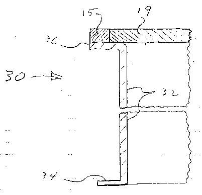
Figure 1 is a partial cross section of one exemplary
embodiment according to the principals of the present
invention.
Figure 2 is a view similar to figure 1 showing the
extension skirt fastened to the skirt of figure 1.
Figure 3 is a partial cross section of a PRIOR ART
--4--

21~0~11
-
manhole installed on small stones and in a layer of concrete.
Figure 4 is a perspective view of a PRIOR-ART circular
manhole of ~he type shown in figure 4.
DETAILED DESCRIPTION OF EXEMPLARY EMBODIMENTS:
With reference to figures 3 and 4, manhole 30,
according to the principles of the present invention,
comprises skirt 32 that terminates in its lower part in an
outwardly extending flange 34. Flange 34 functions to provide
stiffening strength to the skirt 34 to resist deformation
from impact or bending forces that may be applied to the
skirt. In the case of metal skirts, flange 35 is preferably
rolled from the same work piece that forms the skirt, for
example, from 12 gauge steel. In the case of molded plastic,
flange can be form when the entire skirt if molded.
The lateral dimension of flange 34 is selected to
provide suitable stiffening and strength. In one example, the
flange extends one-half inch from the lZ gauge, 36 inch
diameter, steel skirt cylinder profile.
The upper rim of skirt 32 also terminates in an
outwardly projecting lip 36 dimensioned to cooperate with the
top ring 15, welded or bonded to the outer part of lip 36.
The inner part of lip 36 is free to removably support the

- 216021~
_
outer part of cover 19
During installation, flange 34 serves as a foot piece to
prevent skirt 32 from penetrating into the small stone bed or
dirt, thus holding the top ring 15 a true distance above the
concrete supporting surface.
With reference to figure 2, the manhole includes an
extension skirt 40 having a flange 42 extending outwardly
from the bottom thereof. The outer diameter of extension
skirt 40 is sized to enable skirt 40 to telescope into the
bottom of the chamber defined by the inner wall of skirt 32
any suitable distance within the height of skirt 40. Once in
a desired telescoped osition, self drilling and taping
rF5 O r 6~ ~ r ~c,~ ~ ~S ~P /o/7/9y
fasteners 46acan be applied to retain the skirts 32 and 40 is
the desired positions. In this way, the manhole can be
designed to have any height from, for example, 8 inches to 16
inches simply by fastening skirt 40 in place. This can be
done at the installation site to provide greater efficiency
and effectiveness to the installation crew.
It will be understood that various changes and
modifications can be made to the exemplary embodiments herein
disclosed without departing from the spirit and scope of the
--6--

216~211
-
present invention. It should~also be understood that the
figures hereof are not drawn to scale and although metal
parts are shown in the figures, the parts can be formed of
hard plastic or other suitable material if desired..
--7--

Representative Drawing
A single figure which represents the drawing illustrating the invention.
Administrative Status

2024-08-01:As part of the Next Generation Patents (NGP) transition, the Canadian Patents Database (CPD) now contains a more detailed Event History, which replicates the Event Log of our new back-office solution.

Please note that "Inactive:" events refers to events no longer in use in our new back-office solution.

For a clearer understanding of the status of the application/patent presented on this page, the site Disclaimer , as well as the definitions for Patent , Event History , Maintenance Fee  and Payment History  should be consulted.

Event History

Description Date
Inactive: IPC from MCD 2006-03-12
Time Limit for Reversal Expired 2001-10-10
Application Not Reinstated by Deadline 2001-10-10
Deemed Abandoned - Failure to Respond to Maintenance Fee Notice 2000-10-10
Application Published (Open to Public Inspection) 1996-04-12

Abandonment History

Abandonment Date Reason Reinstatement Date
2000-10-10

Maintenance Fee

The last payment was received on 1999-10-08

Note : If the full payment has not been received on or before the date indicated, a further fee may be required which may be one of the following

  • the reinstatement fee;
  • the late payment fee; or
  • additional fee to reverse deemed expiry.

Please refer to the CIPO Patent Fees web page to see all current fee amounts.

Fee History

Fee Type Anniversary Year Due Date Paid Date
MF (application, 2nd anniv.) - standard 02 1997-10-10 1997-10-09
MF (application, 3rd anniv.) - standard 03 1998-10-13 1998-09-21
MF (application, 4th anniv.) - standard 04 1999-10-12 1999-10-08
Owners on Record

Note: Records showing the ownership history in alphabetical order.

Current Owners on Record
UNIVERSAL VALVE CO., INC.
Past Owners on Record
JOSEPH V. MILO
MARTIN C. PETTESCH
Past Owners that do not appear in the "Owners on Record" listing will appear in other documentation within the application.
Documents

To view selected files, please enter reCAPTCHA code :


To view images, click a link in the Document Description column. To download the documents, select one or more checkboxes in the first column and then click the "Download Selected in PDF format (Zip Archive)" or the "Download Selected as Single PDF" button.

List of published and non-published patent-specific documents on the CPD .

If you have any difficulty accessing content, you can call the Client Service Centre at 1-866-997-1936 or send them an e-mail at CIPO Client Service Centre.


Document
Description 
Date
(yyyy-mm-dd) 
Number of pages   Size of Image (KB) 
Abstract 1996-04-12 1 21
Cover Page 1996-06-10 1 15
Claims 1996-04-12 4 82
Description 1996-04-12 7 190
Drawings 1996-04-12 4 84
Representative drawing 1999-08-04 1 9
Reminder of maintenance fee due 1997-06-10 1 109
Courtesy - Abandonment Letter (Maintenance Fee) 2000-11-07 1 183
Courtesy - Office Letter 1995-11-21 3 96
Courtesy - Office Letter 1996-07-26 1 11
PCT Correspondence 1996-05-01 2 79