Sélection de la langue

Search

Sommaire du brevet 2160211 

Énoncé de désistement de responsabilité concernant l'information provenant de tiers

Une partie des informations de ce site Web a été fournie par des sources externes. Le gouvernement du Canada n'assume aucune responsabilité concernant la précision, l'actualité ou la fiabilité des informations fournies par les sources externes. Les utilisateurs qui désirent employer cette information devraient consulter directement la source des informations. Le contenu fourni par les sources externes n'est pas assujetti aux exigences sur les langues officielles, la protection des renseignements personnels et l'accessibilité.

Disponibilité de l'Abrégé et des Revendications

L'apparition de différences dans le texte et l'image des Revendications et de l'Abrégé dépend du moment auquel le document est publié. Les textes des Revendications et de l'Abrégé sont affichés :

  • lorsque la demande peut être examinée par le public;
  • lorsque le brevet est émis (délivrance).
(12) Demande de brevet: (11) CA 2160211
(54) Titre français: REGARD DE VISITE
(54) Titre anglais: MANHOLE
Statut: Réputée abandonnée et au-delà du délai pour le rétablissement - en attente de la réponse à l’avis de communication rejetée
Données bibliographiques
(51) Classification internationale des brevets (CIB):
  • E02D 29/12 (2006.01)
  • E02D 29/14 (2006.01)
(72) Inventeurs :
  • PETTESCH, MARTIN C. (Etats-Unis d'Amérique)
  • MILO, JOSEPH V. (Etats-Unis d'Amérique)
(73) Titulaires :
  • UNIVERSAL VALVE CO., INC.
(71) Demandeurs :
  • UNIVERSAL VALVE CO., INC. (Etats-Unis d'Amérique)
(74) Agent: SWABEY OGILVY RENAULT
(74) Co-agent:
(45) Délivré:
(22) Date de dépôt: 1995-10-10
(41) Mise à la disponibilité du public: 1996-04-12
Licence disponible: S.O.
Cédé au domaine public: S.O.
(25) Langue des documents déposés: Anglais

Traité de coopération en matière de brevets (PCT): Non

(30) Données de priorité de la demande:
Numéro de la demande Pays / territoire Date
08/320,294 (Etats-Unis d'Amérique) 1994-10-11

Abrégés

Abrégé anglais


A manhole embodiment that includes a skirt
having a stiffening flange extending laterally from the
a location near the bottom rim of the skirt to provide
lateral strength and a footing for the manhole and an
outwardly extending lip at the skirt upper rim. The manhole
top ring connects directly to the top of the lip. This
eliminates the need for a separate piece such as the lower
L-shaped ring piece included in conventional manholes.
An optional extension skirt can telescope into the bottom of
the upper skirt that can be held to the upper skirt by
fasteners. The telescoping extension skirt can be height
adjusted in the field so that the over-all height of the
manhole can be adjusted to any desired height, say between 8
and 16 inches.

Revendications

Note : Les revendications sont présentées dans la langue officielle dans laquelle elles ont été soumises.


The embodiments of the invention in which an exclusive property
or privilege is claimed are defined as follows:
Claim 1. A manhole comprising
a skirt forming a partially closed chamber and having
major openings at the top and bottom,
a member connected to the lower portion of said skirt
for providing said skirt lateral strength and stiffness.
Claim 2. A manhole according to claim 1, wherein
said member comprises a laterally extending flange.
Claim 3. A manhole according to claim 2, wherein
said flange extends throughout the horizontal dimension of
the skirt.
Claim 4. A manhole according to claim 2, wherein
said flange is positioned at the bottom of said skirt.
Claim 5. A manhole according to claim 4, wherein
the flange is formed integrally with the skirt as a single
unitary piece.
Claim 6. A manhole according to claim 5, wherein
the flange extends outwardly from the skirt.
-8-

Claim 7. A manhole according to claim 6, wherein
said skirt is cylindrical.
Claim 8. A manhole according to claim 6 further
comprising an extension skirt having a horizontal section
substantially congruent to that of the skirt and dimensioned
to telescope with said skirt and into the space within said
skirt.
Claim 9. A manhole according to claim 8, wherein
joining meqans are provided for connecting the skirt and the
extension skirt to each other at least at two points where
said skirt and said extension skirt overlap.
Claim 10. A manhole according to claim 8, wherein
said extension skirt comprises a laterally extending
extension flange located at the lower portionk of the
extension skirt to provide strength and stiffness to said
extension flange.
Claim 11. A manhole according to claim 10, wherein
extension flange extends throughout the horizontal dimension
of said extension skirt.
-9-

Claim 12. A manhole according to claim 11, wherein
said extension flange is formed from said extension skirt
bottom as a single unitary piece with said extension skirt.
Claim 13. A manhole according to claim 1, wherein
said skirt comprises an outwardly extending lip at its top
portion,
the manhole further comprising a ring having a
predetermined height connected to and supported by the top
surface of the lip, and
a cover removeably supported by said lip within the
periphery of said ring.
Claim 14. A manhole according to claim 13, wherein
said lip is located at the top of the skirt and integrally
formed therewith to form a single unitary piece.
Claim 15. A manhole according to claim 14, wherein
said manhole is circular and is made of metal.
Claim 16. A manhole according to claim 15, wherein
wherein said skirt is made from sheet steel and said lip is
rolled to extend horizontally from the top of the skirt.
-10-

Claim 17. A manhole according to claim 15, wherein
said member comprises a flange, said flange having been
rolled to extend outwardly at the botom of said skirt.
-11-

Description

Note : Les descriptions sont présentées dans la langue officielle dans laquelle elles ont été soumises.

2~602I ~
UNIV - 9
TITLE: IMPROVED MANHOLE
BACXGROUND:
The present invention relates to manholes and more
specifically to new manhole designs that give rise to
stronger and less costly manholes compared-to conventional
manholes.
The art of manhole design is about one century old.
Today, manholes come in a vast variety of shapes, sizes, and
materials and serve a great many purposes. A manhole
comprises three basic parts, namely, a closed skirt that at
least partially embeds in the ground or concrete surface
layer, a closed ring connected to the top of the skirt and a
lid or cover that removably cooperates and permits access to
the interior of the chamber defined by the skirt.
With reference to figures 3 and 4, a typical
conventional, circular manhole 10 is shown that comprises a

216021~
-
cylindrical skirt 12, a closed cast metal ring 14, and a
removable circular metal lid ~6. Skirt 12 is commonly form
from sheet steel, cut and welded at a seam to form the
cylinder. Ring 14 is typically cast in two circular parts,
closed L-shaped lower ring 17 and cylindrical top ring 18.
Ring 17 is welded to the top of skirt 12 and ring 18 is
welded to the top of ring 17, generally as shown. Cover 16
rests on ring 17 when is the closed position.
In practice, manholes are fabricated at a works location
and delivered with the skirt 12 and ring welded in place.
Installation includes usually preparing a bed of small stones
20 below ground surface, placing the manhole with the bottom
rim of skirt 12 resting on stones 20 so that the top of ring
18 defines a predetermined ground plane or surface above
stones 20. Concrete 22 is then poured on to stones 20 to a
predetermined depth, such as a standard 8 or 16 inches.
Conventional manholes create a number of problems in the
field. For example, the skirts of manholes greater than 24
inches in diameter provide insufficient lateral streng~h
giving rise to bending or other or other deformation of the
skirt during handling. For example, manholes are often placed
on their sides during delivery or installation, thereby
--2--

2160211
-
resting on one point of ring 14 and one point of the bottom
of skirt 12. The heavy weight~of the parts thus deform skirt
12 causing problems with installation of the manhole itself
and sometimes the placement of equipment to be housed in the
chamber.
In addition, the bottom rim of skirt 12 tends to
penetrate the bed of small stones 20, thus reducing the
vertical distance available for the thickness of concrete 22.
This sometimes leads to the concrete depth being below
required specifications which is very costly to correct.
Also, the conventional fabrication of the rings 17 and
18 on the top of skirt 12 requires many process steps and
welds or connections, thus increasing the manufacturing costs
of the assembly.
SUMMARY OF EXEMPLARY EMBODIMENTS OF THE INVENTION
An exemplary manhole embodiment according to the
principles of the present invention includes a skirt
having a stiffening flange extending laterally from the
a location near the bottom rim of the skirt to provide
lateral strength and a footing for the manhole.
Another aspect of the invention is to provide an
--3--

2160211
outwardly extending integral lip at the skirt upper rim and
connect the top ring directly to the top of the lip. This
eliminates the need for a separate piece such as the lower
ring 17 shown in figure 3.
A still further aspect of the present invention provides
a manhole having a standard depth, such as 8 inches, and an
extension skirt that can telescope into the bottom of the
skirt and that can be held to the skirt by fasteners. The
telescoping extension skirt can be height adjusted so that
the over-all height of the manhole can be adjusted to any
desired height, say between 8 and 16 inches.
Other and further benefits and advantages will become
apparent with the following detailed description when taken
in view of the appended drawings, in which:
DRAWINGS:
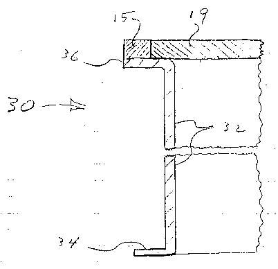
Figure 1 is a partial cross section of one exemplary
embodiment according to the principals of the present
invention.
Figure 2 is a view similar to figure 1 showing the
extension skirt fastened to the skirt of figure 1.
Figure 3 is a partial cross section of a PRIOR ART
--4--

21~0~11
-
manhole installed on small stones and in a layer of concrete.
Figure 4 is a perspective view of a PRIOR-ART circular
manhole of ~he type shown in figure 4.
DETAILED DESCRIPTION OF EXEMPLARY EMBODIMENTS:
With reference to figures 3 and 4, manhole 30,
according to the principles of the present invention,
comprises skirt 32 that terminates in its lower part in an
outwardly extending flange 34. Flange 34 functions to provide
stiffening strength to the skirt 34 to resist deformation
from impact or bending forces that may be applied to the
skirt. In the case of metal skirts, flange 35 is preferably
rolled from the same work piece that forms the skirt, for
example, from 12 gauge steel. In the case of molded plastic,
flange can be form when the entire skirt if molded.
The lateral dimension of flange 34 is selected to
provide suitable stiffening and strength. In one example, the
flange extends one-half inch from the lZ gauge, 36 inch
diameter, steel skirt cylinder profile.
The upper rim of skirt 32 also terminates in an
outwardly projecting lip 36 dimensioned to cooperate with the
top ring 15, welded or bonded to the outer part of lip 36.
The inner part of lip 36 is free to removably support the

- 216021~
_
outer part of cover 19
During installation, flange 34 serves as a foot piece to
prevent skirt 32 from penetrating into the small stone bed or
dirt, thus holding the top ring 15 a true distance above the
concrete supporting surface.
With reference to figure 2, the manhole includes an
extension skirt 40 having a flange 42 extending outwardly
from the bottom thereof. The outer diameter of extension
skirt 40 is sized to enable skirt 40 to telescope into the
bottom of the chamber defined by the inner wall of skirt 32
any suitable distance within the height of skirt 40. Once in
a desired telescoped osition, self drilling and taping
rF5 O r 6~ ~ r ~c,~ ~ ~S ~P /o/7/9y
fasteners 46acan be applied to retain the skirts 32 and 40 is
the desired positions. In this way, the manhole can be
designed to have any height from, for example, 8 inches to 16
inches simply by fastening skirt 40 in place. This can be
done at the installation site to provide greater efficiency
and effectiveness to the installation crew.
It will be understood that various changes and
modifications can be made to the exemplary embodiments herein
disclosed without departing from the spirit and scope of the
--6--

216~211
-
present invention. It should~also be understood that the
figures hereof are not drawn to scale and although metal
parts are shown in the figures, the parts can be formed of
hard plastic or other suitable material if desired..
--7--

Dessin représentatif
Une figure unique qui représente un dessin illustrant l'invention.
États administratifs

2024-08-01 : Dans le cadre de la transition vers les Brevets de nouvelle génération (BNG), la base de données sur les brevets canadiens (BDBC) contient désormais un Historique d'événement plus détaillé, qui reproduit le Journal des événements de notre nouvelle solution interne.

Veuillez noter que les événements débutant par « Inactive : » se réfèrent à des événements qui ne sont plus utilisés dans notre nouvelle solution interne.

Pour une meilleure compréhension de l'état de la demande ou brevet qui figure sur cette page, la rubrique Mise en garde , et les descriptions de Brevet , Historique d'événement , Taxes périodiques et Historique des paiements devraient être consultées.

Historique d'événement

Description Date
Inactive : CIB de MCD 2006-03-12
Le délai pour l'annulation est expiré 2001-10-10
Demande non rétablie avant l'échéance 2001-10-10
Réputée abandonnée - omission de répondre à un avis sur les taxes pour le maintien en état 2000-10-10
Demande publiée (accessible au public) 1996-04-12

Historique d'abandonnement

Date d'abandonnement Raison Date de rétablissement
2000-10-10

Taxes périodiques

Le dernier paiement a été reçu le 1999-10-08

Avis : Si le paiement en totalité n'a pas été reçu au plus tard à la date indiquée, une taxe supplémentaire peut être imposée, soit une des taxes suivantes :

  • taxe de rétablissement ;
  • taxe pour paiement en souffrance ; ou
  • taxe additionnelle pour le renversement d'une péremption réputée.

Veuillez vous référer à la page web des taxes sur les brevets de l'OPIC pour voir tous les montants actuels des taxes.

Historique des taxes

Type de taxes Anniversaire Échéance Date payée
TM (demande, 2e anniv.) - générale 02 1997-10-10 1997-10-09
TM (demande, 3e anniv.) - générale 03 1998-10-13 1998-09-21
TM (demande, 4e anniv.) - générale 04 1999-10-12 1999-10-08
Titulaires au dossier

Les titulaires actuels et antérieures au dossier sont affichés en ordre alphabétique.

Titulaires actuels au dossier
UNIVERSAL VALVE CO., INC.
Titulaires antérieures au dossier
JOSEPH V. MILO
MARTIN C. PETTESCH
Les propriétaires antérieurs qui ne figurent pas dans la liste des « Propriétaires au dossier » apparaîtront dans d'autres documents au dossier.
Documents

Pour visionner les fichiers sélectionnés, entrer le code reCAPTCHA :


Pour visualiser une image, cliquer sur un lien dans la colonne description du document. Pour télécharger l'image (les images), cliquer l'une ou plusieurs cases à cocher dans la première colonne et ensuite cliquer sur le bouton "Télécharger sélection en format PDF (archive Zip)" ou le bouton "Télécharger sélection (en un fichier PDF fusionné)".

Liste des documents de brevet publiés et non publiés sur la BDBC .

Si vous avez des difficultés à accéder au contenu, veuillez communiquer avec le Centre de services à la clientèle au 1-866-997-1936, ou envoyer un courriel au Centre de service à la clientèle de l'OPIC.


Description du
Document 
Date
(aaaa-mm-jj) 
Nombre de pages   Taille de l'image (Ko) 
Abrégé 1996-04-12 1 21
Page couverture 1996-06-10 1 15
Revendications 1996-04-12 4 82
Description 1996-04-12 7 190
Dessins 1996-04-12 4 84
Dessin représentatif 1999-08-04 1 9
Rappel de taxe de maintien due 1997-06-10 1 109
Courtoisie - Lettre d'abandon (taxe de maintien en état) 2000-11-07 1 183
Courtoisie - Lettre du bureau 1995-11-21 3 96
Courtoisie - Lettre du bureau 1996-07-26 1 11
Correspondance reliée au PCT 1996-05-01 2 79