Note: Descriptions are shown in the official language in which they were submitted.
- 1 -
AN ELECTRIC VACUUM CLEANER
The present invention relates to an electric
vacuum cleaner and more specifically relates to an
improved device for attaching and detaching of a dust
collecting bag for the vacuum cleaner as well as to an
improved storing device for storing attached suction
nozzles for the vacuum cleaner into the appliance body.
Various kinds of improved electric vacuum
cleaners have been proposed. Of these, there are types
of electric vacuum cleaners which have a detachable dust
collecting bag in a dust collecting chamber inside the
appliance housing so as to allow the dust collecting bag
to be replaced. Two kinds of structures are known as to
the cleaners of this type: one of which has a lidding
member which is attached to the appliance housing and can
be opened and closed for the dust collecting bag to be
replaced. In the other structure, the dust collecting
bag is replaced by separating the appliance housing.
,._. ~ r 1
- 2 -
Figs.l and 2 show an electric vacuum cleaner having a
lidding member for a dust collecting bag to be replaced.
In Fig.l, an appliance housing 41 is so arranged as to
divide the inside into two parts, that is, a dust collecting
chamber 42 and a motor room 44 holding an electric fan 43.
A connecting port 45 for connecting a connecting hose (not
shown) therewith is formed in the appliance housing 41 so
as to be projected into the side of dust collecting chamber
42. A dust collecting bag 47 with an attachment frame 46
is attached to the connecting port 45 on the side of the
dust collecting chamber 42 while a catching device 48 for
fixing the dust collecting bag 47 is provided for the dust
collecting chamber 42 in the vicinity of the connecting port
45. The housing 41 further has a lidding member 49 for
opening and closing an opening formed on the upper part of
the dust collecting chamber 42.
Particularly, as shown in Fig.2, the width E of the
lower part of the dust collecting chamber 42 is
approximately equal to the width of the dust collecting bag
47 when it is inflated to the maximum. The width F of the
upper part of the dust collecting chamber 42 is designed to
be smaller than the width E of the lower part of the dust
collecting chamber 42.
When the dust collecting bag 47 is to be replaced in
the above electric vacuum cleaner having the dust collecting
ry~ . 1
- 3 -
bag 47 replaced by opening the lidding member 49, the dust
collecting bag 47 is replaced by opening the lidding member
49 for covering the opening on the top of the dust
collecting chamber 42; releasing tre engagement between the
attachment frame 46 and the catching device 48 by fingering
the catching device 48 in a disengaging direction; detaching
the dust collecting bag 47 through the top opening of the
dust collecting chamber 42; and attaching a new dust
collecting bag 47.
As disclosed in Japanese Utility Model Publication Sho
64 No.2,680, an electric vacuum cleaner in which a dust
collecting bag is replaced by separating the appliance
housing is conf figured as shown in Figs . 3 and 4 . In Figs . 3
and 4, the electric vacuum cleaner has an appliance housing
51 which is formed of and can be separated into a dust
collecting casing 53 having a dust collecting chamber 52 and
a motor casing 55 having an electric fan 54 therein. A
connecting port 56 for connecting a connecting hose (not
shown ) is formed in the dust collecting casing 53 on the
opposite side of an opening 53a of the dust collecting
casing 53 which is joined to the motor casing 55, in such
a manner that the connecting port 56 is projected into the
dust collecting chamber 52. A dust collecting bag 58 having
an attachment frame 57 is attached to the connecting port
56 on the side of the dust collecting chamber 52. The dust
- 4 -
collecting chamber 52 further has a frame member 59 which
is detached together with the dust collecting bag 58 from
the dust collecting casing 53 through the opening 53a
thereof.
The aforementioned frame member 59 is integrally formed
of a catching device 60 for holding the dust collecting bag
58 by catching the attachment frame 57 and a seal packing
61 for forming a hermetic joint between the dust collecting
casing 53 and the motor casing 55.
In the electric vacuum cleaner in which the dust
collecting bag 58 is replaced by separating the appliance
housing 51, the dust collecting bag 58 is replaced by
separating the appliance housing 51 into the dust collecting
casing 53 and the motor casing 55; detaching the dust
collecting bag 58 together with the frame member 59 through
the opening 53a of the dust collecting casing 53; releasing
the engagement of the attachment frame 57 by fingering the
catching device 60 in a disengaging direction; and replacing
the old dust collecting bag 58 with a new one.
In the electric vacuum cleaner with the lidding member
49 being opened and closed when the dust collecting bag 47
is replaced, the width F of the upper part of the dust
collecting chamber 42 is smaller than the width E of the
lower part of the dust collecting chamber 42, as mentioned
above. Therefore, when the dust collecting bag 47 totally
.'
.>
- 5 -
expanded inside the lower part of the dust collecting
chamber 42 is to be detached through the upper opening of
the dust collecting chamber 42, the dust collecting bag 47
is caught by the inner face of the dust collecting casing
defining the upper part of the dust collecting chamber 42,
thus making it difficult to take the dust collecting bag 47
out.
On the other hand, in the electric vacuum cleaner in
which the dust collecting bag 58 is replaced by decomposing
the appliance housing 51, since the dust collecting bag 58
is detached together with the frame member 59 from the dust
collecting casing 53 through the opening 53a thereof, the
dust collecting bag 58 must be detached from the frame
member 59 by releasing the engagement of the catching device
60 with the attachment frame 57. That is, the replacement
requires extra handling time and labor.
Meanwhile, there are electric vacuum cleaners which
incorporate an electric fan in a main body thereof and have
a depressed portion for storing.accessory~suction nozzles
therein. A typical electric vacuum cleaner of this kind has
been disclosed in Japanese Utility Model Publication Hei 3
No.17,816 and will be described hereinafter with reference
to Fig. S. This cleaner comprises: a cleaner body 121 with
an electric fan (not shown) incorporated therein; a pair of
wheels 122 on both sides of the cleaner body 121; a storage
.,,
3
- 6 -
125 disposed on top of the cleaner body 121 for storing
accessory suction nozzles such as a brush-equipped suction
nozzle 123 having bristles and a gap-cleaning suction nozzle
124 having an elongated nozzle portion for cleaning gaps; a
depressed portion corresponding to the shapes of the brush-
equipped suction nozzle 123 and the gap-cleaning suction
nozzle 124; a lid 126 disposed on the top of cleaner body
121 for opening and closing the storage 125; a connecting
port 127 disposed on the front side of the cleaner body 121
for connecting an extension hose (not shown); and an
extension tube (not shown) which is connected to the
extension hose at one end and jointed at the opposite end
with one of the aforementioned brush-equipped suction nozzle
123 or gap-cleaning suction nozzle 124.
Another conventional electric vacuum cleaner will be
described referring to Fig.6: This cleaner comprises: a
cleaner body 131 with an electric fan (not shown)
incorporated therein; a pair of wheels 132 on both sides of
the cleaner body 131; a pivoting handle 133 disposed on the
top of the cleaner body 131; a depressed storage portion 135
disposed in the rear lower portion of the cleaner body 131
for storing a gap-cleaning suction nozzle 134 fitted
therein.
Another example of a conventional electric vacuum
cleaner is found in Japanese Utility Model Application
;z
' .r~,
- 7 _
Laid-Open Sho 61 No.67,646. This electric vacuum cleaner
is formed with a pair of U-shaped cutout portions on the
rear upper part of the appliance housing and has a storage
for suction nozzles below the cutout portions so that shelf-
cleaning and gap-cleaning suction nozzles are fitted in
respective U-shaped cutout portions.
In the case of the electric vacuum cleaner shown in
Fig.5, since two depressed holding portions must be provided
on the top surface of the cleaner body in order to store the
brush-equipped and gap-cleaning suction nozzles,
respectively, the appliance body tends to be bulky and
heavy, requiring a large storage space for keeping the
appliance and making it difficult to use or deteriorating
its handling performance. Further, the lid for opening and
closing the storage tends to break.
In the case of the electric vacuum cleaner shown in
Fig.6, the depressed storage can only hold the gap-cleaning
suction nozzle fitted therein. If there are a plurality of
accessory suction nozzles, a plurality of depressed storage
portions should be formed in conformity with the number of
the accessory suction nozzles, like the former
configuration. Therefore, the appliance body again tends
to be bulky and heavy, requiring a large storage space
for keeping the appliance and making it difficult to use or
deteriorating its handling performance.
_ g _
In the aforementioned configuration disclosed in
Japanese Utility Model Application Laid-Open Sho 61
No.67,646, since the shelf-cleaning suction nozzle and the
gap-cleaning suction nozzle are fitted into respective
cutout portions and stored separately, two storage spaces
corresponding to the shelf-cleaning and gap-cleaning suction
nozzles are required, whereby it is impossible to make the
storage room compact.
The electric vacuum cleaner of the present invention
has been invented to improve upon the deficiencies
of the aforementioned prior art and it is therefore
an object of the present invention to provide an
electric vacuum cleaner wherein when a dust collecting bag
is replaced, the dust collecting bag will not be caught
between interior walls of a dust collecting casing and the
dust collecting bag can easily be replaced by taking the
dust collecting bag out in a single-step operation without
requiring any troublesome handling for the replacement.
It is another object of the present invention to
provide a compact electric vacuum cleaner by constructing
suction nozzles and a storage portion therefor in such a
manner that storage of the suction nozzles is done by
integrally fitting the nozzle portion of a gap-cleaning
suction nozzle into a brush-equipped suction nozzle and
~'~r
ra.
r
....
_ g _
fitting the integrated suction nozzles to a depressed
storage portion, to thereby reduce the storage space
required for the suction nozzles.
The present invention has been achieved to attain the
above objects, and in accordance with a first aspect of the
invention, an electric vacuum cleaner having an appliance
body composed of a motor casing portion having an electric
fan therein and a dust collecting casing portion having a
dust collecting chamber, comprises: an appliance housing;
a catching means disposed in the appliance housing for
detachably catching a dust collecting bag collecting dust,
dirt and the like; and a releasing means allowing a
releasing operation from the outside to free the engaged
state of the dust collecting bag in the catching means.
In accordance with a second aspect of the invention,
an electric vacuum cleaner having an appliance body composed
of a motor casing portion having an electric fan therein and
a dust collecting casing portion having a dust collecting
chamber, comprises: an appliance housing composed of and
separated into a dust collecting casing having a dust
collecting chamber and a motor casing having an electric fan
therein; and a catching means disposed in the dust
collecting chamber for detachably catching a dust collecting
bag for collecting dust, dirt and the like, and is
- to - ~ ,
constructed so that the dust collecting bag is adapted to
be removed through an opening of the dust collecting casing
where the dust collecting casing is to be j oined to the
motor casing; and the dust collecting casing is constructed
so that the section of the dust collecting casing becomes
gradually greater in width toward the opening of the dust
collecting casing.
In the above configuration, any of the following
features is effective: the electric vacuum cleaner further
includes an air-sealing means for hermetically sealing the
joining face between the dust collecting casing and the
motor casing and a groove portion for holding the air-
sealing means so as not to project inward of the inner
surface of the dust collecting casing; the electric vacuum
cleaner further includes a preventing means for preventing
the releasing means from effecting the releasing operation
when the dust collecting casing is being joined .to the
motor casing; and the electric vacuum cleaner further
includes an operation-disabling means for disabling the
operation of the cleaner when the dust collecting bag is not
engaged in the catching means.
In accordance with another aspect of the present
invention, an electric vacuum cleaner having an appliance
body composed of a motor casing portion having an electric
fan therein and a dust collecting casing portion having a
F
- 11 -
dust collecting chamber, comprises: two types of accessory
suction nozzles including a brush-equipped suction nozzle
with bristles and a gap-cleaning suction nozzle having an
elongated nozzle portion for cleaning gaps; and a depressed
storage portion for fitting the accessory suction nozzles
in the appliance body, and the depressed storage
portion is constructed so that the suction nozzles
can be attached to the depressed storage portion by
inserting the nozzle portion of the gap-cleaning suction
nozzle into the brush-equipped suction nozzle and fitting
the integrally fitted part consisting of the brush-equipped
suction nozzle and the gap-cleaning suction nozzle, into the
depressed storage portion.
In the above configuration, any of the following
features is effective: the fitting portion provided for the
brush-equipped suction nozzle to be fitted to the depressed
storage portion and the fitting portion provided for the
gap-cleaning suction nozzle to be fitted to the depressed
storage portion have an identical outside diameter, so that
any one of the brush-equipped suction nozzle and gap-
cleaning suction nozzle can be fitted and stored into the
depressed storage portion; and a front end of the nozzle
portion of the gap-cleaning suction nozzle is formed to be
inclined; and a length from the frontmost position of the
nozzle portion to the boundary of the fitting portion is
-'
- 12 -
designed not to abut the interior surface of the brush-
equipped suction nozzle when the nozzle portion is inserted
into the brush-equipped suction nozzle.
In accordance with still another aspect of the present
invention, an electric vacuum cleaner having an appliance
body composed of a motor casing portion having an electric
fan therein and a dust collecting casing portion having a
dust collecting chamber, comprises: an appliance housing
composed of and separated into a dust collecting casing
having a dust collecting chamber and a motor casing having
an electric fan therein; a catching means disposed in the
dust collecting chamber for detachably catching a dust
collecting bag for collecting dust, dirt and the like; a
releasing means allowing a releasing operation from the
outside to free the engaged state of the dust collecting bag
in the catching means; two types of accessory suction nozzles
including a brush-equipped suction nozzle with bristles and
a gap-cleaning suction nozzle having an elongated nozzle
portion for cleaning gaps; and a depressed storage portion
for fitting the accessory suction nozzles in the appliance
body, and is constructed such that the dust collecting bag
can be removed from an opening where the dust collecting
casing is to be joined to the motor casing, by separating
the appliance housing into the collecting casing and the
electric casing and effecting the releasing operation by the
- 13 -
releasing means; and the depressed storage portion is
constructed so that the suction nozzles can be attached
to the depressed storage portion by inserting the nozzle
portion of the gap-cleaning suction nozzle into the
brush-equipped suction nozzle and fitting the integrally
fitted part consisting of the brush-equipped suction
nozzle and the gap-cleaning suction nozzle, into the
depressed storage portion.
In the above configuration, any of the following
features is effective: the dust collecting casing
becomes gradually greater in width toward the opening of
the dust collecting casing; the electric vacuum cleaner
further incudes an air-sealing means for hermetically
sealing the joining face between the dust collecting
casing and the motor casing; and a groove portion for
holding the air-sealing means so as not to project
inward of the inner surface of the dust collecting
casing; the electric vacuum cleaner includes a preventing
means for preventing the releasing means from effecting
the releasing operation when the dust collecting casing
is being joined to the motor casing; an operation-
disabling means for disabling the operation of the
cleaner when the dust collecting bag is not engaged
in the catching means; the fitting portion provided for
the brush-equipped suction nozzle to be fitted to the
- 14 -
depressed storage portion and the fitting portion provided
for the gap-cleaning suction nozzle to be fitted to the
depressed storage portion have an identical outside
diameter, so that any one of the brush-equipped suction
nozzle and gap-cleaning suction nozzle can be fitted and
stored into the depressed storage portion; and a front end
of the nozzle portion of the gap-cleaning suction nozzle is
formed to be inclined, and a length from the frontmost
position of the nozzle portion to the boundary to the
fitting portion is designed not to abut the interior
surface of the brush-equipped suction nozzle when the nozzle
portion is inserted into the brush-equipped suction nozzle.
Since the electric vacuum cleaner of the invention is
thus constructed, the replacement of the dust collecting bag
can be done by operating the releasing means from the
outside of the appliance housing to release the engaged
state of the dust collecting bag in the catching means. In
consequence, it is possible for the operator to remove the
dust collecting bag easily in a single-step operation
without requiring any troublesome handling for the
replacement.
Since, in the present invention, the dust collecting
casing is formed so that the section of the dust collecting
casing becomes gradually greater in width toward the opening
~~.so~~o
- 15 -
of the casing; when the appliance housing is separated into
the dust collecting casing and the motor casing thereafter
the releasing lever is freed with the opening of the dust
collecting casing down, it is possible to take the dust
collecting bag out by allowing the bag not to be caught
between the inner walls of the dust collecting casing but
to slide down smoothly.
Further, in the above configuration of the present
invention, since a groove portion is provided so as not to
allow the air-sealing means to project out from the level
of the inner wall of the dust collecting casing, the dust
collecting bag can be removed smoothly without being caught
by the air-sealing means when the dust collecting bag is
taken out by sliding it down. Further, since the air-
sealing means is provided inside the peripheral wall of the
dust collecting casing, it is possible to form a perfectly
hermetic state at the joining surface between the dust
collecting casing and the motor casing, without degrading
the outside appearance of the appliance housing.
Moreover, in the above configuration of the present
invention, since the blocking means prevents the releasing
means from effecting disengagement of the dust collecting
bag while the dust collecting casing and the motor casing
are being joined, the dust collecting bag will not get out
of place unexpectedly during cleaning, so that it is
,.~ - 16 - ~ ~ ~ ~ ~r
possible to prevent the appliance from breaking due to the
pollution of dust and dirt inside the appliance which would
be caused by unexpected disengagement of the dust collecting
bag.
In addition, in the above configuration, the operation
of the cleaner is disabled by the operation-disabling means
when the dust collecting bag is not engaged by the catching
means, to thereby warn the operator of the failure to attach
the dust collecting bag. In consequence, it is possible to
prevent the appliance from breaking due to the pollution of
dust and dirt inside the appliance which would be caused by
not attaching the dust collecting bag.
On the other hand, since in the electric vacuum
cleaner of the present invention, the storage of the suction
nozzles is done by integrally fitting the nozzle portion of
the gap-cleaning suction nozzle into the brush-equipped
suction nozzle and fitting the integrated suction nozzles
into the depressed storage portion, it is possible to reduce
the size of the storage space for the suction nozzles. In
consequence, the cleaner body itself can also be made
compact.
In the above electric vacuum cleaner, since the
fitting portion of the brush-equipped suction nozzle and the
fitting portion of the gap-cleaning suction nozzle have an
identical outside diameter; when the brush-equipped suction
nozzle is used, it is possible to fit and store the gap-
cleaning suction nozzle alone in the depressed storage
portion. It is also possible to fit and store the brush-
equipped suction nozzle alone in the depressed portion when
the gap-cleaning suction nozzle is in use.
,a,
o u..;
- 17 -
In the above electric vacuum cleaner, since the length
of the front part of the nozzle portion of the gap-cleaning
suction nozzle is designed not to abut the interior surface
of the brush-equipped suction nozzle; when the nozzle portion
of the gap-cleaning suction nozzle is inserted into the
brush-equipped suction nozzle, it is possible to insert the
gap-cleaning suction nozzle into the brush-equipped suction
nozzle, with it rotated in any direction along its
longitudinal axis.
These and other objects of the present application
will become more readily apparent from the detailed
description given hereinafter. However, it should be
understood that the detailed description and specific
examples, while indicating preferred embodiments of the
invention, are given by way of illustration only, since
various changes and modifications within the spirit and scope
of the invention will become apparent to those skilled in the
art from this detailed description.
BRIEF DESCRIPTION OF THE DRAWINGS
Fig.l is a sectional side view showing essential
components of a conventional electric vacuum cleaner in which
a lidding member is opened and closed when a dust collecting
bag is replaced;
Fig.2 is a sectional view showing essential components
(taken on 80-81 in Fig. l);
Fig.3 is a sectional side view showing essential
components of a conventional electric vacuum cleaner in
__ 2~~.~02~?9
- 18 -
which an appliance housing is separated when a dust
collecting bag is replaced;
Fig.4 is a sectional side view showing essential
components in which a dust collecting bag is taken out from
a dust collecting casing shown in Fig.3;
Fig.S is a perspective view showing an example of a
conventional electric vacuum cleaner;
Fig.6 is a perspective view showing another example of
a conventional electric vacuum cleaner;
Fig.7 is a sectional side view showing essential
components of a first embodiment of an electric vacuum
cleaner of the present invention;
Fig.8 is an enlarged sectional side view showing
essential components on the dust collecting casing side of
Fig.7;
Fig.9 is a sectional side view showing essential
components of a second embodiment of an electric vacuum
cleaner of the present invention;
Fig.lO is a sectional side view showing essential
components of a third embodiment of an electric vacuum
cleaner of the present invention;
Fig.ll is an enlarged view showing components indicated
by a circle B in Fig.lO;
Fig.l2 is an enlarged view showing components indicated
by a circle C in Fig.lO;
- 19 -
Fig.l3 is an enlarged view showing a state of
components indicated by the circle B in Fig.lO where a dust
collecting bag is taken out from an appliance housing
decomposed;
Fig.l4 is an enlarged view showing a state of
components indicated by the circle C in Fig.lO where a dust
collecting bag is taken out from an appliance housing
decomposed;
Fig. l5 is a sectional side view showing essential
components of a fourth embodiment of an electric vacuum
cleaner of the present invention;
Fig. l6 is an enlarged view showing components indicated
by a circle D in Fig. l5;
Fig.l7 is an enlarged view showing a state of
components indicated by the circle D in Fig. l5 where a dust
collecting bag is taken out from an appliance housing
decomposed;
Fig.l8 is a perspective view showing a fifth embodiment
of an electric vacuum cleaner of the present invention;
Fig. l9 is a side view of Fig. l8;
Fig.20 is a side view showing a state where a gap-
cleaning suction nozzle is inserted into a brush-equipped
suction nozzle in the electric vacuum cleaner in accordance
with the fifth embodiment of the present invention;
Fig.21 is a sectional view of Fig.20;
- 20 -
Fig.22 is a partial plan view of Fig.20;
Fig.23 is a sectional view showing a part of a
depressed storage portion in the electric vacuum cleaner in
accordance with the fifth embodiment of the present
invention;
Fig.24 is a sectional view showing another part of a
depressed storage portion in the electric vacuum cleaner
in accordance with the fifth embodiment of the present
invention;
Fig.25 is a backside view showing a state where both
brush-equipped and gap-cleaning suction nozzles are fitted
in the depressed storage portion in the electric vacuum
cleaner in accordance with the fifth embodiment of the
present invention;
Fig.26 is a sectional view of the depressed storage
portion shown in Fig.25;
Fig.27 is a backside view showing a state where only
the gap-cleaning suction nozzle is fitted in the depressed
storage portion in the electric vacuum cleaner in accordance
the fifth embodiment of the present invention;
Fig.28 is a sectional view of the depressed storage
portion shown in Fig.27;
Fig.29 is a backside view showing a state where only
the brush-equipped suction nozzle is fitted in the depressed
storage portion in the electric vacuum cleaner in accordance
",- - 21 -
with the fifth embodiment of the present invention;
Fig.30 is a sectional view of the depressed storage
portion shown in Fig.29;
Fig.31 is a plan view partially showing another example
of a state where the gap-cleaning suction nozzle is inserted
into the brush-equipped suction nozzle in the electric
vacuum cleaner in accordance with the fifth embodiment of
the present invention; and
Fig.32 is a sectional side view showing essential
components of an electric vacuum cleaner in accordance with
a sixth embodiment of the present invention.
DESCRIPTION OF THE PREFERRED EMBODIMENTS
Embodiments of electric vacuum cleaners of the present
invention will hereinafter be described in detail, with
reference to Figs.7 through 17.
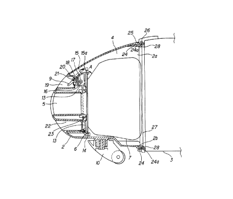
Figs.7 and 8 show an electric vacuum cleaner in
accordance with a first embodiment of the present invention.
In Fig.7, an appliance housing 1 is formed of two separable
components, that is, a dust collecting casing 2 and a motor
casing 3. The dust collecting casing 2 is constructed so
that the section of the casing 2 becomes gradually greater
in width toward an opening 2a or the distal end of the
casing 2 where the dust collecting casing 2 is to be joined
to the motor casing 3.
- 22 -
The dust collecting casing 2 has a dust collecting
chamber 4 where dust and dirt are collected therein. A
connecting port 5 for connecting an unillustrated connecting
hose is formed on the dust collecting case 2 on the opposite
surface to the opening 2a in such a manner that the
connecting port 5 is projected to the side of the dust
collecting chamber 4. A dust collecting bag 7 having a
rectangular (inclusive of square) attachment frame 6 is
attached to the connecting port 5 on the side of the dust
collecting chamber 4. A receiving portion 8 for receiving
the attachment frame 6 is provided in the dust collecting
chamber 4 in the vicinity of the connecting port 5, in order
to fix the dust collecting bag 7. A releasing lever 9 for
allowing an operator to release the engagement of the
receiving portion 8 with the dust collecting bag 7 from the
outside is integrally formed with the receiving portion 8.
Provided beneath the dust collecting casing 2 is a roller
portion 10 which is able to swivel its roller in conformity
with the moving direction of the cleaner.
The aforementioned motor casing 3 incorporates an
electric fan 11 therein for generating suction forces
drawing dust and dirt etc., and is provided with a pair of
wheels 12 on both sides in the lower part thereof.
Fig.B is an enlarged sectional side view showing the
side of the dust collecting case 2. Referring to the
- 23 -
figure, the dust collecting casing 2 will be described in
detail. That is, the aforementioned receiving portion 8 is
composed of: upper and lower dust collector attachment
plates 13 disposed inside the dust collecting chamber 4 in
the vicinity of the connecting port 5; a claw-shaped piece 14
formed in the lower dust collector attachment plate 13 for
receiving the lower side of the attachment frame 6; and a
clamp 15 with a claw 15a disposed in the upper dust collector
attachment plate 13 for receiving the upper side of the
attachment frame 6 to fix the dust collecting bag 7.
A pair of shafts 16 are formed opposed to each other
on the clamp 15 while a pair of supporting holes 17 are
formed on the upper dust collector attachment plate 13,
opposed to each other for supporting the shafts 16 to allow
the clamp 15 to rotate in the directions of arrows A in Fig.
8. Provided between the dust collector attachment plate 13
and the clamp 15 is a spring 18 which urges the clamp 15
toward the clamping direction (the direction from a position
of the clamp 15 indicated by imaginary lines to the position
indicated by solid lines).
A U-shaped (in the horizontal direction) depressed
portion 19 recessed in parallel with the connecting port 5
toward the dust collecting chamber 4 is formed in the dust
24
collecting casing 2 in a position over the connecting port
5. A via-hole 20 is formed in the depressed portion 19 to
allow the releasing lever 9 integrally formed with the
clamp 15 to come out therethrough while a clamp sealing
21 is provided on the periphery of the via-hole 20 in
order to seal the gap between the releasing lever 9 and
the via-hole 20.
Further, another U-shaped (in the horizontal direction)
handgrip 22 recessed in parallel with the connecting port
5 toward the dust collecting chamber 4 is formed in the dust
collecting casing 2 in a position under the connecting port
5. A seal packing 23 is provided in the periphery of the
connecting port 5 on the side of the dust collecting chamber
4 in order to seal the gap among the connecting port 5, the
dust collector attachment plate 13 and the attachment frame
6 to ensure hermetic confinement.
Further, the dust collecting casing 2 has a stepped
portion 24 enclosing an opening rim 2b of the dust
collecting casing 2 from the outside. A groove 25 is cut
out on the outside surface of an opening rim 24a on the
upper part of the stepped portion 24 while a fitting
projection 26 for mating the groove 25 is disposed on the
outside rim on the upper part of the motor casing 3.
Further, a proj ected j oining portion 27 for making a j oint
between the dust collecting casing 2 and the motor casing
- 25 -
3 is formed on the side of the motor casing 3.
A seal packing 28 for hermetically sealing the j oining
face between the dust collecting casing 2 and the motor
casing 3 is .provided so as not to project inward of the
inner face of the opening rim 2b of the dust collecting
casing 2 on the whole circumference of the stepped portion
24. This seal packing 28 is configurated so as to be nipped
between the opening rim 2b of the dust collecting casing 2
and the joining portion 27 of the motor casing 3 when the
dust collecting casing 2 and the motor casing 3 are put
together.
Referring now to Fig.8, the operation of replacing the
dust collecting bag will be described in the electric vacuum
cleaner thus configurated in accordance with the first
embodiment of the present invention.
In replacing the dust collecting bag 7, the operator
should initially separate the appliance housing 1 into the
dust collecting casing 2 and the motor casing 3. When
holding the handgrip 22 of the dust collecting casing 2 so
that the opening 2a thereof is down, the operator should push
the releasing lever 9 downward. This operation causes the
clamp 15 to disengage the engaged state between the claw 15a
and the upper side of the attachment frame 6. Thereby,
the catching clamp 15 is moved, as shown in Fig. 8, from
the position indicated by the solid lines to the position
F
- 26 -
shown by the broken lines, against the urging force of the
spring 18.
When the engaged state between the claw 15a of the
clamp 15 and the upper side of the attachment frame 6 is
cancelled, the dust collecting bag 7 falls through the
opening 2a of the dust collecting casing 2 and slides along
the inner wall of the dust collecting casing 2, whereby the
dust collecting bag 7 is taken out.
After the dust collecting bag 7 is detached, the
operator should insert a new dust collecting bag 7 through
the opening 2a of the dust collecting case 2 to put the
underside of the attachment frame 6 onto the catching piece
14. Then, the clamp 15 should be moved from the position
indicated by the broken lines to the position indicated
by the solid lines in Fig.8, so as to cause the claw
15a of the clamp 15 to engage with the upper side of
the attachment frame 6, whereby the dust collecting bag
7 is fixed.
In the configuration of the first embodiment as
described heretofore, the replacement of the dust collecting
bag 7 can be done by decomposing the appliance housing 1
into the dust collecting casing 2 and the motor casing 3;
and releasing, by pushing the releasing lever 9, the engaged
state between the claw 15a of the clamp 15 and the
upper side of the attachment frame 6, whereby it is possible
,. ~i=
'-
- 27 -
for the operator to remove the dust collecting bag 7 easily
in the single-step operation without requiring any
troublesome handling for the replacement of the dust
collecting bag 7.
Since the dust collecting casing 2 is formed so that
the section of the casing 2 becomes gradually greater in
width toward the opening 2a of the casing 2; when the
appliance housing 1 is separated into the dust collecting
casing 2 and the motor casing 3 thereafter the releasing
lever 9 is freed with the opening 2a of the dust collecting
casing 2 down, it is possible to take the dust collecting
bag 7 out by allowing the bag 7 not to be caught between the
inner walls of the dust collecting casing 2 but to slide
down smoothly.
Further, since the stepped portion 24 is provided so
that the seal packing 28 will not project inward of the
inner surface of the dust collecting casing 2; when the dust
collecting bag 7 is taken out by sliding it down, the dust
collecting bag 7 can be removed smoothly without being
caught by the seal packing 28. Since the seal packing 28
is formed so as to be sandwiched between the front edge of
the opening rim 2b of the dust collecting casing 2 and the
front face of the joining portion 27 of the motor casing
3; when the dust collecting casing 2 and the motor casing
3 are joined or separated, the seal packing 28 will never
,..
- 28 -
obstruct the interface, whereby it is possible to make a
perfectly hermetic state on the joining surface between the
dust collecting casing 2 and the motor casing 3.
Although the above description of the first embodiment
has been made on the case of the electric vacuum cleaner in
which the appliance housing 1 can be separated into the dust
collecting casing 2 and the motor casing 3, it is also
possible to construct an effective configuration by only
providing a releasing lever 9 of the first embodiment for
a conventional electric vacuum cleaner with a lidding member
which can be opened and closed when the dust collecting bag
is to be replaced. That is, the present invention should
not be limited only to the above configuration of the first
embodiment.
Fig.9 shows a second embodiment of an electric vacuum
cleaner of the present invention.
In this embodiment, the same components as those in the
first embodiment will be allotted the same reference numerals
and description of constructions and operations for those
components is omitted.
In Fig.9, the electric vacuum cleaner of this
embodiment further includes, in addition to the
configuration of the first embodiment, an interlocking device
29 disposed on the upper inner sur=ace ~z
collecting casing 2 for preventing the releasing movement
~... J
- 29 -
of the releasing lever 9 when the dust collecting casing 2
and the motor casing 3 are joined.
The interlocking device 29 is composed of an
interlocking plate 31 disposed along the inner surface of
the dust collecting casing 2 from the upper part of the
opening rim 2b to the upper part of a bending portion 30,
a spring 32 and a blocking projection 33 integrally formed
with the interlocking plate 31. The interlocking plate 31
is formed slightly shorter than the length between the upper
portion of the opening rim 2b and the upper portion of the
bending portion 30 while the spring 32 is disposed between
the bending portion 30 and one end of the interlocking plate
31 on the side of the bending portion 30 so as to urge the
plate 31 toward the opening rim. When the dust collecting
casing 2 and the motor casing 3 are joined, the blocking
projection 33 is positioned on the top of the claw 15a of
the clamp 15 as shown in Fig. 9 so as to prevent the
releasing lever 9 from being operated. When the dust
collecting casing 2 and the motor casing 3 are separated
from one another, the interlocking plate 31 which was
pressed by the joining portion 27 of the motor casing 3 is
urged by the aforementioned spring 32 from the position
indicated by solid .lines to the position indicated by broken
lines in Fig.9, so that the blocking plate 33 will not
occupy the upper space of the clamp 15, thus
- _ 30 -
allowing the releasing lever 9 to free the clamp .
In the configuration of the second embodiment as
described heretofore, when the dust collecting casing 2 and
the motor casing 3 are joined, the blocking projection 33
prevents the clamp 15 from moving in the releasing
direction to thereby prevent disengagement from the
engaged state between the claw 15a of the clamp 15 and the
upper side of the attachment frame 6. In consequence, the
dust collecting bag 7 will not get out of place unexpectedly
during cleaning. Thus, it is possible to prevent the
appliance from breaking due to the pollution of dust and
dirt inside the appliance which would be caused by
unexpected disengagement of the dust collecting bag 7.
When the appliance housing 1 is decomposed into the
dust collecting casing 2 and the motor casing 3, the
interlocking plate 31 which was pressed by the joining
portion 27 of the motor casing 3 is urged by the
aforementioned spring 32 from the position indicated by
solid lines to the position indicated by broken lines in
Fig.9. In consequence, the blocking plate 33 allows the
cancellation of the engaged state between the claw 15a of
the clamp 15 and the upper side of the attachment frame
6. Accordingly, it is possible to take out the dust
collecting bag 7 for replacement when the releasing lever
9 is freed by the operator.
a,,
"-
- 31 -
Figs. l0 through 14 show a configuration of a third
embodiment of an electric vacuum cleaner of the present
invention.
In this embodiment, the same components as those in
the second embodiment will be allotted the same
reference numerals and description of constructions and
operations for those components is omitted.
In Fig.lO, the electric vacuum cleaner of this
embodiment has , in place of the interlocking device 2 9 of
the above second embodiment, a joining state-prohibiting
device (or operation-disabling device) 34 disposed on the
upper inner surface of the dust collecting casing 2 for
prohibiting the dust collecting casing 2 from joining with
the motor casing 3 when no dust collecting bag 7 is engaged
in the catching device 8.
The joining state-prohibiting device (or operation-
disabling device) 34 is composed of a blocking plate 35
disposed along the inner surface of the dust collecting
casing 2 from the upper part of the opening rim 2b to the
upper part of a bending portion 30, a spring 32 and an
engaging projection 37 integrally formed with the blocking
plate 35. This blocking plate 35 is formed slightly shorter
than the length between the upper portion of the opening rim
2b and the upper portion of the bending portion 30.
Provided on top of the clamp 15 is an engaging
t..
v
- 32 -
projection 36 which engages the aforementioned engaging
projection 37 of the blocking plate 35. In this
arrangement, when the dust collecting casing 2 is joined
to the motor casing 3 with the dust collecting bag 7
attached, the engaging projections 36 and 37 engage with
one another. On the other hand, if the operator tries to
join the dust collecting casing 2 to the motor casing 3
with no dust collecting bag 7 attached, the upper end of
the engaging proj ection 36 hooks the engaging proj ection
37, so that one end of the blocking plate 35 is projected
out from the opening rim 24a of the stepped portion 24,
to thereby prohibit the joining between the dust
collecting casing 2 and the motor casing 3.
In the configuration of the third embodiment as
described heretofore, when the dust collecting casing 2
is being joined to the motor casing 3 with the dust
collecting bag 7 attached, the engaging projections 36
and 37, indicated by a circle B in Fig. 10, engage with
one another as shown in Fig.ll, to thereby form a
clearance between the engaging projection 37 and the
clamp 15. In this situation, the groove portion 25 and
the fitting portion 26, indicated by a circle C in Fig.
10, mate each other as shown in Fig. l2.
If the operator tries to join the dust
collecting casing 2 to the motor casing 3 but has
forgotten to attach the dust collecting bag 7,
x
- 33 -
the end of the blocking plate 35 projects out from the
opening rim 24a at the stepped portion 24 of the dust
collecting casing 2 and therefore is pressed by the
joining portion 27. At this moment, the upper end
of the engaging projection 36 and the engaging projection
37, indicated by the circle B in Fig.lO, interfere with each
other as shown in Fig. l3. Accordingly, in the portion
indicated by the circle C in Fig.lO, the blocking plate 35
becomes such an obstacle which prohibits the engagement
between the groove portion 25 and the fitting portion 26 as
shown in Fig. l4, to thereby prohibit the joining between the
dust collecting casing 2 and the motor casing 3. In
consequence, it is possible to prevent the operator from
forgetting to attach the dust collecting bag 7, making it
possible to prevent the appliance from being broken by
the pollution of dust and dirt etc., inside the appliance
housing 1 which would be caused by not attaching the dust
collecting bag 7.
Since the positional relation between the engaging
projections 36 and 37 in the third embodiment depend upon
the dimensions of the engaging projections 36 and 37, it
should not be limited to the above-stated configuration.
Figs. l5 through 17 show a configuration of an electric
vacuum cleaner in accordance with a fourth embodiment of the
present invention.
,~.
- 34 -
In the description of this embodiment, the same
components as those in the third embodiment will be
allotted the same reference numerals, therefore the
description of the configurations and effects for those
parts is omitted.
As seen in Fig. l5, different features of this
embodiment from the third embodiment are the dimensions and
forming positions of the engagement projections 36 and 37.
As to the dimensions, the engaging projection 36 is formed
to be short while the engaging projection 37 is formed to
be long, compensating for the shortness of the engaging
projection 36. The engaging projection 37 is formed in such
a length that the distal end of the projection 37 comes into
contact with the top surface of the clamp 15 when
the dust collecting casing 2 is joined to the motor casing
3 with the dust collecting bag 7 attached.
With regard to the forming position of the
engaging projection 36, the engaging projection 36
is formed nearer to the claw 15a on the top surface
of the clamp 15. On the other hand, the engaging
projection 37 is formed in such a position that the
engaging projections 36 and 37 engage each other
and little clearance is produced between the distal
end of the engaging projection 37 and the top
surface of the clamp 15 when the dust collecting
casing 2 is joined to the motor casing 3 with the dust
r.
n
- 35 -
collecting bag 7 attached; and when the operator tries to
join the dust collecting casing 2 to the motor casing 3 with
the dust collecting bag 7 removed, the upper end of the
engaging projection 36 hooks the engaging projection 37 so
as to cause one end of the blocking plate 35 to project out
of the opening rim 24a of the stepped portion 24 of the dust
collecting casing 2, to thereby prohibit the joining between
the dust collecting casing 2 and the motor casing 3.
In the configuration of the fourth embodiment as
described heretofore, when the dust collecting casing 2 is
being joined to the motor casing 3 with the dust collecting
bag 7 attached, the engaging projections 36 and 37,
indicated by a circle D in Fig. l5, engage with one another
as shown in Fig. l6, to thereby yield a state in which little
clearance is formed between the distal end of the engaging
projection 37 and the top surface of the clamp 15. In
consequence, the same effect as in the second embodiment can
be attained.
In a case where the appliance housing 1 is separated
into the dust collecting casing 2 and the motor casing 3
while the dust collecting bag 7 is detached by operating the
releasing lever 9, the clamp 15 and the engaging
projection 37 indicated by broken lines in Fig.l7 move to
positions indicated by solid lines in Fig. l7, thus bringing
a situation in which the distal end of the engaging
C~Fn y
- 36 -
projection 36 hooks the engaging projection 37. In
consequence, the same effect as in the third embodiment can
be attained.
Further, since this embodiment is able to achieve the
operations and effects of both the second and third
embodiments without needing an increased number of parts, it
is possible to simplify the interior structure of the dust
collecting casing 2, resulting in reduced cost.
Next, a fifth embodiment of an electric vacuum cleaner
of the present invention will be described with reference
to Figs.l8 through 30.
Figs. l8 and 19 are perspective and side views,
respectively, of an electric vacuum cleaner of the present
invention. As seen in the figures, the basic configuration
of the cleaner includes: a cleaner appliance body 101
composed of a rear body 103 having an electric fan 102
therein and a forward body 104 having a dust collecting
chamber (not shown); a pair of wheels 105 disposed on both
sides of the rear body 103; a handgrip 106 and a power
switch 107, both disposed on the top surface of the rear
body 103; a connecting port 108 disposed in the front part
on the front face of the forward body 104 for connecting an
extension hose ( not shown ) and an extension tube ( not shown )
and a free wheel 109 attached beneath the bottom surface of
the forward body 104.
~..~~,
- 37 -
Provided for the rear body 103 on the lower backside
is a. depressed storage portion 112 for storing accessory
suction nozzles such as a brush-equipped suction nozzle 110
and a gap-cleaning suction nozzle 111 fitted therein.
As shown in Figs.20 through 22, the aforementioned
brush-equipped suction nozzle 110 is composed of a front
part provided with bristles 113 and a rear part having a
fitting portion 114.
The aforementioned gap-cleaning suction nozzle 111 is
composed of an elongate nozzle portion 115 for cleaning gaps
between articles of furniture and the like and a fitting
portion 116 on the rear side of the nozzle portion 115.
The fitting portion 114 of the brush-equipped suction
nozzle 110 has an outside diameter of A, whereas the fitting
portion 116 of the gap-cleaning suction nozzle 111 has an
outside diameter of B1. Here, these two elements 114 and
116 are formed so as to have an identical dimension (Al -
B, ) . Therefore, when the nozzle portion 115 of the gap-
cleaning suction nozzle 111 is inserted into the brush-
equipped suction nozzle 110, the fitting portion 116 of the
gap-cleaning suction nozzle 111 abuts the rear brim of the
fitting portion 114 of the brush-equipped suction nozzle,
so that the insertion of the gap-cleaning suction nozzle 111
into the brush-equipped suction nozzle 110 is restrained.
The front end of the nozzle portion 115 of the gap-
iv.
xi
- 38 -
cleaning suction nozzle 110 is formed to be inclined in
order to easily clean narrow areas. A length CI from the
frontmost position of the nozzle portion 115 to the boundary
to the fitting portion 116 is set up so as not to abut the
interior surface of the brush-equipped suction nozzle 110
when the nozzle portion 115 is inserted into the brush-
equipped suction nozzle 110. In other words, the length C1
is set up to be smaller than a length D1 of the upper linear
portion of the brush-equipped suction nozzle 110.
By thus setting up the length of the nozzle portion
115, it is possible to insert the gap-cleaning suction
nozzle 111 into the brush-equipped suction nozzle 110, even
if the nozzle portion 115 is inserted into the brush-
equipped suction nozzle 110 with its frontmost part directed
to any direction (regardless of the frontmost part of the
nozzle portion 115 turned right or left or up or down).
The depressed storage portion 112 of the rear body 103,
as shown in Figs.23 and 24, is formed so as to be able to
accommodate the integrally fitted parts or the brush-
equipped suction nozzle 110 with the gap-cleaning suction
nozzle 111 inserted therein (the state shown in Fig.20).
More specifically, the depressed storage portion 112 is
constructed so that the depressed portion shown in Fig.24
for accommodating the front part with bristles 113 of the
brush-equipped suction nozzle 110 is deeper than the
- 39 -
depressed portion shown in Fig.23 for receiving the fitting
portion 114 of the brush-equipped suction nozzle 110 and the
fitting portion 116 of the gap-cleaning suction nozzle 111.
A fitting rib 117 for snap fitting the fitting portion
114 of the brush-equipped suction nozzle 110 and the fitting
portion 116 of the gap-cleaning suction nozzle 111 is
provided, as shown in Fig.23, along the side end on the
underside of the depressed storage portion 112.
The operation of the suction nozzle storage portion
of the thus configured electric vacuum cleaner will be
described below.
Initially, the storage of the brush-equipped suction
nozzle 110 and the gap-cleaning suction nozzle 111 into the
depressed storage portion 112 is done by fitting the nozzle
portion 115 of the gap-cleaning suction nozzle 111 into the
brush-equipped suction nozzle 110; and fitting the thus
integrated brush-equipped suction nozzle 110 with the gap-
cleaning suction nozzle 111 therein, into the depressed
storage portion 112, as shown in Figs.25 and 26: At this
moment, the fitting portion 116 of the gap-cleaning suction
nozzle 111 is snap fitted by the fitting rib 117 of the
depressed storage portion 112, whereby the brush-equipped
suction nozzle 110 and the gap-cleaning nozzle 111 are
accommodated together.
Next, in a case where the gap-cleaning suction nozzle
111 is accommodated into the depressed storage portion 112
- 40 -
while the brush-equipped suction nozzle 110 is being used,
when the gap-cleaning suction nozzle 111 is inserted in the
depressed storage portion 112, the fitting portion 116 of
the gap-cleaning suction nozzle 111 is snap fitted by the
fitting rib 117 of the depressed storage portion 112,
whereby only the gap-cleaning suction nozzle 111 is stored
in the depressed storage portion 112, as shown in Figs.27
and 28.
In a case where the brush-equipped suction nozzle 110
is accommodated into the depressed storage portion 112 while
the gap-cleaning suction nozzle 111 is being used, when the
brush-equipped suction nozzle 110 is inserted in the
depressed storage portion 112, the fitting portion 114 of
the brush-equipped suction nozzle 110 is snap fitted by the
fitting rib 117 of the depressed storage portion 112,
whereby only the brush-equipped suction nozzle 110 is stored
in the depressed storage portion 112, as shown in Figs.29
and 30.
In this connection, as shown in Fig.3l, in order to
position the gap-cleaning suction nozzle 111 when inserted,
it is possible to form a positioning projection 118 on a
part of the fitting portion 116 of the gap-cleaning suction
nozzle 111 and a positioning recess 119 at a corresponding
position to the above positioning projection 118, in the
fitting portion 114 of the brush-equipped suction nozzle
41 -
llo.
Finally, an electric vacuum cleaner of a sixth
embodiment of the present invention will be described with
reference to Fig.32.
The basic configuration of the sixth embodiment of the
present invention is that of the first embodiment already
described with reference to Fig.7 and further comprises the
feature of the fifth embodiment shown in Fig.l9. That is,
in Fig.32, an appliance housing 1 is formed of two separable
components, that is, a dust collecting casing 2 and a motor
casing 3. The dust collecting casing 2 is constructed so
that the section of the casing 2 becomes gradually greater
in width toward an opening 2a or the distal end of the
casing 2 where the dust collecting casing 2 is to be joined
to the motor casing 3.
The dust collecting casing 2 has a dust collecting
chamber 4 where dust and dirt are collected therein. A
connecting port 5 for connecting an unillustrated connecting
hose is formed on the dust collecting case 2 on the opposite
surface to the opening 2a in such a manner that the
connecting port 5 is projected to the side of the dust
collecting chamber 4. A dust collecting bag 7 having a
rectangular (inclusive of square) attachment frame 6 is
attached to the connecting port 5 on the side of the dust
collecting chamber 4. A catching portion 8 for catching the
~T;.
- 42 -
attachment frame 6 is provided in the dust collecting
chamber 4 in the vicinity of the connecting port 5, in order
to fix the dust collecting bag 7. A releasing lever 9 for
allowing an operator to release the engagement of the
catching portion 8 with the dust collecting bag 7 from the
outside is integrally formed with the catching portion 8.
Provided beneath the dust collecting casing 2 is a roller
portion 10 which is able to swivel its roller in conformity
with the moving direction of the cleaner. In this
arrangement, the embodiment shown in Fig.32 further includes
a depressed storage portion 112 disposed in the lower
portion on the backside of the motor casing 3 for
accommodating accessory suction nozzles fitted therein such
as a brush-equipped suction nozzle 110 and a gap-cleaning
suction nozzle 111. Here, the brush-equipped suction nozzle
110 and the gap-cleaning suction nozzle 111 are formed in
the same manner as shown in Figs.20 through 22.
Since the electric vacuum cleaner of the invention is
thus constructed, the replacement of the dust collecting bag
can be done by operating the releasing device from the
outside of the appliance housing to release the engaged
state of the dust collecting bag in the catching device. In
consequence, it is possible for the operator to remove the
dust collecting bag easily in the single-step operation
without requiring any troublesome handling for the
.
- 43 -
replacement.
In addition to the above effect, since, in the
electric vacuum cleaner, the storage of the suction nozzles
is done by rotegrally fitting the nozzle portion of the gap-
cleaning suction nozzle into the brush-equipped suction
nozzle and fitting the integrated suction nozzles to the
depressed storage portion, it is possible to reduce the
storage space required for the suction nozzles. In
consequence, the cleaner body can be made compact, whereby it
is possible to reduce the storage space for the electric
vacuum cleaner itself. Since the weight of the cleaner can
also be reduced, it is possible to smoothly move the electric
vacuum cleaner when it is used.
Unlike the prior art, there is no need to provide a
lid for the storage portion, and thus it is possible to
reduce the number of parts as well as to eliminate the
possible risk of the lid being damaged.
Since, in the present invention, the dust
collecting casing is formed so that the transverse
cross-section of the dust collecting casing becomes
gradually greater in width toward the opening of the
casing; when the appliance housing is separated into
the dust collecting casing and the motor casing there-
after the releasing lever is freed with the opening of the
dust collecting casing down, it is possible to take the dust
r.
_ 44 -
collecting bag out by allowing the bag not to be caught
between the inner walls of the dust collecting casing but
to slide out smoothly. Further, since a groove portion is
provided so as not to allow the air-sealing device to project
out from the level of.the inner wall of the dust collecting
casing, the dust collecting bag can be removed smoothly
without being caught by the air-sealing device when the dust
collecting bag is taken out by sliding it down. Further,
since the air-sealing device is provided inside the
peripheral wall of the dust collecting casing, it is
possible to form a perfectly hermetic state at the joining
surface between the dust collecting casing and the motor
casing, without degrading the outside appearance of the
appliance housing. Since the blocking device prevents the
releasing device from effecting disengagement of the dust
collecting bag while the dust collecting casing and the
motor casing are being joined, the dust collecting bag will
not get out of place unexpectedly during cleaning) Thus,
it is possible to prevent the appliance from breaking due
to the pollution of dust and dirt inside the appliance which
would be caused by unexpected disengagement of the dust
collecting bag. In addition to the above effects, the
operation of the cleaner is disabled by the operation-
disabling device when the dust collecting bag is not engaged
by the catching device, to thereby warn the operator of the
p
a ;:
- 45 -
failure to attach the dust collecting bag. In
consequence, it is possible to prevent the appliance from
breaking due to the pollution of dust and dirt inside the
appliance which would be caused by not attaching the dust
collecting bag.
In the electric vacuum cleaner of the present
invention, since the fitting portion of the brush-equipped
suction nozzle and the fitting portion of the gap-cleaning
suction nozzle have an identical outside diameter; when the
brush-equipped suction nozzle is used, it is possible to fit
and store the gap-cleaning suction nozzle alone in the
depressed storage portion. It is also possible to fit and
store the brush-equipped suction nozzle alone in the
depressed portion when the gap-cleaning suction nozzle is
in use. Consequently, the operator need not keep the unused
brush-equipped suction nozzle or gap-cleaning suction nozzle
in a convenient place not to disturb the cleaning or need
not keep it in one hand, thus improving the using
performance of the electric vacuum cleaner.
In the electric vacuum cleaner of the present
invention, since the length of the front part of the nozzle
portion of the gap-cleaning suction nozzle is designed
not to abut the interior surface of the brush-equipped
suction nozzle; when the nozzle portion of the gap-cleaning
suction nozzle is inserted into the brush-equipped suction
- 46 -
nozzle, it is possible to insert the gap-cleaning suction
nozzle into the brush-equipped suction nozzle, with it
rotated in any direction along its longitudinal axis.
Consequently, it is possible to easily insert the nozzle
portion into the brush-equipped suction nozzle, without
adjusting the orientation of the gap-cleaning suction nozzle.
The invention being thus described, it will be obvious
that the same may be varied in many ways. Such variations
are not to be regarded as a departure from the spirit and
scope of the invention, and all such modifications as would
be obvious to one skilled in the art are intended to be
included within the scope of the following claims.