Note: Descriptions are shown in the official language in which they were submitted.
CA 02160497 1999-07-15
AUTOMATIC SEQUENTIAL BAGGING MACHINE V~IITH
CONSTANT FEED AND METHOD OF OPERATION
TECHNICAL FIELD
s The present invention relates to a method and an
apparatus for automatically bagging articles, such as pouches
into a bag and wherein the feed of such articles is
uninterrupted with the machine being loaded sequentially from
its first to its last compartment and then from its last to
~o its first compartment. Preferably, but not exclusively, the
automatic article bagging machine is for placing milk pouches
into an outer bag.
BACKGROUND ART
15 The automatic article bagging machine of the present
invention is of the type described in U.S. Patent 3,698,153
issued on October 17, 1997. However, a problem with the prior
art machines is that after the compartment of the housing has
been loaded with pouches it is necessary to reset the hinged
2o gates to their initial position. This is a time consuming
process which results in malfunction which causes jams when
pouches inadvertently hit moving gates. The machine is also
very noisy due to the fact that the gates have to be reset to
their initial position at each loading cycle of the machine.
2s Also, with such prior art machines, on occasion, the bag in
which the pouches are released sometimes will not be held
completely long enough when the load is discharged therein and
again resulting in a machine stoppage. Therefore, it is
necessary to have an operator continuously on standby.
SUMMARY OF INVENTION
It is therefore a feature of the present invention
to provide a method and a machine for automatically bagging a
predetermined number of articles into a bag and in a
sequential and uninterrupted manner from an article feeding
device carrying a plurality of spaced articles.
CA 02160497 1999-07-15
Another feature of the present invention is to
provide a method and a machine for placing at least two
articles in a bag in a sequential and uninterrupted manner
from an article feeding device carrying a plurality of spaced
s articles and wherein an article support means is moved in a
last one of compartments being loaded where a succeeding
article is discharged immediately after the last article of
the preceding group.
Another feature of the present invention is that the
~o new sequence provides for a smoother operation with reduced
noise and vibration. The new packing sequence reduces the
number of strokes of the air cylinders controlling the hinged
gates, thereby reducing wear and tear and maintenance costs
and longer machine life.
15 According to the above features, from a broad
aspect, the present invention provides an automatic article
bagging machine for placing at least two articles in a bag
from an article receiving housing having at least two
compartments loaded in alternating sequence from an article
zo feeding device carrying a plurality of spaced articles. The
housing receives the articles therein in an uninterrupted
manner. The housing has at least two compartments and a
hinged gate to guide a first one of the articles from the
article feeding device to a first one of the compartments. A
2s further one of the articles is discharged in a further one of
the compartments with the hinged gate moved to a non-
obstructing open position with respect to the further one of
the compartments. The housing has a discharge gate at a lower
end thereof. Bag support means is provided for holding a bag
3o under the compartments in a position to receive the at least
two articles when the hinged gate is moved to a discharge open
position. Detection means is provided to sense the presence of
the first and second articles as they enter the first and
further compartments. Control means is provided for receiving
35 signals from the detection means. Article support means is
displaceably movable in and out of a lower section of each of
the compartments above the discharge gate and actuable by the
CA 02160497 1999-07-15
- 3 -
control means to momentarily enter its associated compartment
to support a succeeding article being discharged in a last
loaded one of the compartments moments after the discharge
gate is moved to the discharge position where the articles in
s the compartments are released from a bottom open end of the
housing and with the hinged gate remaining in the non-
obstructing open position to accept a first article of a next
group of the at least two articles in the further one of the
compartments.
io According to a still further broad aspect of the
present invention the housing is provided with three
compartments, with a central compartment being located between
opposed end compartments. There are two hinge gates to direct
the first and the second article to a first and a central
compartment, respectively. A third compartment receives a
third article. The article support means are associated with
the first and third compartments which are the opposed end
compartments.
According to a further broad aspect of the present
2o invention there is provided a method of automatically bagging
at least two articles in a bag from an article receiving
housing having at least two compartments loaded in alternating
sequence from an article feeding device carrying a plurality
of spaced articles. The method comprises the steps of feeding
2s by means of a hinge gate a first one of the articles in a
first compartment of an article holding housing. The first
article entering the first compartment is detected and a first
hinge gate is displaced in a non-obstruction open position
with respect to a further compartment to accept a second
3o article in the further compartment. The second article
entering the further compartment is also detected whereupon
the articles are discharged from a bottom end of the
compartment through a hinged gate to release the articles into
an open bag. An article support means is actuated, a
35 predetermined time after the hinge plate is actuated, and
enters into the further compartment to obstruct an open bottom
end of the further compartment to support a first article of
CA 02160497 1999-07-15
- 3a -
the next group of articles being discharged in the further
compartment while the hinged gate remains in the non
obstructing open position to accept the first article of the
next group of two articles. Accordingly, the feed of articles
s to the compartments is uninterrupted.
BRIEF DESCRIPTION OF DRAWINGS
A preferred embodiment of the present invention will
now be described with reference to the accompanying drawings
~o in which:
FIG. 1 is a simplified section view showing the
automatic article bagging machine of the present invention
receiving a first article, herein a pouch, in a first
compartment thereof;
210497
- 4 -
FIG. 2 is a simplified block diagram of the control
unit;
FIG. 3 is a simplified section view of the bagging
machine, similar to Fig. l, showing a second article being
positioned within a second compartment;
FIG. 4 is a view similar to Fig. 3 but showing a
third article being loaded in a third compartment;
FIG. 5 is a view also similar to Fig. 3 and showing
a fourth article being discharged in the third compartment and
the three previous articles being discharged within a bag;
FIG. 6 is a side view of the article bagging machine
showing the position of the bag under the bottom end of the
machine;
FIG. 7 is a view similar to Fig. 6 but showing the
discharge gate positioned within the bag to hold the bag in an
open position and simultaneously receiving articles within the
bag;
FIG. 8 is a view similar to Fig. 3 but showing the
fourth article positioned within the third compartment while
the discharge gate is still retracted;
FIG. 9 is a view similar to Fig_ 8 but showing the
reversal of the sequence wherein a fifth article is being
discharged into the second compartment and wherein one of the
hinge gates has been displaced; and
FIG. 10 is a simplified end view showing the hinge
gate adjustment means as well as the bag holding means.
DESCRIPTION OF PRA' BRED EMBODIfIENTS
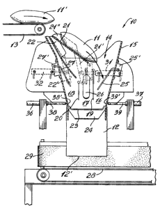
Referring now to the drawings and more particularly
to Fig. 1, there is shown generally at ,10 the automatic
article bagging machine of the present invention for placing
at least two, herein three, articles 11 in an outer bag 12.
As hereinshown the articles 11 are spaced apart on a feed
conveyor 13 and fed in an uninterrupted manner into the top
end 14 of the article receiving housing 15. In this
particular embodiment, the housing is provided with three
compartments and namely a first compartment 16 at one end of
CA 02160497 1999-07-15
-5-
the housing 15, a central compartment 17 and a third
compartment 18 at the opposed end of the housing. The
compartments are separated by partition wall sections 19 and
20.
s As also shown in Fig. l, there is provided two hinge
gates namely gates 21 and 22 which are supported respectively
on hinge arms 21' and 22', to displace the gates from a
loading position to an unobstructing position, as will be
described later. As also illustrated in this figure, the
~o housing is provided with an open bottom end 23 and against
which is secured a pivoting discharge gate 24 to release
articles from within the three compartments into the outer bag
12 supported adjacent the open bottom end 23. Each
compartment 16, 17 and 18 is also provided with a switch arm
15 25, 26 and 27 respectively and projecting therein in the path
of the articles discharged therein, to detect the articles 11
entering their respective compartments. The switch arms are
connected to an electric switch 25', 26' and 27' respectively
to send a signal to the control unit 30, as illustrated in
zo Fig. 2, whereby to advise the control unit that a pouch 11 has
been placed within a certain compartment. A discharge
conveyor assembly comprising a horizontal support conveyor 28
and a side guide conveyor 29 are located spaced closely below
the bottom end 12' of the outer bag 12 whereby to convey a
2s loaded bag away from the housing 15.
The control unit 30 is a programmable logic
controller which allows the programming of the sequence and
the length of time that the discharge gate 24 remains open.
It is also pointed out that the electric switches 25 to 27
3o could be replaced by photoelectric cells or proximity
switches.
Referring now additionally to Figs. 2 to 5 there
will be described the manner in which three succeeding pouches
11, 11' and 11" are loaded within the housing 15. As shown in
35 Fig. 1, as the first pouch 11 enters the first compartment 16
CA 02160497 1999-07-15
- Sa -
it will cause the switch arm 25 to pivot therefore causing a
switch closure of its associated electric switch 25' sending a
signal to the control unit that the first pouch is entering
the first compartment 16. The control unit is provided with a
s computer having a processor circuit and upon receipt of this
signal, or after a short predetermined time delay, will cause
the cylinder 31 connected to the hinge arm 21' of the hinge
gate 21 to pull the gate 21 to its unobstructing position, as
_216Q49'~
- 6 -
shown in Fig. 3. A second compartment 17 is now unobstructed
and the second pouch 11' has just been released onto the
second hinge gate 22 which guides the second pouch into the
central compartment 17. These gates 21 and 22 are provided
with opposed side walls 21" and 22" to assure that the pouch
is properly guided within the compartments. As the second
pouch 11' enters the central compartment, it will actuate its
associated switch arm 26 causing the electric switch 26' to
close sending another signal to the control unit to cause the
cylinder 32 associated with the second hinge arm 22' to
displace the hinge gate 22 to its unobstructing position as
shown in Fig. 4. The third pouch 11" is immediately released
within the third end compartment 18 and upon which closing the
switch arm 27 actuates the electric switch 27' and sends a
further signal to the control unit 30.
Upon receiving this third signal by the closure of
switch 27', the control unit immediately actuates the pivotal
discharge gate 24 which causes the open end of the bag 12 to
be grasped, as will be described later. The three pouches 11,
11' and 11" are discharged within the outer bag 12 having its
open end completely retracted,- as shown in Fig. 5. At that
moment, a fourth pouch 34 is being discharged within the third
compartment 18. The control unit is provided with a delay
circuit 35, as shown in Fig. 2, which has sensed the closure
of switch 27' identifying that this was the last loaded
compartment. The delay circuit, after a predetermined time
delay, sends a signal to one of the cylinders 36 or 37
associated with an article support means, herein a finger
element 38 and 39 respectively whereby to cause the finger
support element to enter its respective compartment 18 or 16,
through a port 38' and 39', respectively, and disposed above
the bottom open end 23 of -the compartments. This finger
support element 39 obstructs the open end whereby to hold the
next pouch being loaded in its associated compartment while
the gate is open, as clearly illustrated in Fig. 8.
As shown in Figs. 8 and 9, the fourth pouch 34 is
thus placed in the third compartment 18 and supported by the
CA 02160497 1999-07-15
finger support element 38 while the discharge gate 24 is still
open. Immediately after its discharge the gate 24 is pulled
back and releases the outer bag 12, as will be described later
which bag is transported away on the horizontal discharge
conveyor 28. Upon entry of the fourth pouch 34 within the
third compartment, the switch arm 27 has again been actuated
to send a signal to the control unit 30 advising it that it is
now time to actuate the second hinge gate 22 from its initial
unobstructing position to a guiding position as shown in Fig.
~0 9. The fifth pouch 40 has now arrived and is ready to be
discharged in the central compartment to its position as shown
in Fig. 9 and with the pivotal discharge gate 24 having been
completely retracted or being in the process of being
retracted. The switch arm 26 is actuated by the fifth pouch
40 and sends a further signal to the control unit which
displaces the hinge gate 21 to its initial position, as shown
in Fig. 1, whereby to receive into the ffirst compartment 16 a
sixth pouch (not shown). A reverse cycle has now been
completed and the machine now reverses its cycle again and
zo reloads the compartments. Accordingly, it can be seen that
the compartments are loaded sequentially and in an
uninterrupted alternating manner whereby a constant feed of
articles 11 is supplied from the feed conveyor 13 without
interruption.
zs Referring now to Figs. 6, 7 and 8 there will be
described the manner in which the pouches are loaded within
the outer bag 12. As shown in Fig. 6, a plurality of
juxtaposed bags 12 are retained on wicker pins 49 in a manner
well known in the art by positioning a pair of holes (not
so shown) provided in the flaps 48 of the bags 12 onto the wicker
pins 49. The bags are loaded with the outer wall 12' of each
bag facing towards the bottom end 23 of the housing 15. A
pair of air jet nozzles 50 are positioned in close proximity
to the open end of the outermost one of the bags and provide a
35 constant air stream in this area to cause the outer wall to
separate from its rear wall 12" as shown in Fig. 6. This
causes the mouth of a bag to open under the discharge gate 24.
_216Q~9'~
_$_
As shown in Fig. 6, the discharge gate is an L-
shaped gate having a pivotal link arm 51 secured to a pivotal
mechanism 52 actuated by a piston 53. When the piston 53 is
actuated by the control unit to open the gate 24, the gate
enters the open mouth 54 of the foremost bag 12 and retracts
the upper portion of the outer wall 12' against a bumper
element 55 disposed thereunder whereby to clamp the upper end
of the bag outer wall 12' between the discharge gate and the
bumper. At the same.time, the three pouches loaded in the
housing are discharged within the outer bag. The weight of
these pouches causes the flap 48 of the outermost bag to tear
from the wicker pins 49 releasing the rear wall 12" of the
bag. The bag is clamped before the pouches reach the bottom
of the bag. In order to prevent the bag 12 from tearing upon
release of the load of the three pouches therein, the bumper
element 55 is secured on a shock absorbing mechanism 56
comprising a pair of springs 57, only one being shown in Fig.
7, permitting the clamped front wall 12' to move downwardly
under the pulling force of the bag. Once the outer bag is
loaded, the discharge gate 24 is retracted by the piston 53 to
its initial position, as shown in Fig. 6, releasing the bag 12
onto the horizontal discharge conveyor 28, as shown in Fig. 8,
wherein the outer bag and its three pouches is immediately
conveyed away from the bagging machine 10.
Although, as above described, the finger support
elements 38 and 39 were described as operating individually,
they could also operate at the same time (see Fig. 8) for the
reason that the opposed end compartment, to the one being
loaded with a pouch after release of the discharge gate, does
not contain any pouch therein. Accordingly, that finger
support element would not hinder the operation of the machine.
Referring now to Fig. 10, there is shown adjustment
means in the form of threaded bolts 60, 61 and 62 secured to
the hinge arms 21' and 22' of the hinge gates 21 and 22
respectively, whereby to adjust the position of these gates.
The threaded bolts are provided with abutment heads 60', 61'
and 62' to abut against a shock absorbing stopper element 63,
CA 02160497 1999-07-15
-9-
64 and 65 respectively. These sound absorbing elements are
formed of rubber whereby to prevent metal contact and
eliminate unnecessary noise and wear due to the actuation of
the hinge gates. By threading or unthreading the bolts 60, 61
s and 62 it can be seen that the positions of the gates are made
adjustable. It can be appreciated that sequential operation
of the gates results in reduced wear and tear and longer
machine life.
It is within the ambit of the present invention to
~o cover any obvious modifications of the preferred embodiment
described herein, provided such modifications fall within the
scope of the appended claims.