Note: Descriptions are shown in the official language in which they were submitted.
2160~12
TEMFileNo. 106.1
~Cm.E: DISPLAY DEVICE
s
FTF.T T~ I)F T~TF INvFNTTON
The present invention relates to devices for displaying visual inf~rin~ n, such as
a-lv~- L;~ , notices or other signage, on tubular or elongate members.
l~A~KC'rR()l~ OF TTIF INVFNTTON
~ Isual inforrn~if.n is conventionally displayed on generally flat surfaces, be it a
large outdoor billboard, a poster hung from a ceiling in a grocery store, or a logo mounted
on an office wall.
In contrast, elongate tubular surfaces, such as bars or tubing used for handrails in
buses and subway cars, are usually dismissed as being unsuitable for carrying display
material for many possible reasons, for example the available display area is too small for
any meanirlgful display; it is difficult to mount and remove the display material from such
bars, especially if adhesives are used; the display material is susceptible to being damaged
20 (by vandals or the weather) if not shielded properly; and, the display material may pose a
danger to a user which grasps the bar, such as from paper cuts if the material's edges
delaminate from the bar.
Many highly desirable display or advertising locations are therefore overlooked.One such location is the chair-lift at ski resorts. A skier is usually seated in a chair-lift for
25 several minutes as it ascends the mountain. For safety reason3, resorts require that a
safety bar (which is typically pivotally hinged at both ends to the chair-lift's frame) be
lowered to protect the chair-lift's occupants from falling forward out of the lift. While
waiting to reach the end of the lift line, the skier has little to do but to stare over the safety
bar at the ~;UIlUUlldill~:~. The safety bar is therefore a prime location for a resort to display
30 1 l ullloliull~l material, safety messages, and the like.
Sûlutions to some ûf the problems noted above have been proposed in the prior
art, such as in U.S. patent 5,430,974 (Hering) and U.S. patent 2,918,741 (Welter), but
- 1 -
~ 2~6~2
they are adapted to very specific uses. The tubular sleeve in Hering can be used to cover
the free end of an amm on a tumstile, but is not suited for bars lacking such a free end; and
Welter discloses a grocery cart handle cover specifically suited for mounting over two
small diameter wires. Neither Hering nor Welter are suitable for use on the safety bar of a
5 ski lift, for example.
What is desrred therefore is a display device which overcomes the limitations ofthese other prior devices. Preferably the device should be mountable at any desired
location on an elongate member such as a bar or tube, and should provide a greater
display area than the member on which it is being mounted. Further, the device should
have a core to carry the display material and to elevate it away from the elongate member,
and a shell to shield the core and display material and to secure the core and display
material to the elongate member. Both the core and shell should be capable of being
mounted and dismounted quickly for easy I c~ ,clll~lL of display material.
15 SUl~fARY ( )F T~ ~NVFI~TT()N
In one aspect the invention provides:
A display device comprising:
(a) a core portion, mountable on an elongate member, for carrying display
material; and,
(b) a shell portion, receivable about said core portion, for shielding said display
material and for securing said core portion and display material onto said elongate
member.
In another aspect the invention provides:
A display device for a safety bar of a ski chair-lift comprising:
(a) a core portion having an elongate tubular body with a radially inner surfacefor engaging the safety bar and a radially outer surface for carrying display
material, wherein said outer surface provides a greater display surface for saiddisplay material than does said safety bar;
(b) a shell portion having a hollow tubular body with an outside surface and an
inside surface for securing the core portion and display material on the safety bar;
(c) sealing means for impeding moisture migration from the ambient to the
display material; and
~ 21~0612
(d) locking means for resisting rotation of the shell poriion about the safety
bar.
In yet another aspect the invention provides:
A method of displaying display material on an elongate member comprising:
(a) inserting a core portion for carrying the display material about said
elongate member;
(b) inserting a shell portion over said core portion; and
(c) securing said shell portion onto said elongate member.
10 ~F.~(~RTPTTnN OF T~F. nR ~WlN('TC
Fmho~im~antc of the invention will now be described, by way of example only, with
reference to the au~ ;.lg drawings, wherein:
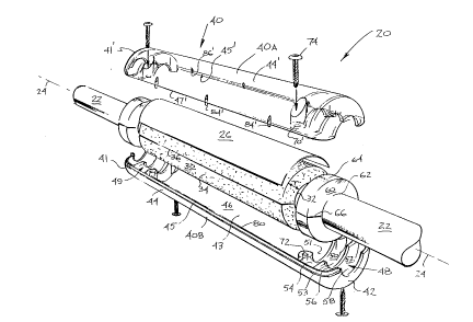
Figure I is a perspective view of a display device on an elongate member showingone embodiment of the present invention;
Figure 2 is an exploded view of the display device in Fig. I showing top and
bottom sectiorls of a shell portion detached from the elongate member;
Figure 3 is a plan view of the bottom shell portion shown in Fig. 2:
Figure 4 is an elevated side view of the bottom shell portion of Fig. 3;
Figure S is a plan view of the top shell portion shown in Fig. 2;
Flgure 6 is a cross-sectional view taken on the line 6-6 of Fig. 3; and
Figures 7, 8 and 9 show alternate ClllbOl~ of attachment means of the
invention;
nF..~13RTT'TTtlN ()F pRFTiFRRT~n F.Ml~O~TMF.NTS
Reference is ~rst made to Figures 1 to 6 (but primarily to Figs. I and 2) which
show a preferred embodiment of a display device 20.
In Fig. 1 the display device 20 is shown mounted on a tubular elongate member 22having a If)ngiT~ axis 24. The member 22 may be any cylindrical surface on whichone wishes to mount a display such as an au~Li~c.ll.,.-L, decal, notice, message or amy
30 other visual inforn~a~it\n As will become apparent later, the member 22 may be one which
has no free ends or is obstructed at both ends, namely obstacles on the member 22 prevent
another hollow tubular item of slightly larger inside diameter from being merely slid on or
2~0~2
offan end of the member 22. An example of such obstructed members are the safety bars
of ski chair-lifts which are usually hinged at opposite ends to the main frarne of chair-lif~s.
Hence, the ;Illr~ r portion ofthe safety bar illlul~lidL~I~ in front of a seated skier is
obstructed at both ends by these hinges. Other examples of a member 22 obstructed at
5 both ends are the horizontal elongate handles of fire escape doors commonly ell-,UUll~ d
irl most high-rise buildirlgs, and the vertical floor-to-ceiling handrails in buses and subway
cars. The member 22 may also be one which is only obstructed at one end and is
Ull~ b~LIu.,lcd at the opposite end, such as a fence post. The member 22 may also be non-
circular in cross-section, such as a square or rectangular shaped tube. For illustrative
10 purposes and ease of reference, the member æ will be referred to as a bar or safety bar
22, such as one found on a ski chair-lift.
The display device 20 has a core portion 30 for carrying display material 26, and a
shell portion 40 which is receivable about the core portion 30 and the display material 26.
As illustrated in Fig. 2, the core 30 has an elongate tubular body with a radially irlner
15 surface 32 for engaging the bar 22, and a radially outer surface 34 for carfying the display
material 26. The irlner arld outer surfaces 32, 34 are spaced. a radial distance T, which
denotes the "thickness" of the core's body. In this ~ lf~ the thickness T is uniform
about the ~ ,u~l~f~,l cl,~,e of the core 30, but it will be appreciated that the thickness T may
be irregular in alternate ~ od;~ Lb.
20 Ideally the irmer surface 32 of the core 30 is shaped and fl; " .~ ;. ,"r rl to fit snugly
onto the bar 22. However, since the diameter of the bar 22 may vary (for example, the
safety bars on different chair-lifts are not necessarily the same), the diameter of the inner
surface 32 is preferably made large enough to ft more than one size of bar, and so the
core 30 might fit rather loosely on a smaller diarneter bar. The fit should not be so loose as
25 to adversely impact the pclrul~ of the display device 20.
The core 30 is preferably made of a flexible and ,u~ lc~ble material, such as
foam rubber, so that the core 30 is mountable on the bar 22 via a single lf)n~ rlin~l cut or
sht 36 through the core body. The core 30 may therefore be mounted directly onto the
bar æ at a desired display location, regardless whether the bar 22 is ob$ructed at one or
30 both ends. Although there may be more than one slit provided, thereby splitting the core
bo~ ' bto~everdpalts,a~ i5p~--~edsothat~;ody3~isoneintet al
211~0612
and so that the e;a5ticity of the body 30 causes it to c u~ y close about the bar 22
upon mounting.
The display material 26 is preferably carried on a sheet which is insertable onto the
outer surface 34 for easy removal and ~cpla~c~l~c~ with sheets having other displays. If
5 desired, some adhesive may be placed between the sheet 26 and the core to help retain the
sheet on the outer surface 34 when mounting the display on the bar 22. It will be
appreciated that the display material may also be integral with the outer surface 34. For
inst~mce, the material may be laminated or printed directly onto the core 30. A change of
display material would therefore require l~ldCc~ of the core 30 or the insertion of
10 another sheet of display material over the existing core.
The shell portion 40 shields the display material 26 and the core 30 from hazardous
conditions, be they weather related or vandalism, and secures them onto the bar 22. The
shell 40 has a hollow tubular body with tapered end walls 41 and 42, a rounded inside
surface 43, and a ~,oll~olld...~ rounded outside surface 44 exposed to the ambient. It is
15 noted that the shell's entire outside surface 44 is smooth and rounded, and is free of sharp
edges or ~lvLlubdl~ which might harm or injure someone. Where required, the shell 40,
and in particular tne end walls 41, 42, may have small apertures (not shown) for venting
moisture from within the display device to the ambient.
The shell 40 is divided Inn~if~ y into top and bottom sections 40a and 40b (as
20 viewed in Fig.2) for mounting onto the bar 22 regardless whether the bar is obstructed at
one or both ends. In this embodiment the sections 40a and 40b are reversed rnirror images
of themselves - i.e. both sections are identical, except that bottom section 40b is rotated
180 degrees about the l~ ".l:. ' axis 24 relative to top section 40a (for example,
...' edge 45 of bottom section 40b ~ ~olld~ to lfmejfll(lin~l edge 451 of top
25 section 40a furthest from the viewer in Fig.2). Although it will be appreciated that both
sections of the shell 40 need not be identical, having identical halves provides", ",r~..""..,~ and assembly efficiencies, ~SOllv~,lh~ S and cost savings. For ease of
reference, only bottom section 40b is described in detail. Primed numerals are used to
identify like elements on top section 40a in Figures 1, 2 and S.
The hollow body of the shell 40 is divided into a central cavity 46 for housing the
core 30, and first and second side cavities 48 and 49 on either side of the central cavity 46.
Since the core 30 is .l;..,~,lc,.."..l to elevate or push the display material 26 against the
- 5 -
~ 21fiO612
shell 40, the core and display materiai frictionaily engage the inside surface 43 of the
centrai cavity 46 which deters the core and display material 26 from moving relative to the
sheii 40. The outer surface 34 of the core 30 and the inside surface 43 of the sheii should
be sized to siightly compress the display material 26 when the top and bottom sections
5 40a, 40b of the shell are secured together, but not so much that the display material 26 is
damaged or distorted. It will be understood that the sizing of the core's thickness T
relative to the radiai opening formed by the centrai cavity 46 will depend on several
factors, including the ~ ,JalbiliLy ofthe core's material amd the thickness ofthe display
sheet 26 (assuming a separate sheet is used, as mentioned earlier). For instance, there may
10 be iittle contact between the core material and the shell if the display 26 is made of a very
thick cardboard or foam and the core material is relatively stiff In the preferred
llclllll.. .11, the core's foam rubber is relatively cu~ alble and the display is on a thin
sheet 26. Hence, it is desirabie that the outer surface 34 of the core have a slightly larger
diameter than the inside surface 43 of the centrai cavity 46 to achieve the above noted
15 U~ l,Vltaa;~ andfrictionairl~
In the preferred r~ udilllt;u~, the side cavities 48 and 49 are mirror images of each
other. Since both cavities have like features, then for brevity and clarity oniy the features
of the first side cavity 48 need be described in detail. The side cavity 48 is separated from
the centrai cavity 46 by a partition 50 having a slot 51 for receiving the bar 22. A wail 52
20 further divides the side cavity 48 into inner chamber 54 and outer chamber 56. The
dividing wail 52 aiso has a slot 53 for receiving the bar 22. Likewise, the end wall 42 of
the bottom sheil section 40b has a slot 58 for receiving the bar 22. The slots 51, 53 and
58, and their uuu~ Jal La in the second side cavity 49 and the top section 40a, permit the
sheli sections to be joined together and mounted on the bar 22 These slots should fit as
25 tightly as possible around the bar 22 for maximum illL~Irtl~ with any moisture or dirt
migration aiong the bar 22 from the ambient to the centrai cavity 46.
The inner charnber 54 adjacent the centrai cavity 48 is configured to receive and
house an o-ring 60. The o-ring is an annuiar body of elastomeric material with a radiaily
irmer surface 62 for frictionaily engaging the bar 22, and a radiaiiy outer surface 64 for
30 frictionaiiy engaging the inside surface 43 of the shell chamber 54. A slit 66 through the
body is provided for inserting the o-ring 60 onto the bar 22, like the slit 36 on the core 30.
The o-ring 60 is .l;"~ ..lfd for a tight fit within the chamber 54, namely, the diameter of
- 6 -
21~12
the o-ring's outer surface 62 is preferably the same as or marginally larger than the
diameter of the inner chamber's inside surface 43 to provide a frictional fit between the
shell 40 and the o-ring 60. Likewise, the o-ring 60 should fit snugly on the bar 22 to
optimize fiictional rl~ gr~ between the o-ring and bar. The fit should not be so tight
S as to prevent both shell sections from properly mating about the bar 22, yet should be tight
enough so that the chamber 54 squeezes the o-ring to maximize the above noted frictional
The o-rings on each side of the core 3 0 effectively lock or clamp the shell
40 in a desired orientation and resist further movement of the display device 20 on the bar,
be it twisting about the bar or sliding along the bar. Suitable results have been obtained
10 using an elastomeric material such as urethane rubber with a specified durometer value of
60, with the actual durometer value falling m the range between 50 and 70 The rubber
may be custom extruded or die cut from sheet material for a uniform fit about the inner
chamber 54 to avoid differential squeezing about the ~ ul-lrel ~I-ce of the o-ring.
It will be appreciated that the o-rmg 60 also impedes moisture and dirt from
15 migrating firom the ambient to the central cavity 46 through the side cavity 48. To further
impede moisture or dirt which may find its way into the central cavity from reaching the
display material 26, the core material preferably has water-repellent qualities. Water
repellency is particularly important in cold rllvilO~ r,llL~, such as in ski areas, since water's
expansion upon fireezing can crack and severely damage a structure
The top and bottom sections 40a and 40b of the shell are attached together on the
bar 30 using an attachment hl 1 ~ showrl in Fig. 2. A recessed aperture 701 in the
top section 40a is aligmed with another hole 72 in the bottom section 40b, and a self
threading fastener or screw 74 is passed through the aperture 701 and is threaded into the
hole 72 to clamp and secure both sections together on the bar 22. The aperture 701
25 provides free passage for the screw 74, whereas the hole 72 is of a smaller diameter than
the screw 74 to provide the noted threading and clamping action. Four sets of this
aperture/hole/screw all~l~,.,,...,.l~ are located on the shell 40 as shown. Suitable results
have been achieved by locating the holes and apertures adjacent the partitions 70. This
location not only places the screws 74 by the o-rings 60, where the greatest clamping
30 forces are required, but the structure of the partitions helps distribute the clamping force
about the shell. It will be appreciated that by recessing the aperture 701, the screw's head
- 7 -
0612
is kept from protruding above the shell's smooth outside surface 44. Possible alternate
attachment all~lgCll~ i are shown in Figures 7, 8 and 9, although they are not preferred.
The shell 40 also has guides to help a user properly mate both top and bottom
sections 40a, 40b together. Referring to Figures 2, 3 and 6, the periphery of the shell
S section 40b has a tongue 80 on lnneiflltiinql edge 45 and a CU-lC~ Jlld;ll~ groove 82 on
the opposite Inn~ifll~linql edge 47 (which is obstructed from view in Fig. 2). The tongue
and groove extend along the entire periphery bounding the central cavity 46 and the inner
chamber 54, and a part of the outer chamber 56 When the shell sections are properly
mated, the tongue and groove overlap one another. In this embodiment, the tongue and
10 groove ~ ,rlrl...l also performs a sealing function by impeding water and dirt from
migrating across the shell's periphery and into the central cavity 46. Hence, although the
tongue and groove need not be continuous as shown for mating purposes and may have
gaps along their lengths, this is not preferred for sealing purposes
Also provided at selected locations along the periphery of the shell are projections
15 84 and c<~ *,olldillg ledges 86. The projections 84 of one shell section approach the
ledges of the other shell section to help hold the periphery in place during assembly of the
shell. The projections and ledges serve other functions as well: the projections 84 help
prevent the core body 30 from extending onto the lnnei~l-iinq~ edges 45, 47 and being
pinched by the periphery during assembly; and, as shown in Fig. 6 the bases of the
20 projections and ledges (i.e. the lowermost junctions of the projections and ledges with the
inside surface 43 of the shell) define a boundary or perimeter in which to fit the display
sheet 26.
In the preferred c...bo 1;1I1.,I.L, the entire shell is made of a transparent material so
as not to obstruct the view of any part of the display 26. Good results have been achieved
25 using durable and shatter-resistant plastics, such as LEXAN`rM If desired, the shell
material may be colour tinted, or it may be opaque over non-display locations, such as the
side cavities 48, 49.
It may now be appreciated that a desirable feature of the device 20 is the addeddisplay surface area provided by the core 30, as opposed to the surface area available on
30 the face of the bar 22. The display area on the outer surface 34 will vary depending on the
thickness T of the core 30 (and more specifically the outer surface's diameter) and the size
of the shell portion 40. In the preferred C~lbOd;~ , the thickness T is about the same as
-- 8 -
21~fil2
the radius of the bar 22, thus the ~,u~ lre~ of the outer surface 34 is ~ Lely
double that of the bar 22, providing twice the display space of the bar 22. Hence, where
previously it may not have been feasible to display ads or notices on the bar 22 (because of
its small diameter, the difficulty of retaining the material on the bar, etc.), the present
5 mvention now provides a viable means of doing so
It may now also be appreciated how display material may be mounted onto the bar
22 using the preferred eulbodu~ of the present invention. First the core 30 is inserted
onto the bar 22 at a desired display location. O-rings 60 are inserted onto the bar 22 on
each side of the core 30. E the display material is on a sheet 26, then the sheet is placed
10 onto the core m a desired orientation for viewing; and rf the display is integral with the
core, the core should be rotated to the desired orientation. Alternately, the display sheet
26 may be inserted mto place into one or both shell portions as illustrated in Fig. 6. The
shell portions 40a and 40b are then inserted over the core 30 and the o-rings 60, and are
clamped together and to the bar usmg the four screws 74. The reverse procedure is used
15 to change the display material, except that the core and o-rings need not be removed from
the bar.
The above description is intended in an illustrative rather than a restrictive sense
and variations to the specific ~ and materials described may be apparent to
skilled persons m adapting the preseffl invention to specific d~)~' Such variations
20 are intended to form part of the present invention insofar as they are within the spirit and
scope of the claims below. For instance, satisfactory results may also be achieved by
hinging the shell halves along one edge rather than having two separate halves. Another
variation may be the inclusion of lugs on the inside surface 43 of the shell to achieve a
mechanical interlock (m addition to or instead of the frictional rl~ ) between the
25 shell and both the core and the o-ring. Yet another variation may be the le~ld~ lL of
the o-ring 60 with a urethane rubber or other suitable compound along the bar engaging
surfaces of one or more of the slots 51, 53 and 58 to achieve the locking and sealing
effects discussed earlier. Another variation may also be the printing of the display material
directly on the shell portion and omitting the core portion, but this is not desirable because
30 lq~ of the display material would require . epld~elll~,.ll of the shell. Also, omission
of the core would remove any support the core may provide to the shell above the central
cavity.
g