Note: Descriptions are shown in the official language in which they were submitted.
2~.61~~~.
-1-
Description:
Excess speed detector with multiple light barrier
The invention concerns an excess speed detector with multiple
light barrier and a flag track for the production of a shaft
information for a 1 ift pl ant.
In lift plants, buffers are installed in the shaft pit as safety
equipments. In case of faulty functions of the drive, the cage on
travelling past the lowermost stop or the counterweight or travelling
past the uppermost stop is braked in defined manner. In the case of
lifts with high nominal speeds, very large buffers are needed for
this, which makes a deep shaft pit necessary and is correspondingly
expensive to build. The lift regulations permit only shortened
buffers insofar as the retardation of the 1 ift cage is monitored by
an independent safety equipment. This retardation check must in the
case of a fault make certain that the maximum permissible buffer
impact speed, which in the case of shortened buffers is smaller than
the nominal speed, is not exceeded.
Such an equipment for the speed monitoring and stop initiation,
in particular for lift cages, has become known by the US-PS 4 499
974. In this equipment, a flag track is mounted at one side of the
lift shaft. A detector, for example in the form of a forked light
barrier, is fastened at the cage. When the cage travels through the
shaft and the 1 fight beams of the 1 fight barrier are interrupted, the
time of the interruption is measured. When the time of the
interruption is smaller than a preset value, this is then a measure
for excess speed. The individual flags of the flag track are each so
dimensioned that the preset passage times are fallen below and the
safety switching elements are triggered when they are passed at more
than the maximum permissible speed.
In the case of the of oredescribed equipment, the speed of the
cage is ascertained with the aid of a single measuring or checking
equipment. It can not be recognised whether the light barrier
engages sufficiently deeply into the flags in order to assure an
interruption of the light beams. The absence of the flag track or
even only individual flags can likewise not be ascertained
CA 02161291 2004-09-27
_2_
immediately thereby. Moreover, it can not be recognised with this
equipment without interrupting the current circuit whether the working
contacts of the safety switching elements function in order to make certain
that they can actually be opened in the case of a fault.
The invention is based on the object of proposing an equipment for the
ascertaining of excess speed of the initially named kind, which does not
display its disadvantages and assures a high safety.
The advantages achieved by the invention are to be seen substantially
in that all the aforementioned fault functions can be recognised and the
safety switching elements can be triggered by reason of an additional check
track mounted at the flag track and a redundant forked light barrier.
Advantageous developments and improvements of the excess speed
detector are possible through additional measures provided by the invention
and, due to redundancy of the safety switching elements and a check
circuit, faults of the relays can be recognised without interruption of the
working current circuit.
In one aspect, the present invention provides an apparatus for
detecting excess speed of an elevator car travelling in an elevator shaft
comprising: a speed measuring strip having an elongated body adapted to
be mounted vertically extending in an elevator shaft, said strip having a
vertically extending markings track side-by-side with a vertically extending
check track, said markings track having a plurality of vertically spaced apart
speed markings thereon and said check track having a plurality of check
markings thereon in predetermined positions relative to said speed markings;
a forked light barrier assembly adapted to be mounted on an elevator car
movable in the elevator shaft, said assembly including a pair of legs
extending on opposite sides of said speed measuring strip and a plurality of
light barriers for transmitting beams of light between said legs; and an
excess speed detection circuit connected to said light barriers and being
responsive to a detection of said speed markings for generating a open relay
signal to stop the car, said excess speed detection circuit being responsive
to said speed markings and said check markings for generating said open
CA 02161291 2004-09-27
-2a-
relay signal when said speed markings and said check markings are not
detected in a predetermined order.
In another aspect, the present invention provides an apparatus for
detecting excess speed of an elevator car travelling in an elevator shaft
comprising: a speed measuring strip having an elongated body adapted to
be mounted vertically extending in an elevator shaft, said strip having a
vertically extending markings track side-by-side with a vertically extending
check track, said markings track having a plurality of vertically spaced apart
speed markings thereon and said check track having a plurality of check
markings thereon in predetermined positions relative to said speed markings;
a forked light barrier assembly adapted to be mounted on an elevator car
movable in the elevator shaft, said assembly including a pair of legs
extending on opposite sides of said speed measuring strip and a plurality of
light barriers for transmitting beams of light between said legs, each of said
light barriers being associated with one of two channels and corresponding
ones of said light barriers in each said channel performing similar functions
to provide redundant detection of said speed markings and said check
markings; and an excess speed detection circuit connected to said light
barriers and being responsive to a detection of said speed markings for
generating a open relay signal to stop the car, said excess speed detection
circuit being responsive to said speed markings and said check markings for
generating said open relay signal when said speed markings and said check
markings are not detected in a predetermined order.
In a further aspect, the present invention provides an elevator system
comprising: an elevator car movable in an elevator shaft; a speed measuring
strip having an elongated body mounted vertically extending in said elevator
shaft, said strip having a vertically extending markings track side-by-side
with a vertically extending check track, said markings track having a
plurality of vertically spaced apart speed markings thereon and said check
track having a plurality of check markings thereon in predetermined positions
relative to said speed markings; a forked light barrier assembly mounted on
said elevator car movable in said elevator shaft, said assembly including a
pair of legs extending on opposite sides of said speed measuring strip and a
CA 02161291 2004-09-27
-2b-
plurality of Light barriers for transmitting beams of light between said legs;
an excess speed detection circuit connected to said light barriers and being
responsive to a detection of said speed markings for generating a open relay
signal to stop the car, said excess speed detection circuit being responsive
to said speed markings and said check markings for generating said open
relay signal when said speed markings and said check markings are not
detected in a predetermined order; and a safety means connected between
said car and said excess speed detection circuit and being responsive to said
open relay signal for stopping movement of said elevator car in said shaft.
Three examples of embodiment of the invention are illustrated in the
drawing and explained more closely in the following. There show:
Fig. 1 a schematic illustration of a lift plant with a first example of
embodiment of the measuring strip according to the equipment
according to the invention,
Fig. 2 a forked light barrier according to the equipment according to
the invention,
Fig. 3 a functional block diagram according to the equipment
according to the invention,
Fig. 4 a signal course diagram of the forked light barrier in the
fault-free operational state without excess speed,
Fig. 5 a signal course diagram of the forked light barrier in a faulty
operational state,
Fig. 6 a second example of embodiment of the measuring strip
according to the equipment according to the invention,
_ 2161.2~~
-3-
Fig. 7 a third example of embodiment of the measuring strip
with a longitudinal section through the forked light
barrier according to the equipment according to the
invention and
Fig. 8 a signal course diagram of the forked light barrier
according to the third example of embodiment.
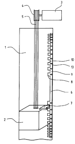
Fig. 1 shows a schematic illustration of a lift plant with an
equipment according to the invention for the detection of excess
speed. A cage 2, which is guided in a lift shaft 1, is driven by way
of cables 5 from a drive motor 3 with a drive pulley 4. The
measuring strip 6 is mounted on one side of the lift shaft 1. A
forked light barrier 7 is arranged at the cage 2, preferably on the
cage roof. The measuring strip 6 consists of a markings track in the
shape of a flag track 8 and a check track 9 and is made of a highly
resistant material, preferably of steel sheet. The forked light
barrier 7 is so arranged on the cage roof that it engages into the
flag track 8 and into the check track 9. The measuring strip 6 is
mounted over the entire shaft length. Markings in the form of flags
and windows 13 are arranged at the measuring strip 6 for scanning
by the forked light barrier 7. A window 13 is arranged in the check
track 9 at those places, where a flag 10 stands in the flag track 8.
At this place, the light beam of the forked light barrier 7 is tree
each time at the control track 9 and can be tested. By reason of
this arrangement, it is made certain that at least one light barrier
is always interrupted. The length of the flags 10 is matched each
time to the maximum speed of the cage 2, i.e. the flag segments 10
become ever shorter towards the upper and lower shaft end. When the
depth of engagement of the forked light barrier 7 into the flag track
9 is now not correct or a flag 10 is absent, all light barriers
become free.
By reason of this state, the faults are recognised and the
safety switching elements are opened by the control.
The structuring of the markings at the measuring strip 6 can
also take place in different other ways, such as for example as
slots, holes or in the shape of a strip with reflecting and non-
reflecting portions.
Fig. 2 shows a forked light barrier 7. This forked light
_ z~s~~~~
- 4 -
barrier 7 is built up in two channels each with three, preferably
infrared light barriers 14 for each channel and with a monitoring
circuit which compares the state and the measurement results of both
the channels. A first light barrier 15 and 16 is used for each
channel in order to measure the passage time of the flag 10. The
second light barrier 17 and 18 is displaced vertically in order that
it can be ascertained whether the flag was passed or only touched.
The third light barrier 19 and 20 is disposed in the check track 9
and serves for ascertaining whether all flag segments 10 are present
and the forked light barrier 7 is mounted correctly. Both channels
of the forked light barrier 7 take over the same functions. In order
to exclude a mutual influencing of the altogether six light barriers
14, only one transmitter is switched in each time. The co-ordination
between the light barriers 14 is taken over by a switching-over of
the channels. Should a fault arise in the channel switching, the
safety switching elements are opened. It is recognised as a faulty
function when both the channels transmit at the same time or when the
time requirement for the operation of a light barrier 14 deviates
from the normal value. Both the channels measure the flag passage
time each independently of the other.
Fig. 3 shows a functional block schematic diagram according to
the equipment according to the invention. The channel A and the
channel B are constructed identically. Only the channel A is
described in the following. A channel switching 24 takes over the
co-ordination of the light barriers 14, i.e. the switching-over from
one light barrier 14 to the next one of both the channels A and B.
Equally, the optical parts 25, 26 and 27 are built up identically.
They consist substantially of transmitter and receiver units as well
as a sequence control and transmitter and receiver test units. The
build-up of such a light barrier is described in the EP 483 560. The
first two optical parts 25 and 26 scan the flag track 8. The flank
recognitio n 28 starts a counter 29 on a flag 10 being entered. On
coming out of the flag 10, the counter 29 is stopped, the counter
state is passed over to an intermediate storage device 30 and the
counter 29 is again reset. Thereby, the counter 29 is again ready
for the next time measurement. It can happen that the counter 29 is
_. _21612~~
-5-
started at a' flag edge due to toggling, i.e. oscillating upward and
downward movements. In this case, the counter 29 is reset by a
toggle recognition 31 and the passage is recognised as incorrect.
When a correct flag passage has thereagainst taken place, the
evaluation of the counterstate is caused by the toggle recognition 31
to take over and check the count value. When the count value lies
below a defined limit value, then the flag 10 was travelled through
too fast, which is equivalent to excess speed. In the case of excess
speed, the safety relays 34 and 35 are opened and the lift thus
stopped. After a valid flag passage, the counter states (the
measurement values) are present at both channels A and B.
Differences between both the enter states are recognised by the
counter comparison with count tolerance consideration 36 and lead to
the opening of the safety relays 34 and 35.
The counter 29 counts a constant counting rate 37. The
monitoring of the time base 38 checks the counting rate 37. An
incorrect check track signal 39 is detected by the monitoring of the
check track 40. A relay watchdog 41 checks the reset pulses.
Optical error signals 42 can be detected by the receiver and
transmitter test units of the optical pulse 25, 26 and 27. Should
one of the aforementioned faults arise, the safety relays 34 and 35
are opened.
The relays 34 and 35 comprise two switching contacts 45 and 46,
which are constrainedly moved one to the other and of which each
switch contact is in one working current circuit 47. The second
relay contact serves for the monitoring of the relay states 48.
Faulty relay states lead to a relay switching-off command. In the
normal lift operation, no excess speed arises. This has the
consequence that the relays 34 and 35 need never be switched off and
their function can thus not be checked. In order to check the
function of the relay safety contacts, these must be opened without
interrupting the working current circuit. For that reason, two
safety relays (34, 35), the switching contacts (45, 46) of which are
connected in parallel, are installed for each channel (A, B). The
function of the working contacts can be checked by way of the
contacts constrainedly led to working contacts when the relay (34,
_. _ 2161~'~~
-6-
35) is switched. With the aid of the bridging-over of the working
current circuit 49, this test becomes possible without opening the
working current circuit 47.
Fig. 4 shows a signal course diagram of the forked light barrier
in the fault-free operational state without excess speed. The upper
course represents the flag track signal 51 and the lower course
represents the check track signal 52. During the movement of the
flags 10 through the light barrier 15, the passage time 53 is
measured and a possible excess speed detected. Since one flag 10 and
one window 13 always stand one opposite the other at the measuring
strip 6, the absence of flag segments 10 or a faulty positioning of
the forked light barrier 7 can be recognised at once, since a check
window recognition 54 always takes place within the passage time 53
of the flags 10.
Fig. 5 shows a signal course diagram of the forked light barrier
in the case of an incorrect depth of engagement of the forked light
barrier 7 or in the case of absent flag segments 10. In both cases,
the light beams become free simultaneously at the flag track 10 and
the check track 9. The check track monitoring 40 and the flank
recognition 28 recognise the fault state 55 and cause an opening of
the safety relays 34 and 35. As soon as a fault arises, the channel,
which has first discovered it, releases its relays and gives the
relay switching-off command to the other channel.
Fig. 6 shows a second example of embodiment of a measuring strip
65 according to the equipment according to the invention. This
measuring strip 65, apart from a markings track in the shape of a
flag track 66 and a check track 67, in addition still displays a
safety track 68. This track serves for the additional checking in
the upper and lower shaft end. For this purpose, the measuring strip
65 displays a free strip 69, which in the region of the upper and the
lower shaft ends displays at least one respective marking in the form
of a slot or a hole 70, between the flag track 66 and the check track
67. The forked light barrier belonging to this example of embodiment
therefore comprises a further light barrier pair which can detect the
end of the shaft with the aid of the slot or the hole 70. The
arrangement of the flags 10 and windows 13 is identical with the
-- _ ~~s~~~~
_7_
first example of embodiment. This construction enables an
additionally high operational reliability against faulty triggering,
such as for example in the case of possible contamination of the
measuring strip 65, when the check windows 13 can no longer be
recognised by the light barriers 19 and 20.
Fig. 7 shows a third example of embodiment of a measuring strip
75 with a longitudinal section through the forked light barrier 76
according to the equipment according to the invention. This
measuring strip 75 consists of a markings track in the form of a
window track 77 and a check track 78. The measuring strip 75
displays markings in alternation in the shape of windows 79 on the
window track 77 and the check track 78. The windows 79 of both
tracks have the same size and are each time arranged centrally
between two windows 79 of the other track. By reason of this
arrangement of the windows 79, the light barriers 80 of both the
channels A and B are arranged symmetrically. The measurement value
registration can take place through the freeing or through the
interruption of the light beams of the light barrier in the track
concerned. An advantage of this variant is that a contact safety
device, which prevents a tearing-off of the measuring strip 75 in
consequence of protruding parts, is formed by a web 81 in front of
the window track 77.
Fig. 8 shows a signal course diagram of the light barriers 80
according to the third 'example of embodiment. This signal course
diagram shows a fault-free operational state. The upper course
represents the window track signal 82 and the lower course represents
the check track signal 83. The detection of excess speed takes place
in the same manner as for the first example of embodiment. It can be
recognised as further faults when a pulse is absent or a channel has
constant level 0 or constant level 1.